- Главная
- Английский язык
- Cold Weather Operation-General
Содержание
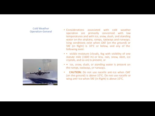
- 3. Cold Weather Operation-General Considerations associated with cold weather operation are primarily concerned with low temperatures and
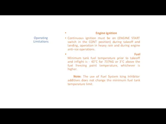
- 4. Operating Limitations Engine ignition Continuous ignition must be on (ENGINE START switch in the CONT position)
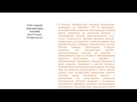
- 5. Учёт низкой температуры топлива (Fuel Freeze Temperature) В полете температура топлива постепенно снижается до значения ТАТ.
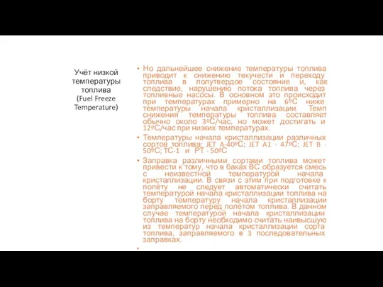
- 6. Учёт низкой температуры топлива (Fuel Freeze Temperature) Но дальнейшее снижение температуры топлива приводит к снижению текучести
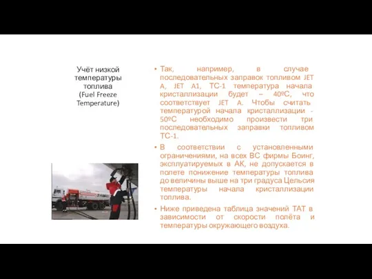
- 7. Учёт низкой температуры топлива (Fuel Freeze Temperature) Так, например, в случае последовательных заправок топливом JET A,
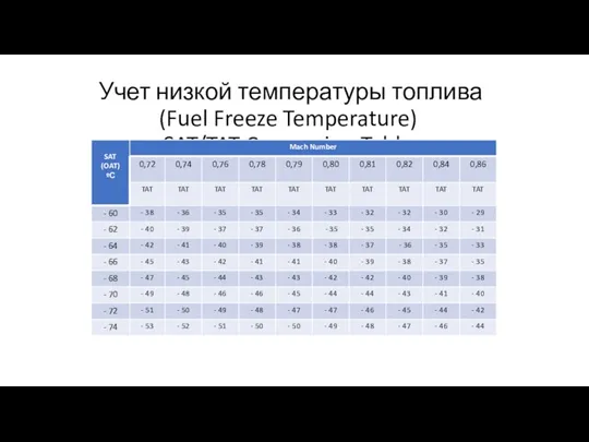
- 8. Учет низкой температуры топлива (Fuel Freeze Temperature) SAT/TAT Conversion Table
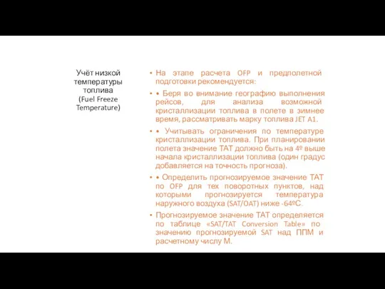
- 9. Учёт низкой температуры топлива (Fuel Freeze Temperature) На этапе расчета OFP и предполетной подготовки рекомендуется: •
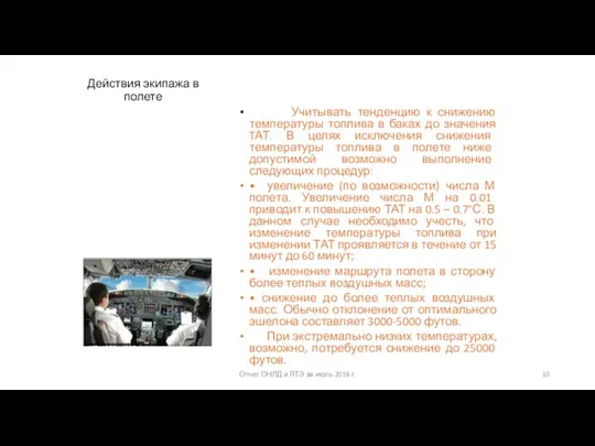
- 10. Действия экипажа в полете Учитывать тенденцию к снижению температуры топлива в баках до значения TАТ. В
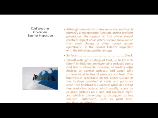
- 11. Cold Weather Operation Exterior Inspection Although removal of surface snow, ice, and frost is normally a
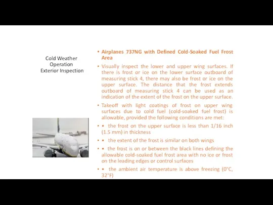
- 12. Cold Weather Operation Exterior Inspection Airplanes 737NG with Defined Cold-Soaked Fuel Frost Area Visually inspect the
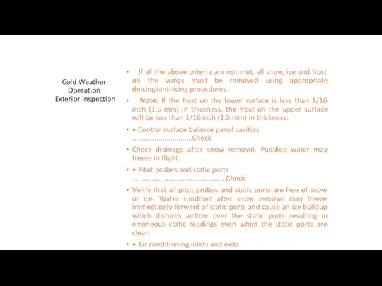
- 13. Cold Weather Operation Exterior Inspection If all the above criteria are not met, all snow, ice
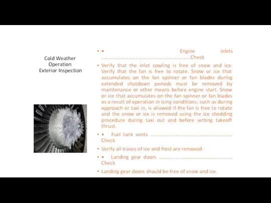
- 14. Cold Weather Operation Exterior Inspection • Engine inlets ...............................................................Check Verify that the inlet cowling is free
- 15. Температура в салонах К моменту посадки пассажиров температура воздуха в салоне должна быть не ниже +15°С
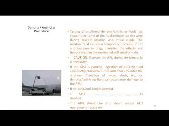
- 16. De-icing / Anti-icing Procedure Testing of undiluted de-icing/anti-icing fluids has shown that some of the fluid
- 17. De-icing / Anti-icing Procedure Call “FLAPS UP”. Flaps........................................................................UP Prevents ice and slush from accumulating in flap
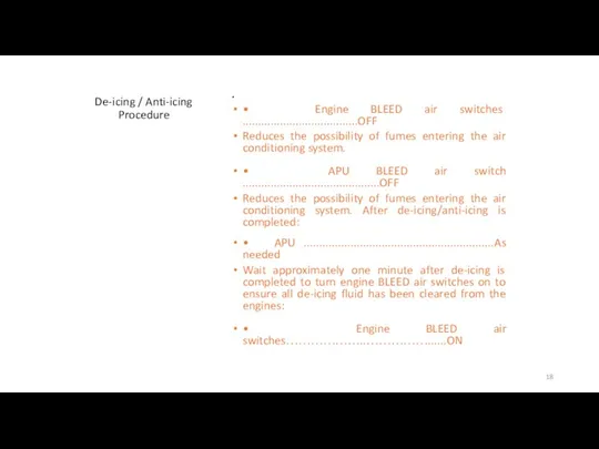
- 18. De-icing / Anti-icing Procedure • Engine BLEED air switches .....................................OFF Reduces the possibility of fumes entering
- 19. Engine Start Procedure Do the normal Engine Start Procedure with the following modifications: • If ambient
- 20. Engine Start Procedure • If the engine has been cold soaked for one or more hours
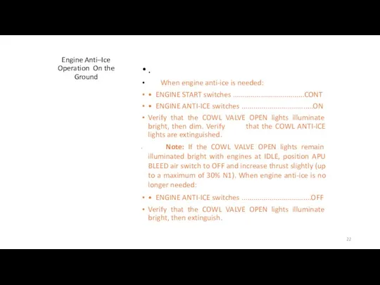
- 21. Engine Anti–Ice Operation On the Ground Engine anti-ice must be selected ON immediately after both engines
- 22. Engine Anti–Ice Operation On the Ground . When engine anti-ice is needed: • ENGINE START switches
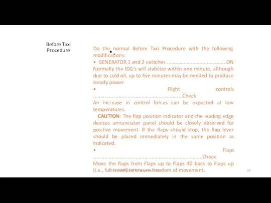
- 23. Before Taxi Procedure . Отчет ОНЛД и ЛТЭ за июль 2016 г. Do the normal Before
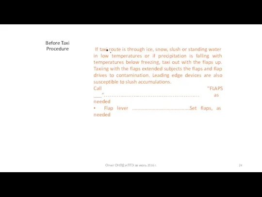
- 24. Before Taxi Procedure . Отчет ОНЛД и ЛТЭ за июль 2016 г. If taxi route is
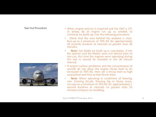
- 25. Taxi-Out Procedure When engine anti-ice is required and the OAT is 3°C or below, do an
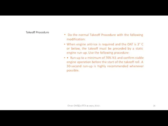
- 26. Takeoff Procedure Do the normal Takeoff Procedure with the following modification: When engine anti-ice is required
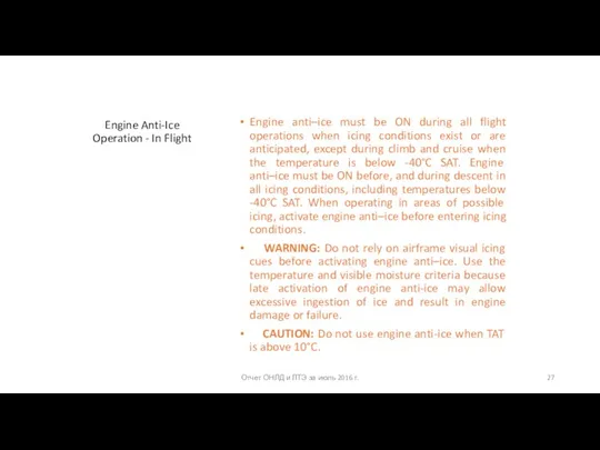
- 27. Engine Anti-Ice Operation - In Flight Engine anti–ice must be ON during all flight operations when
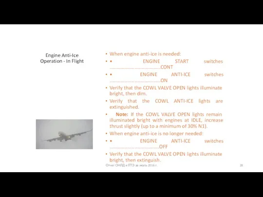
- 28. Engine Anti-Ice Operation - In Flight When engine anti-ice is needed: • ENGINE START switches .....................................CONT
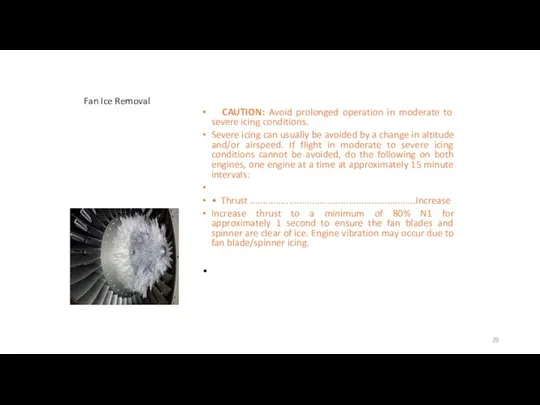
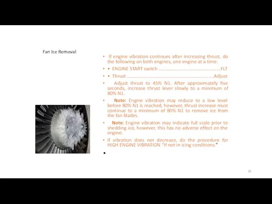
- 29. Fan Ice Removal CAUTION: Avoid prolonged operation in moderate to severe icing conditions. Severe icing can
- 30. Fan Ice Removal If engine vibration continues after increasing thrust, do the following on both engines,
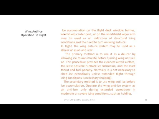
- 31. Wing Anti-Ice Operation In Flight Отчет ОНЛД и ЛТЭ за июль 2016 г. Ice accumulation on
- 32. Wing Anti-Ice Operation In Flight Отчет ОНЛД и ЛТЭ за июль 2016 г. CAUTION: Do not
- 33. Approach and Landing For 737 NG airplanes: Use normal procedures and reference speeds unless a flaps
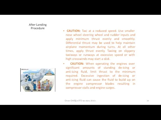
- 34. After Landing Procedure CAUTION: Taxi at a reduced speed. Use smaller nose wheel steering wheel and
- 35. After Landing Procedure Do the normal After Landing Procedure with the following modifications: After prolonged operation
- 36. After Landing Procedure CAUTION: Do not use engine anti-ice when OAT is above 10°C. When engine
- 37. After Landing Procedure When engine anti-ice is required and the OAT is 3°C or below, do
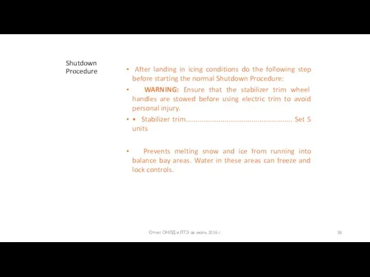
- 38. Shutdown Procedure After landing in icing conditions do the following step before starting the normal Shutdown
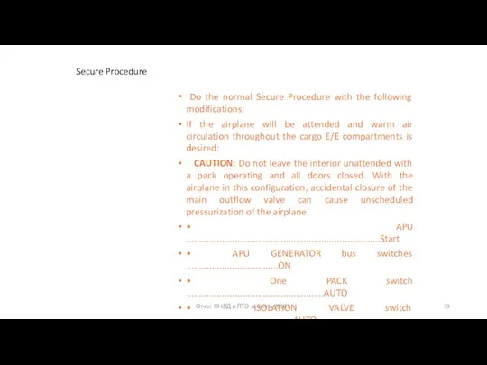
- 39. Secure Procedure Do the normal Secure Procedure with the following modifications: If the airplane will be
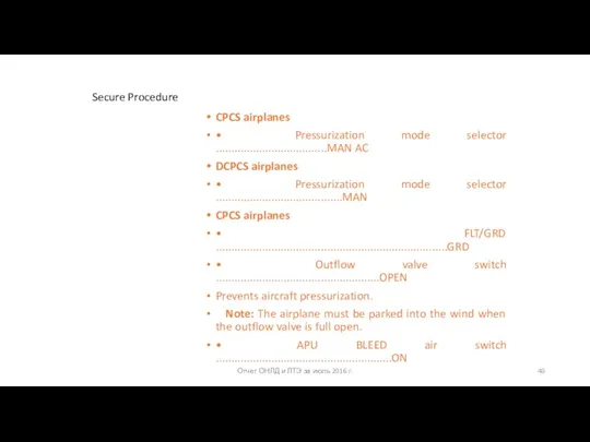
- 40. Secure Procedure CPCS airplanes • Pressurization mode selector ....................................MAN AC DCPCS airplanes • Pressurization mode selector
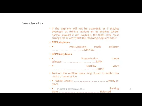
- 41. Secure Procedure If the airplane will not be attended, or if staying overnight at off-line stations
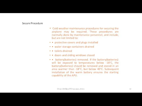
- 42. Secure Procedure Cold weather maintenance procedures for securing the airplane may be required. These procedures are
- 44. Скачать презентацию
Слайд 3Cold Weather Operation-General
Considerations associated with cold weather operation are primarily concerned with low
Cold Weather Operation-General
Considerations associated with cold weather operation are primarily concerned with low
• visible moisture (clouds, fog with visibility of one statute mile (1600 m) or less, rain, snow, sleet, ice crystals, and so on) is present, or
• ice, snow, slush, or standing water is present on the ramps, taxiways, or runways.
CAUTION: Do not use nacelle anti-ice when OAT (on the ground) is above 10°C. Do not use nacelle or wing anti–ice when TAT (in flight) is above 10°C.
Слайд 4Operating Limitations
Engine ignition
Continuous ignition must be on (ENGINE START switch in the
Operating Limitations
Engine ignition
Continuous ignition must be on (ENGINE START switch in the
Fuel Minimum tank fuel temperature prior to takeoff and inflight is - 43°C for 737NG or 3°C above the fuel freezing point temperature, whichever is higher. Note: The use of Fuel System Icing Inhibitor additives does not change the minimum fuel tank temperature limit.
Слайд 5Учёт низкой температуры топлива
(Fuel Freeze Temperature)
В полете температура топлива постепенно снижается до
Учёт низкой температуры топлива
(Fuel Freeze Temperature)
В полете температура топлива постепенно снижается до
Слайд 6Учёт низкой температуры топлива
(Fuel Freeze Temperature)
Но дальнейшее снижение температуры топлива приводит к
Учёт низкой температуры топлива
(Fuel Freeze Temperature)
Но дальнейшее снижение температуры топлива приводит к
Температуры начала кристаллизации различных сортов топлива: JET A-40ºС; JET A1 - 47ºС; JET B - 50ºС; TС-1 и РТ - 50ºС
Заправка различными сортами топлива может привести к тому, что в баках ВС образуется смесь с неизвестной температурой начала кристаллизации. В связи с этим при подготовке к полёту не следует автоматически считать температурой начала кристаллизации топлива на борту температуру начала кристаллизации заправляемого перед полётом топлива. В данном случае температурой начала кристаллизации топлива на борту необходимо считать наивысшую из температур начала кристаллизации сорта топлива, заправляемого в 3 последовательных заправках.
Слайд 7Учёт низкой температуры топлива
(Fuel Freeze Temperature)
Так, например, в случае последовательных заправок топливом
Учёт низкой температуры топлива
(Fuel Freeze Temperature)
Так, например, в случае последовательных заправок топливом
В соответствии с установленными ограничениями, на всех ВС фирмы Боинг, эксплуатируемых в АК, не допускается в полете понижение температуры топлива до величины выше на три градуса Цельсия температуры начала кристаллизации топлива.
Ниже приведена таблица значений ТАТ в зависимости от скорости полёта и температуры окружающего воздуха.
Слайд 8Учет низкой температуры топлива (Fuel Freeze Temperature)
SAT/TAT Conversion Table
Учет низкой температуры топлива (Fuel Freeze Temperature)
SAT/TAT Conversion Table
Слайд 9Учёт низкой температуры топлива
(Fuel Freeze Temperature)
На этапе расчета OFP и предполетной подготовки
Учёт низкой температуры топлива
(Fuel Freeze Temperature)
На этапе расчета OFP и предполетной подготовки
• Беря во внимание географию выполнения рейсов, для анализа возможной кристаллизации топлива в полете в зимнее время, рассматривать марку топлива JET A1.
• Учитывать ограничения по температуре кристаллизации топлива. При планировании полета значение ТАТ должно быть на 4º выше начала кристаллизации топлива (один градус добавляется на точность прогноза).
• Определить прогнозируемое значение ТАТ по OFP для тех поворотных пунктов, над которыми прогнозируется температура наружного воздуха (SAT/OAT) ниже -64ºС.
Прогнозируемое значение ТАТ определяется по таблице «SAT/TAT Conversion Table» по значению прогнозируемой SAT над ППМ и расчетному числу М.
Слайд 10Действия экипажа в полете
Учитывать тенденцию к снижению температуры топлива в баках до
Действия экипажа в полете
Учитывать тенденцию к снижению температуры топлива в баках до
• увеличение (по возможности) числа М полета. Увеличение числа М на 0.01 приводит к повышению ТАТ на 0.5 – 0.7°С. В данном случае необходимо учесть, что изменение температуры топлива при изменении ТАТ проявляется в течение от 15 минут до 60 минут;
• изменение маршрута полета в сторону более теплых воздушных масс;
• снижение до более теплых воздушных масс. Обычно отклонение от оптимального эшелона составляет 3000-5000 футов.
При экстремально низких температурах, возможно, потребуется снижение до 25000 футов.
Отчет ОНЛД и ЛТЭ за июль 2016 г.
Слайд 11Cold Weather Operation Exterior Inspection
Although removal of surface snow, ice, and frost is
Cold Weather Operation Exterior Inspection
Although removal of surface snow, ice, and frost is
Surfaces ........................................................Check
Takeoff with light coatings of frost, up to 1/8 inch (3mm) in thickness, on lower wing surfaces due to cold fuel is allowable; however, all leading edge devices, all control surfaces, and upper wing surfaces must be free of snow, ice and frost. Thin hoarfrost is acceptable on the upper surface of the fuselage provided all vents and ports are clear. Thin hoarfrost is a uniform white deposit of fine crystalline texture, which usually occurs on exposed surfaces on a cold and cloudless night, and which is thin enough to distinguish surface features underneath, such as paint lines, markings, or lettering.
Слайд 12Cold Weather Operation Exterior Inspection
Airplanes 737NG with Defined Cold-Soaked Fuel Frost Area
Visually
Cold Weather Operation Exterior Inspection
Airplanes 737NG with Defined Cold-Soaked Fuel Frost Area
Visually
Takeoff with light coatings of frost on upper wing surfaces due to cold fuel (cold-soaked fuel frost) is allowable, provided the following conditions are met:
• the frost on the upper surface is less than 1/16 inch (1.5 mm) in thickness
• the extent of the frost is similar on both wings
• the frost is on or between the black lines defining the allowable cold-soaked fuel frost area with no ice or frost on the leading edges or control surfaces
• the ambient air temperature is above freezing (0°C, 32°F)
• there is no precipitation or visible moisture (rain, snow, drizzle or fog with less than 1 mile visibility, etc.).
Слайд 13Cold Weather Operation Exterior Inspection
If all the above criteria are not met,
Cold Weather Operation Exterior Inspection
If all the above criteria are not met,
Note: If the frost on the lower surface is less than 1/16 inch (1.5 mm) in thickness, the frost on the upper surface will be less than 1/16 inch (1.5 mm) in thickness.
• Control surface balance panel cavities ..............................Check
Check drainage after snow removal. Puddled water may freeze in flight.
• Pitot probes and static ports …...........................................Check
Verify that all pitot probes and static ports are free of snow or ice. Water rundown after snow removal may freeze immediately forward of static ports and cause an ice buildup which disturbs airflow over the static ports resulting in erroneous static readings even when the static ports are clear.
• Air conditioning inlets and exits ..........................................Clear
Verify that the air inlets and exits, including the outflow valves, are clear of snow or ice. If the APU is operating, verify that the outflow valve is fully open.
Слайд 14Cold Weather Operation Exterior Inspection
• Engine inlets ...............................................................Check
Verify that the inlet cowling is
Cold Weather Operation Exterior Inspection
• Engine inlets ...............................................................Check
Verify that the inlet cowling is
• Fuel tank vents .......................................................... Check
Verify all traces of ice and frost are removed.
• Landing gear doors .................................................... Check
Landing gear doors should be free of snow and ice.
• APU air inlets ............................................................. Check
The APU inlet door and cooling air inlet must be free of snow and ice before APU start.
Слайд 15Температура в салонах
К моменту посадки пассажиров температура воздуха в салоне должна быть не
Температура в салонах
К моменту посадки пассажиров температура воздуха в салоне должна быть не
Слайд 16De-icing / Anti-icing Procedure
Testing of undiluted de-icing/anti-icing fluids has shown that some of
De-icing / Anti-icing Procedure
Testing of undiluted de-icing/anti-icing fluids has shown that some of
CAUTION: Operate the APU during de-icing only if necessary.
If the APU is running, ingestion of de-icing fluid causes objectionable fumes and odors to enter the airplane. Ingestion of snow, slush, ice, or de-icing/anti-icing fluid can also cause damage to the APU.
If de-icing/anti-icing is needed:
• APU ...........................................................As needed
The APU should be shut down unless APU operation is necessary.
Слайд 17De-icing / Anti-icing Procedure
Call “FLAPS UP”.
Flaps........................................................................UP
Prevents ice and slush from accumulating
De-icing / Anti-icing Procedure
Call “FLAPS UP”.
Flaps........................................................................UP
Prevents ice and slush from accumulating
Thrust levers...........................................................Idle
Reduces the possibility of injury to personnel at inlet or exhaust areas.
WARNING: Ensure that the stabilizer trim wheel handles are stowed before using electric trim to avoid personal injury.
Stabilizer trim........................................... ____UNITS
Set the trim for takeoff.
Verify that the trim is in the green band.
Слайд 18De-icing / Anti-icing Procedure
• Engine BLEED air switches .....................................OFF
Reduces the possibility
De-icing / Anti-icing Procedure
• Engine BLEED air switches .....................................OFF
Reduces the possibility
• APU BLEED air switch ............................................OFF
Reduces the possibility of fumes entering the air conditioning system. After de-icing/anti-icing is completed:
• APU .............................................................As needed
Wait approximately one minute after de-icing is completed to turn engine BLEED air switches on to ensure all de-icing fluid has been cleared from the engines:
• Engine BLEED air switches………………..……………......ON
Слайд 19Engine Start Procedure
Do the normal Engine Start Procedure with the following modifications:
•
Engine Start Procedure
Do the normal Engine Start Procedure with the following modifications:
•
• Several minutes may be needed for oil pressure to reach the normal operating pressure. During this period, oil pressure may go above the normal range and the FILTER BYPASS light may illuminate. Operate the engine at idle thrust until oil pressure returns to the normal range.
• If the oil pressure remains above the normal range after the oil temperature has stabilized within limits, shut down the engine.
Слайд 20Engine Start Procedure
• If the engine has been cold soaked for one or
Engine Start Procedure
• If the engine has been cold soaked for one or
• If the engine has been cold soaked for three or more hours at ambient temperatures below -40°C, do not start or motor the engine. Maintenance personnel should do appropriate procedures for adverse weather starter servicing.
• Display units may require additional warm-up time before displayed engine indications accurately show changing values.
• Display units may appear less bright than normal.
Слайд 21Engine Anti–Ice Operation On the Ground
Engine anti-ice must be selected ON immediately
Engine Anti–Ice Operation On the Ground
Engine anti-ice must be selected ON immediately
WARNING: Do not rely on airframe visual icing cues before activating engine anti-ice. Use the temperature and visible moisture criteria because late activation of engine anti-ice may allow excessive ingestion of ice and result in engine damage or failure.
CAUTION: Do not use engine anti-ice when OAT is above 10°C.
.
Слайд 22Engine Anti–Ice Operation On the Ground
.
When engine anti-ice is needed:
• ENGINE
Engine Anti–Ice Operation On the Ground
.
When engine anti-ice is needed:
• ENGINE
• ENGINE ANTI-ICE switches ....................................ON
Verify that the COWL VALVE OPEN lights illuminate bright, then dim. Verify that the COWL ANTI-ICE lights are extinguished.
Note: If the COWL VALVE OPEN lights remain illuminated bright with engines at IDLE, position APU BLEED air switch to OFF and increase thrust slightly (up to a maximum of 30% N1). When engine anti-ice is no longer needed:
• ENGINE ANTI-ICE switches ...................................OFF
Verify that the COWL VALVE OPEN lights illuminate bright, then extinguish.
Слайд 23Before Taxi Procedure
.
Отчет ОНЛД и ЛТЭ за июль 2016 г.
Do the normal Before
Before Taxi Procedure
.
Отчет ОНЛД и ЛТЭ за июль 2016 г.
Do the normal Before
• GENERATOR 1 and 2 switches ..........................................ON
Normally the IDG’s will stabilize within one minute, although due to cold oil, up to five minutes may be needed to produce steady power.
• Flight controls ...............................................................Check
An increase in control forces can be expected at low temperatures.
CAUTION: The flap position indicator and the leading edge devices annunciator panel should be closely observed for positive movement. If the flaps should stop, the flap lever should be placed immediately in the same position as indicated.
• Flaps .............................................................................Check
Move the flaps from Flaps up to Flaps 40 back to Flaps up (i.e., full travel) to ensure freedom of movement.
Слайд 24Before Taxi Procedure
.
Отчет ОНЛД и ЛТЭ за июль 2016 г.
If taxi route
Before Taxi Procedure
.
Отчет ОНЛД и ЛТЭ за июль 2016 г.
If taxi route
Call “FLAPS ___”………...……..………………………….… as needed
• Flap lever ..........................................Set flaps, as needed
Слайд 25
Taxi-Out Procedure
When engine anti-ice is required and the OAT is 3°C or below,
Taxi-Out Procedure
When engine anti-ice is required and the OAT is 3°C or below,
Check that the area behind the airplane is clear. Run-up to a minimum of 70% N1 for approximately 30 seconds duration at intervals no greater than 30 minutes.
Note: Fan blade ice build up is cumulative. If the fan spinner and fan blades were not deiced prior to taxi out, the time the engines were operating during the taxi in should be included in the 30 minute interval.
If airport surface conditions and the concentration of aircraft do not allow the engine thrust level to be increased to 70% N1, then set a thrust level as high as practical and time at that thrust level.
Note: When operating in conditions of freezing rain, freezing drizzle, freezing fog or heavy snow, run-ups to a minimum of 70% N1 for approximately 1 second duration at intervals no greater than 10 minutes enhance ice shedding.
Отчет ОНЛД и ЛТЭ за июль 2016 г.
Слайд 26Takeoff Procedure
Do the normal Takeoff Procedure with the following modification:
When engine
Takeoff Procedure
Do the normal Takeoff Procedure with the following modification:
When engine
• Run-up to a minimum of 70% N1 and confirm stable engine operation before the start of the takeoff roll. A 30-second run-up is highly recommended whenever possible.
Отчет ОНЛД и ЛТЭ за июль 2016 г.
Слайд 27
Engine Anti-Ice Operation - In Flight
Engine anti–ice must be ON during all flight
Engine Anti-Ice Operation - In Flight
Engine anti–ice must be ON during all flight
WARNING: Do not rely on airframe visual icing cues before activating engine anti–ice. Use the temperature and visible moisture criteria because late activation of engine anti-ice may allow excessive ingestion of ice and result in engine damage or failure.
CAUTION: Do not use engine anti-ice when TAT is above 10°C.
Отчет ОНЛД и ЛТЭ за июль 2016 г.
Слайд 28
Engine Anti-Ice Operation - In Flight
When engine anti-ice is needed:
• ENGINE START
Engine Anti-Ice Operation - In Flight
When engine anti-ice is needed:
• ENGINE START
• ENGINE ANTI-ICE switches .....................................ON
Verify that the COWL VALVE OPEN lights illuminate bright, then dim.
Verify that the COWL ANTI-ICE lights are extinguished.
Note: If the COWL VALVE OPEN lights remain illuminated bright with engines at IDLE, increase thrust slightly (up to a minimum of 30% N1).
When engine anti-ice is no longer needed:
• ENGINE ANTI-ICE switches ....................................OFF
Verify that the COWL VALVE OPEN lights illuminate bright, then extinguish.
Отчет ОНЛД и ЛТЭ за июль 2016 г.
Слайд 29Fan Ice Removal
CAUTION: Avoid prolonged operation in moderate to severe icing conditions.
Fan Ice Removal
CAUTION: Avoid prolonged operation in moderate to severe icing conditions.
Severe icing can usually be avoided by a change in altitude and/or airspeed. If flight in moderate to severe icing conditions cannot be avoided, do the following on both engines, one engine at a time at approximately 15 minute intervals:
• Thrust ................................................................Increase
Increase thrust to a minimum of 80% N1 for approximately 1 second to ensure the fan blades and spinner are clear of ice. Engine vibration may occur due to fan blade/spinner icing.
Слайд 30Fan Ice Removal
If engine vibration continues after increasing thrust, do the following
Fan Ice Removal
If engine vibration continues after increasing thrust, do the following
• ENGINE START switch ...............................................FLT
• Thrust ..................................................................Adjust
Adjust thrust to 45% N1. After approximately five seconds, increase thrust lever slowly to a minimum of 80% N1.
Note: Engine vibration may reduce to a low level before 80% N1 is reached, however, thrust increase must continue to a minimum of 80% N1 to remove ice from the fan blades.
Note: Engine vibration may indicate full scale prior to shedding ice, however, this has no adverse effect on the engine.
If vibration does not decrease, do the procedure for HIGH ENGINE VIBRATION “If not in icing conditions.”
Слайд 31
Wing Anti-Ice Operation In Flight
Отчет ОНЛД и ЛТЭ за июль 2016 г.
Wing Anti-Ice Operation In Flight
Отчет ОНЛД и ЛТЭ за июль 2016 г.
In flight, the wing anti-ice system may be used as a deicer or as an anti-icer.
The primary method is to use it as a de-icer by allowing ice to accumulate before turning wing anti-ice on. This procedure provides the cleanest airfoil surface, the least possible runback ice formation, and the least thrust and fuel penalty. Normally it is not necessary to shed ice periodically unless extended flight through icing conditions is necessary (holding).
The secondary method is to use wing anti-ice before ice accumulation. Operate the wing anti-ice system as an anti-icer only during extended operations in moderate or severe icing conditions, such as holding.
Слайд 32
Wing Anti-Ice Operation In Flight
Отчет ОНЛД и ЛТЭ за июль 2016 г.
Wing Anti-Ice Operation In Flight
Отчет ОНЛД и ЛТЭ за июль 2016 г.
CAUTION: Use of wing anti-ice above approximately FL350 may cause bleed trip off and possible loss of cabin pressure.
Note: Prolonged operation in icing conditions with the leading edge and trailing edge flaps extended is not recommended. Holding in icing conditions with flaps extended is prohibited.
When wing anti-ice is needed:
• WING ANTI-ICE switch ....................................................ON
Verify that the L and R VALVE OPEN lights illuminate bright, then dim.
When wing anti-ice is no longer needed:
• WING ANTI-ICE switch .................................................. OFF
Verify that the L and R VALVE OPEN lights illuminate bright, then extinguish.
Слайд 33Approach and Landing
For 737 NG airplanes:
Use normal procedures and reference
Approach and Landing
For 737 NG airplanes:
Use normal procedures and reference
- If a flaps 15 landing will be made: Set VREF 15.
- If any of the following conditions apply, set VREF ICE = VREF 15 + 10:
• engine anti–ice will be used during landing
• wing anti–ice has been used any time during the flight
• icing conditions were encountered during the flight and the landing temperature is below 10°C.
Отчет ОНЛД и ЛТЭ за июль 2016 г.
Слайд 34After Landing Procedure
CAUTION: Taxi at a reduced speed. Use smaller nose wheel
After Landing Procedure
CAUTION: Taxi at a reduced speed. Use smaller nose wheel
CAUTION: When operating the engines over significant amounts of standing de-icing or anti-icing fluid, limit thrust to the minimum required. Excessive ingestion of de-icing or anti-icing fluid can cause the fluid to build up on the engine compressor blades resulting in compressor stalls and engine surges.
Отчет ОНЛД и ЛТЭ за июль 2016 г.
Слайд 35After Landing Procedure
Do the normal After Landing Procedure with the following modifications:
After Landing Procedure
Do the normal After Landing Procedure with the following modifications:
After prolonged operation in icing conditions with the flaps extended, or when an accumulation of airframe ice is observed, or when operating on a runway or taxiway contaminated with ice, snow, slush or standing water:
Do not retract the flaps until the flap areas have been checked to be free of contaminants.
Engine anti-ice must be selected ON and remain on during all ground operations when icing conditions exist or are anticipated, except when the temperature is below –40°C OAT.
Отчет ОНЛД и ЛТЭ за июль 2016 г.
Слайд 36After Landing Procedure
CAUTION: Do not use engine anti-ice when OAT is above
After Landing Procedure
CAUTION: Do not use engine anti-ice when OAT is above
• ENGINE START switches ...........................................CONT
• ENGINE ANTI-ICE switches .....................................ON Verify that the COWL VALVE OPEN lights illuminate bright, then dim.
Verify that the COWL ANTI-ICE lights are extinguished.
Note: If the COWL VALVE OPEN lights remain illuminated bright with engines at IDLE, increase thrust slightly (up to a maximum of 30% N1).
When engine anti-ice is no longer needed:
• ENGINE ANTI-ICE switches .......................................... OFF
Verify that the COWL VALVE OPEN lights illuminate bright, then extinguish.
• ENGINE START switches .............................................. OFF
Отчет ОНЛД и ЛТЭ за июль 2016 г.
Слайд 37After Landing Procedure
When engine anti-ice is required and the OAT is 3°C
After Landing Procedure
When engine anti-ice is required and the OAT is 3°C
• Check that the area behind the airplane is clear. Run-up to a minimum of 70% N1 for approximately 30 seconds duration at intervals no greater than 30 minutes.
• If airport surface conditions and the concentration of aircraft do not allow the engine thrust level to be increased to 70% N1, then set a thrust level as high as practical and time at that thrust level.
Note: When operating in conditions of freezing rain, freezing drizzle, freezing fog or heavy snow, run-ups to a minimum of 70% N1 for approximately 1 second duration at intervals no greater then 10 minutes should be considered.
Отчет ОНЛД и ЛТЭ за июль 2016 г.
Слайд 38Shutdown Procedure
After landing in icing conditions do the following step before starting
Shutdown Procedure
After landing in icing conditions do the following step before starting
WARNING: Ensure that the stabilizer trim wheel handles are stowed before using electric trim to avoid personal injury.
• Stabilizer trim....................................................... Set 5 units
Prevents melting snow and ice from running into balance bay areas. Water in these areas can freeze and lock controls.
Отчет ОНЛД и ЛТЭ за июль 2016 г.
Слайд 39Secure Procedure
Do the normal Secure Procedure with the following modifications:
If the
Secure Procedure
Do the normal Secure Procedure with the following modifications:
If the
CAUTION: Do not leave the interior unattended with a pack operating and all doors closed. With the airplane in this configuration, accidental closure of the main outflow valve can cause unscheduled pressurization of the airplane.
• APU ............................................................................Start
• APU GENERATOR bus switches ....................................ON
• One PACK switch ......................................................AUTO
• ISOLATION VALVE switch ..........................................AUTO
Отчет ОНЛД и ЛТЭ за июль 2016 г.
Слайд 40Secure Procedure
CPCS airplanes
• Pressurization mode selector ....................................MAN AC
DCPCS airplanes
• Pressurization
Secure Procedure
CPCS airplanes
• Pressurization mode selector ....................................MAN AC
DCPCS airplanes
• Pressurization
CPCS airplanes
• FLT/GRD ...........................................................................GRD
• Outflow valve switch .....................................................OPEN
Prevents aircraft pressurization.
Note: The airplane must be parked into the wind when the outflow valve is full open.
• APU BLEED air switch .........................................................ON
Отчет ОНЛД и ЛТЭ за июль 2016 г.
Слайд 41Secure Procedure
If the airplane will not be attended, or if staying overnight at
Secure Procedure
If the airplane will not be attended, or if staying overnight at
CPCS airplanes
• Pressurization mode selector …………………………....MAN AC
DCPCS airplanes
• Pressurization mode selector………...........……………....MAN
• Outflow valve ............................................................CLOSE
Position the outflow valve fully closed to inhibit the intake of snow or ice.
• Wheel chocks ...............................................Verify in place
• Parking brake........................................................Released
Reduces the possibility of frozen brakes.
Отчет ОНЛД и ЛТЭ за июль 2016 г.
Слайд 42Secure Procedure
Cold weather maintenance procedures for securing the airplane may be required.
Secure Procedure
Cold weather maintenance procedures for securing the airplane may be required.
• protective covers and plugs installed
• water storage containers drained
• toilets drained
• doors and sliding windows closed
• battery(batteries) removed. If the battery(batteries) will be exposed to temperatures below -18°C, the battery(batteries) should be removed and stored in an area warmer than -18°C, but below 40°C. Subsequent installation of the warm battery ensures the starting capability of the APU.
Отчет ОНЛД и ЛТЭ за июль 2016 г.