- Design of UAV systems

Содержание
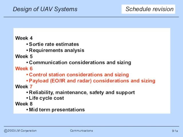
- 2. 9-1a Schedule revision Week 4 Sortie rate estimates Requirements analysis Week 5 Communication considerations and sizing
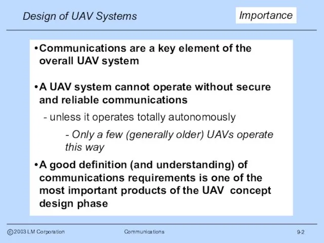
- 3. 9-2 Importance Communications are a key element of the overall UAV system A UAV system cannot
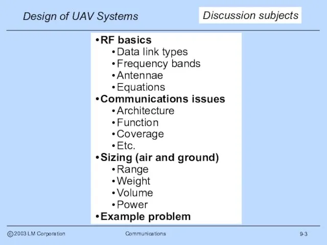
- 4. 9-3 RF basics Data link types Frequency bands Antennae Equations Communications issues Architecture Function Coverage Etc.
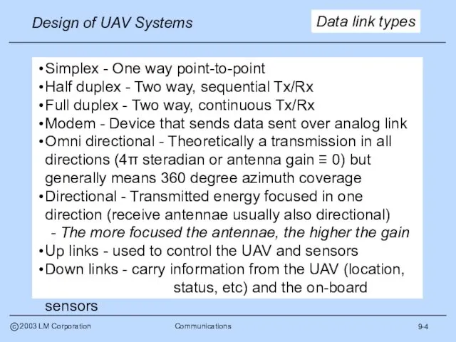
- 5. 9-4 Data link types Simplex - One way point-to-point Half duplex - Two way, sequential Tx/Rx
- 6. 9-5 Frequency bands
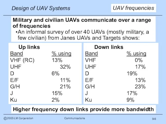
- 7. 9-6 UAV frequencies Military and civilian UAVs communicate over a range of frequencies An informal survey
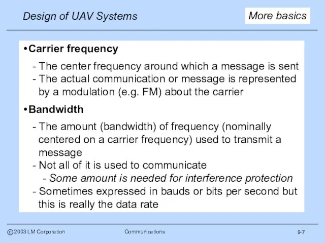
- 8. 9-7 More basics Carrier frequency - The center frequency around which a message is sent -
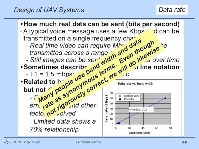
- 9. 9-8 Data rate Many people use band width and data rate as synonymous terms. Even though
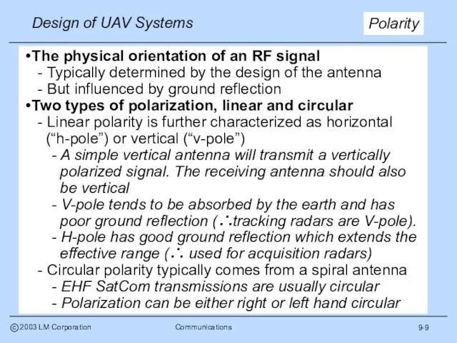
- 10. 9-9 Polarity The physical orientation of an RF signal - Typically determined by the design of
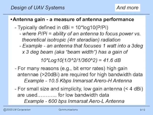
- 11. 9-10 And more Antenna gain - a measure of antenna performance - Typically defined in dBi
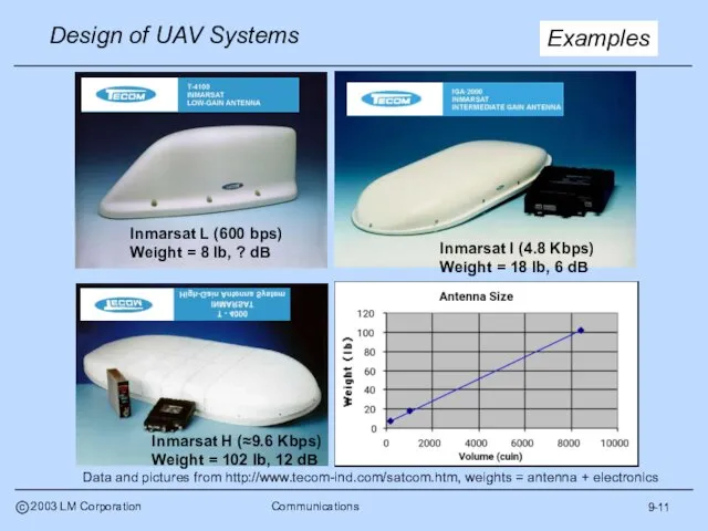
- 12. 9-11 Examples Inmarsat I (4.8 Kbps) Weight = 18 lb, 6 dB Data and pictures from
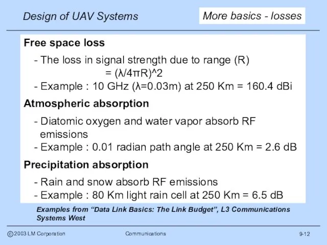
- 13. 9-12 More basics - losses Free space loss - The loss in signal strength due to
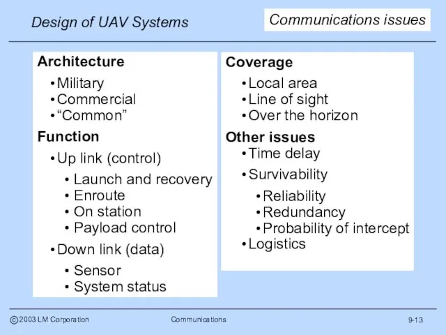
- 14. 9-13 Architecture Military Commercial “Common” Function Up link (control) Launch and recovery Enroute On station Payload
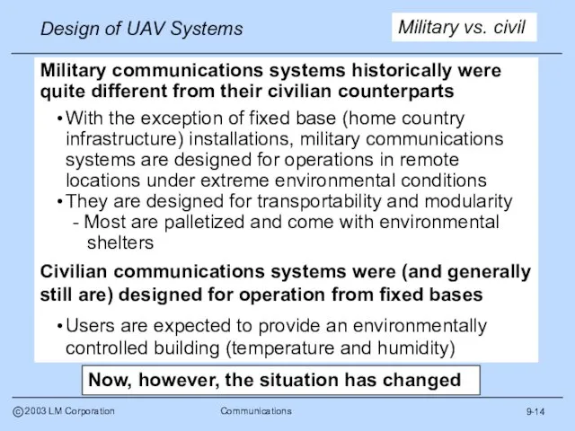
- 15. 9-14 Military vs. civil Military communications systems historically were quite different from their civilian counterparts With
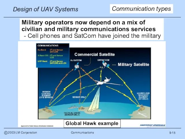
- 16. 9-15 Communication types Military operators now depend on a mix of civilian and military communications services
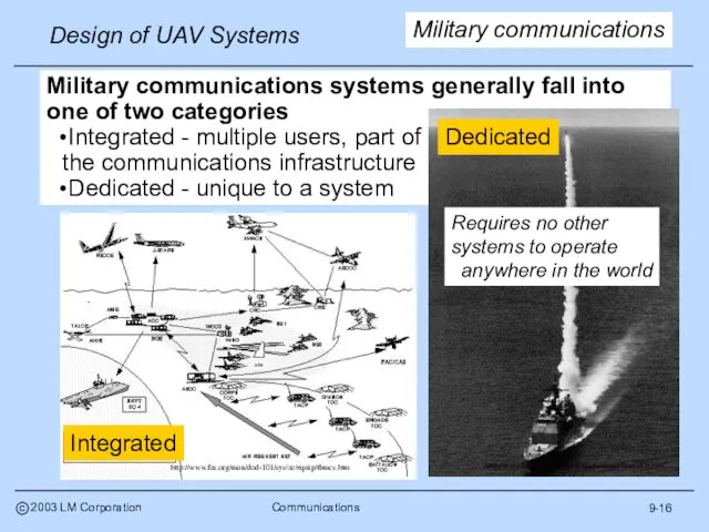
- 17. 9-16 Military communications Military communications systems generally fall into one of two categories Integrated - multiple
- 18. 9-17 UAV architectures UAV communication systems are generally dedicated The systems may have other applications (e.g.
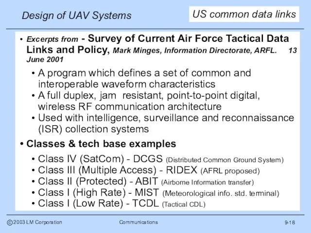
- 19. 9-18 US common data links Excerpts from - Survey of Current Air Force Tactical Data Links
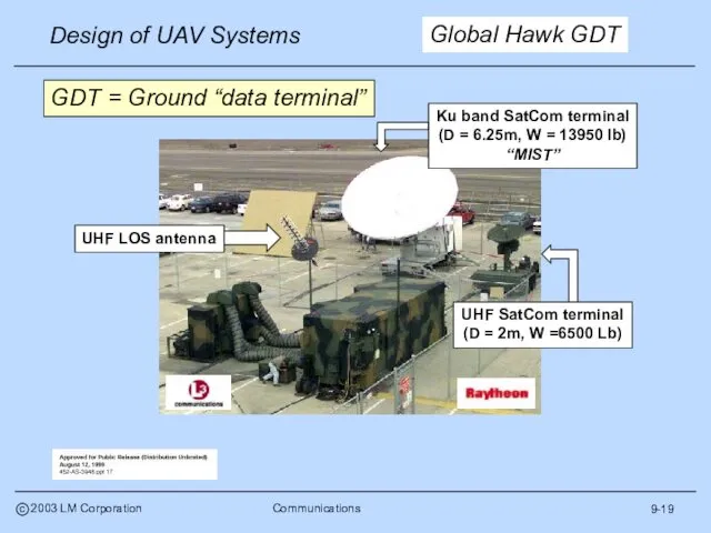
- 20. 9-19 Global Hawk GDT GDT = Ground “data terminal”
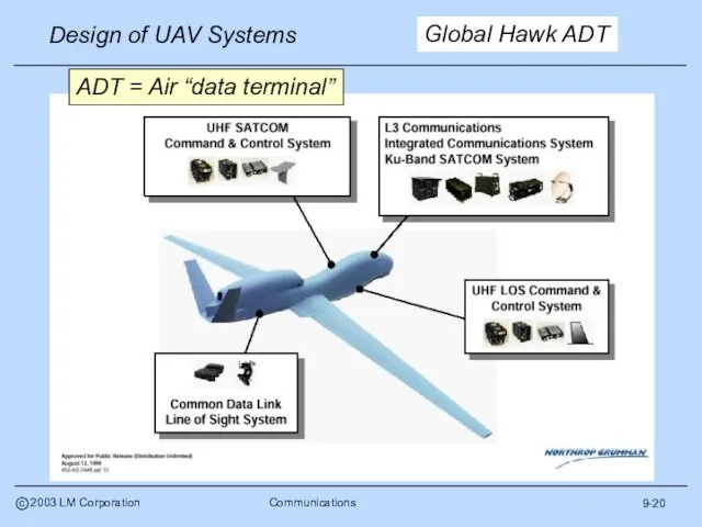
- 21. 9-20 Global Hawk ADT ADT = Air “data terminal”
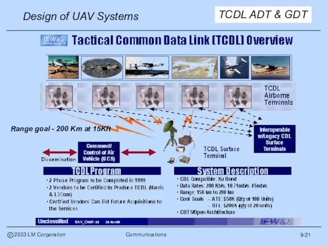
- 22. 9-21 TCDL ADT & GDT Range goal - 200 Km at 15Kft
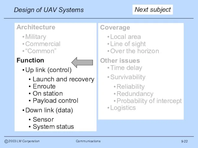
- 23. 9-22 Architecture Military Commercial “Common” Function Up link (control) Launch and recovery Enroute On station Payload
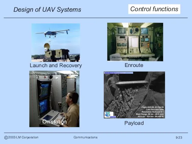
- 24. 9-23 Control functions
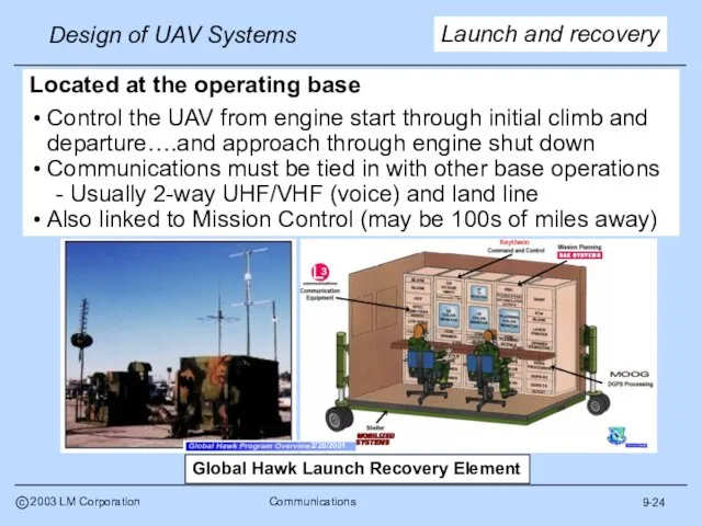
- 25. 9-24 Launch and recovery Located at the operating base Control the UAV from engine start through
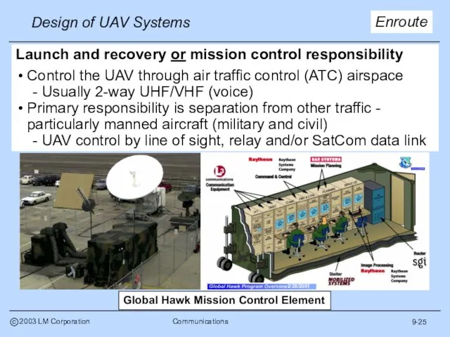
- 26. 9-25 Enroute Launch and recovery or mission control responsibility Control the UAV through air traffic control
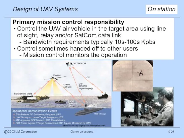
- 27. 9-26 On station Primary mission control responsibility Control the UAV air vehicle in the target area
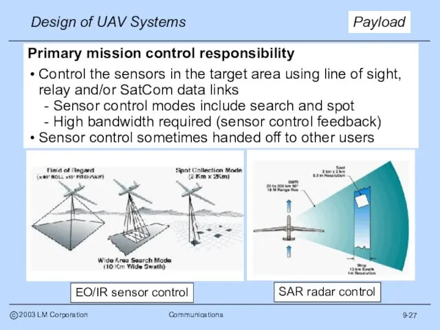
- 28. 9-27 Payload Primary mission control responsibility Control the sensors in the target area using line of
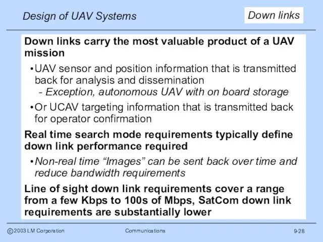
- 29. 9-28 Down links Down links carry the most valuable product of a UAV mission UAV sensor
- 30. 9-29 Radar “imagery” High resolution “imagery” (whether real or synthetic) establishes the down link bandwidth requirement
- 31. EO/IR data EO/IR requirements are for comparable areas and resolution. After compression, Global Hawk EO/IR bandwidth
- 32. 9-31 System status data Air vehicle system status requirements are small in comparison to sensors -
- 33. Coverage Local area Line of sight Over the horizon Other issues Time delay Survivability Reliability Redundancy
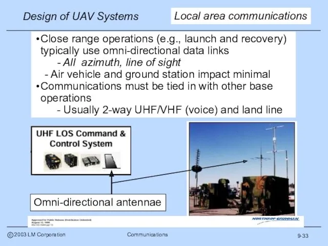
- 34. 9-33 Local area communications Close range operations (e.g., launch and recovery) typically use omni-directional data links
- 35. Typically require directional data links - RF focused on control station and/or air vehicle - Impact
- 36. Relay aircraft - existing line of sight equipment Minimal air vehicle design impact Major operational impact
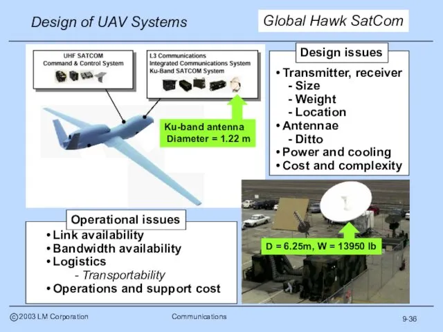
- 37. 9-36 Global Hawk SatCom
- 38. Coverage Local area Line of sight Over the horizon Other issues Time delay Survivability Reliability Redundancy
- 39. 9-38 The time required to transmit, execute and feed back a command (at the speed of
- 40. 9-39 Also known as data “latency” or “lag” - Limited by speed of light and “clock
- 41. 9-40 The preferred reliability solution Separate back up data link(s) Most modern UAVs have redundant data
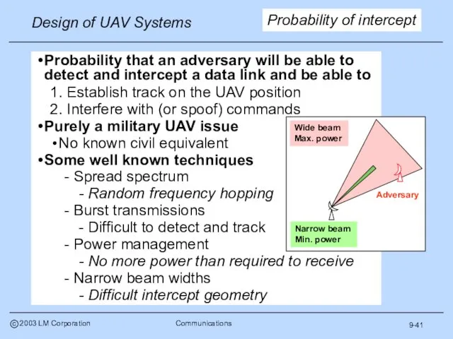
- 42. 9-41 Probability of intercept Probability that an adversary will be able to detect and intercept a
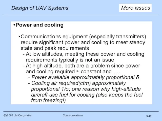
- 43. 9-42 More issues Power and cooling Communications equipment (especially transmitters) require significant power and cooling to
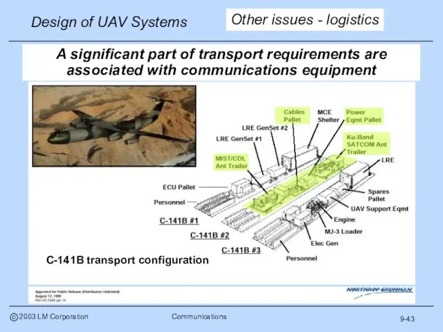
- 44. 9-43 A significant part of transport requirements are associated with communications equipment C-141B transport configuration Other
- 45. 9-44 Next subject RF basics Data link types Frequency bands Antennae Equations Communications issues Architecture Function
- 46. - Given 2 platforms at distance (D1+D2) apart at altitudes h1 and h2 above the surface
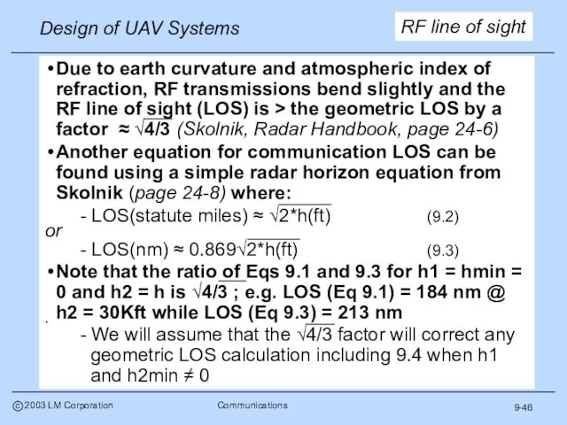
- 47. 9-46 RF line of sight Due to earth curvature and atmospheric index of refraction, RF transmissions
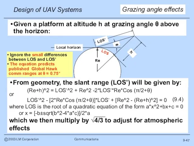
- 48. 9-47 Grazing angle effects Ignore the small differences between LOS and LOS’ The equation predicts published
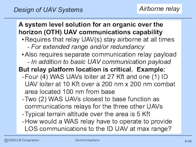
- 49. 9-48 Airborne relay A system level solution for an organic over the horizon (OTH) UAV communications
- 50. 9-49 LOS defines max communication distance for relay - At θ =0.75°, LOS from base =
- 51. 9-50 There is little public information available on UAV data links to use for initial sizing
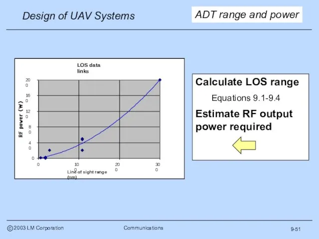
- 52. 9-51 ADT range and power Calculate LOS range Equations 9.1-9.4 Estimate RF output power required
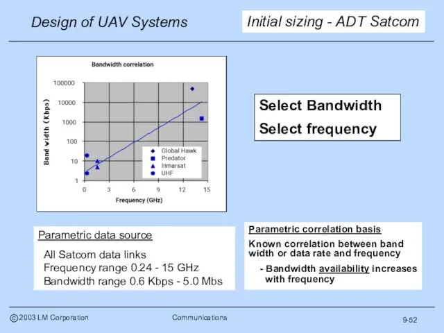
- 53. 9-52 Initial sizing - ADT Satcom Parametric correlation basis Known correlation between band width or data
- 54. 9-53 ADT power required Parametric data source Military line of sight data links Frequency range 30
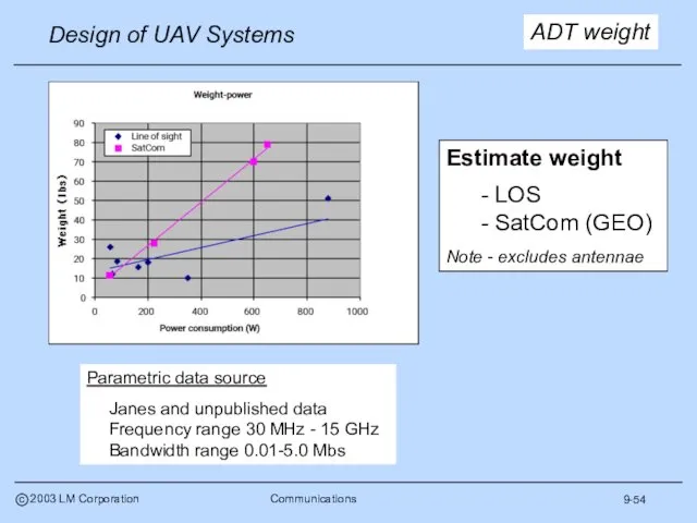
- 55. 9-54 ADT weight Parametric data source Janes and unpublished data Frequency range 30 MHz - 15
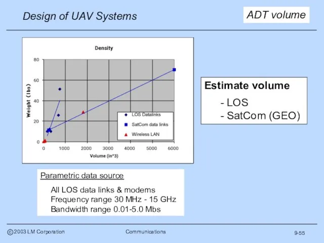
- 56. 9-55 ADT volume Parametric data source All LOS data links & modems Frequency range 30 MHz
- 57. Parametric correlation basis Known correlation between bandwidth required and size Antenna characteristic “size” defined as following:
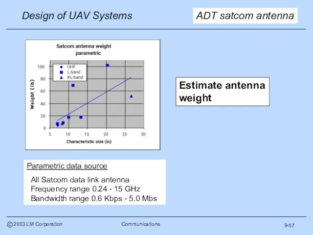
- 58. 9-57 ADT satcom antenna Parametric data source All Satcom data link antenna Frequency range 0.24 -
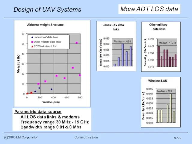
- 59. 9-58 More ADT LOS data Median = .025 Median = .045 Parametric data source All LOS
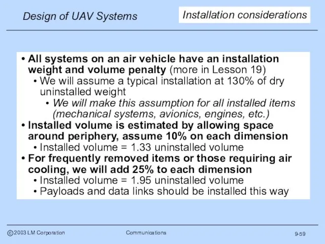
- 60. 9-59 All systems on an air vehicle have an installation weight and volume penalty (more in
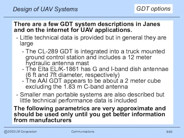
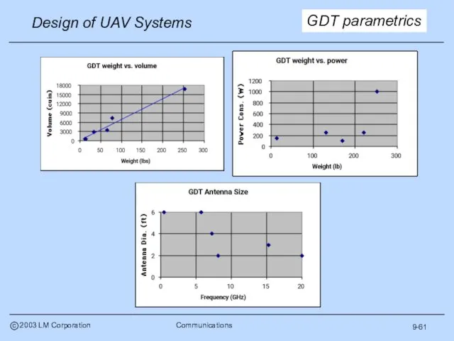
- 61. 9-60 GDT options There are a few GDT system descriptions in Janes and on the internet
- 62. 9-61 GDT parametrics
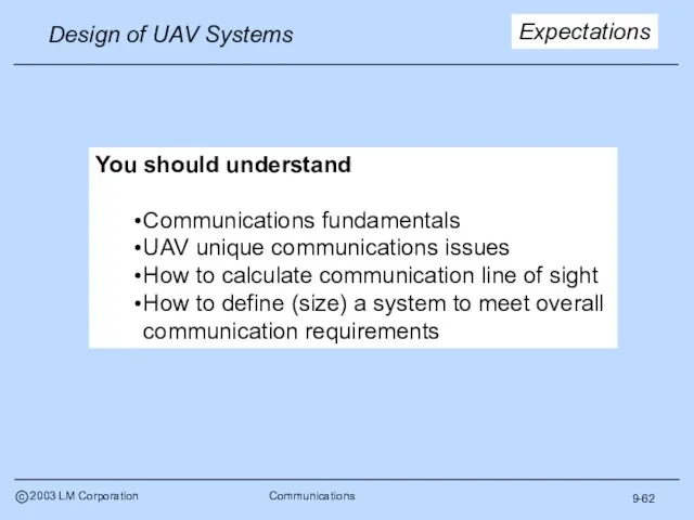
- 63. 9-62 Expectations You should understand Communications fundamentals UAV unique communications issues How to calculate communication line
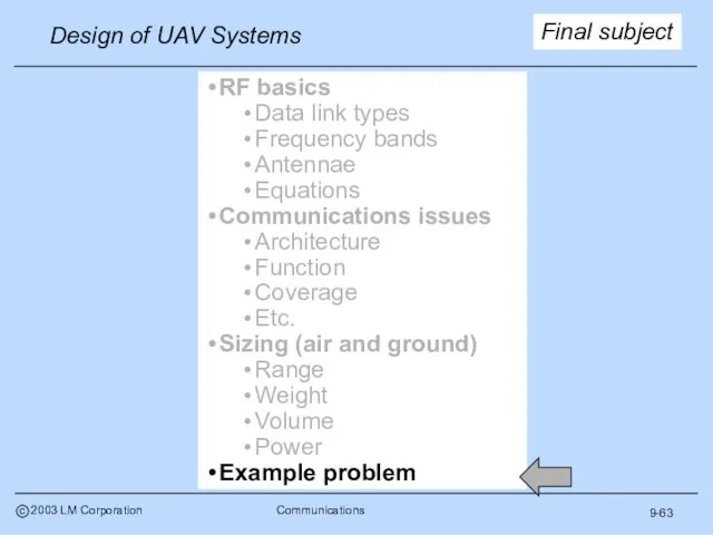
- 64. 9-63 Final subject RF basics Data link types Frequency bands Antennae Equations Communications issues Architecture Function
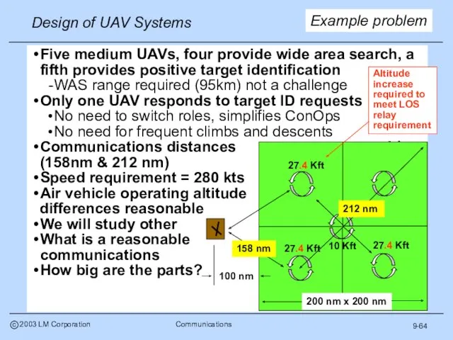
- 65. 9-64 Example problem Five medium UAVs, four provide wide area search, a fifth provides positive target
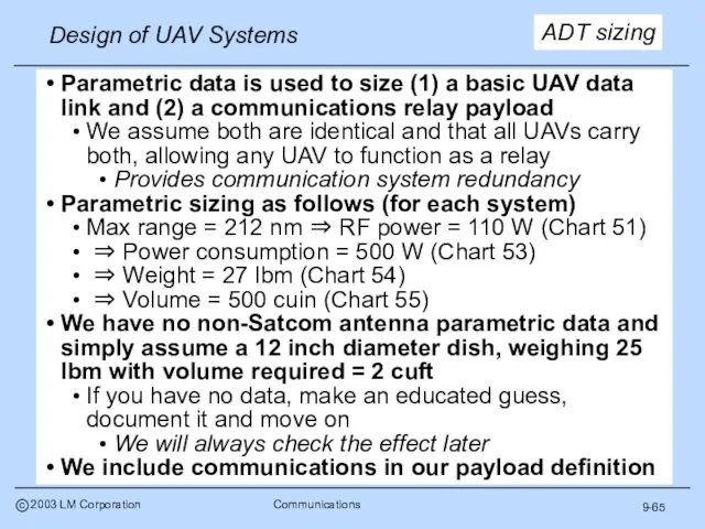
- 66. 9-65 Parametric data is used to size (1) a basic UAV data link and (2) a
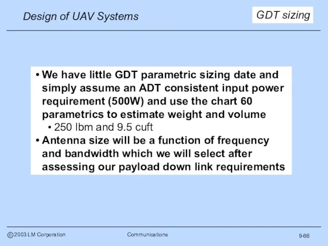
- 67. 9-66 We have little GDT parametric sizing date and simply assume an ADT consistent input power
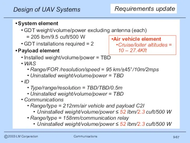
- 68. 9-67 Requirements update System element GDT weight/volume/power excluding antenna (each) = 205 lbm/9.5 cuft/500 W GDT
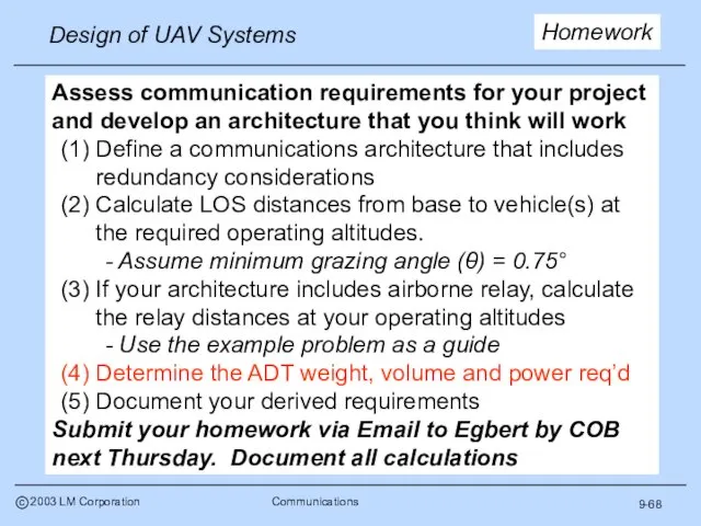
- 69. 9-68 Homework Assess communication requirements for your project and develop an architecture that you think will
- 71. Скачать презентацию
9-1a
Schedule revision
Week 4
Sortie rate estimates
Requirements analysis
Week 5
Communication considerations
9-1a
Schedule revision
Week 4
Sortie rate estimates
Requirements analysis
Week 5
Communication considerations
9-2
Importance
Communications are a key element of the overall UAV system
A UAV
9-2
Importance
Communications are a key element of the overall UAV system
A UAV
9-3
RF basics
Data link types
Frequency bands
Antennae
Equations
Communications issues
Architecture
Function
Coverage
Etc.
Sizing (air and ground)
Range
Weight
Volume
Power
Example problem
Discussion
9-3
RF basics
Data link types
Frequency bands
Antennae
Equations
Communications issues
Architecture
Function
Coverage
Etc.
Sizing (air and ground)
Range
Weight
Volume
Power
Example problem
Discussion
9-4
Data link types
Simplex - One way point-to-point
Half duplex - Two way,
9-4
Data link types
Simplex - One way point-to-point
Half duplex - Two way,
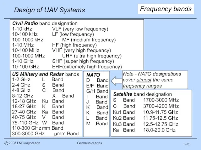
9-5
Frequency bands
9-5
Frequency bands
9-6
UAV frequencies
Military and civilian UAVs communicate over a range of frequencies
9-6
UAV frequencies
Military and civilian UAVs communicate over a range of frequencies
9-7
More basics
Carrier frequency
- The center frequency around which a message is
9-7
More basics
Carrier frequency
- The center frequency around which a message is
9-8
Data rate
Many people use band width and data rate as synonymous
9-8
Data rate
Many people use band width and data rate as synonymous
9-9
Polarity
The physical orientation of an RF signal
- Typically determined by the
9-9
Polarity
The physical orientation of an RF signal
- Typically determined by the
9-10
And more
Antenna gain - a measure of antenna performance
- Typically defined
9-10
And more
Antenna gain - a measure of antenna performance
- Typically defined
9-11
Examples
Inmarsat I (4.8 Kbps) Weight = 18 lb, 6 dB
Data and
9-11
Examples
Inmarsat I (4.8 Kbps) Weight = 18 lb, 6 dB
Data and
9-12
More basics - losses
Free space loss
- The loss in signal strength
9-12
More basics - losses
Free space loss
- The loss in signal strength
9-13
Architecture
Military
Commercial
“Common”
Function
Up link (control)
Launch and recovery
Enroute
On station
Payload control
Down link (data)
Sensor
System status
Communications
9-13
Architecture
Military
Commercial
“Common”
Function
Up link (control)
Launch and recovery
Enroute
On station
Payload control
Down link (data)
Sensor
System status
Communications
9-14
Military vs. civil
Military communications systems historically were quite different from
9-14
Military vs. civil
Military communications systems historically were quite different from
9-15
Communication types
Military operators now depend on a mix of civilian and
9-15
Communication types
Military operators now depend on a mix of civilian and
9-16
Military communications
Military communications systems generally fall into one of two categories
Integrated
9-16
Military communications
Military communications systems generally fall into one of two categories
Integrated
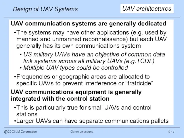
9-17
UAV architectures
UAV communication systems are generally dedicated
The systems may have other
9-17
UAV architectures
UAV communication systems are generally dedicated
The systems may have other
9-18
US common data links
Excerpts from - Survey of Current Air Force
9-18
US common data links
Excerpts from - Survey of Current Air Force
9-19
Global Hawk GDT
GDT = Ground “data terminal”
9-19
Global Hawk GDT
GDT = Ground “data terminal”
9-20
Global Hawk ADT
ADT = Air “data terminal”
9-20
Global Hawk ADT
ADT = Air “data terminal”
9-21
TCDL ADT & GDT
Range goal - 200 Km at 15Kft
9-21
TCDL ADT & GDT
Range goal - 200 Km at 15Kft
9-22
Architecture
Military
Commercial
“Common”
Function
Up link (control)
Launch and recovery
Enroute
On station
Payload control
Down link (data)
Sensor
System status
Next subject
Coverage
9-22
Architecture
Military
Commercial
“Common”
Function
Up link (control)
Launch and recovery
Enroute
On station
Payload control
Down link (data)
Sensor
System status
Next subject
Coverage
9-23
Control functions
9-23
Control functions
9-24
Launch and recovery
Located at the operating base
Control the UAV from
9-24
Launch and recovery
Located at the operating base
Control the UAV from
9-25
Enroute
Launch and recovery or mission control responsibility
Control the UAV through
9-25
Enroute
Launch and recovery or mission control responsibility
Control the UAV through
9-26
On station
Primary mission control responsibility
Control the UAV air vehicle in
9-26
On station
Primary mission control responsibility
Control the UAV air vehicle in
9-27
Payload
Primary mission control responsibility
Control the sensors in the target area
9-27
Payload
Primary mission control responsibility
Control the sensors in the target area
9-28
Down links
Down links carry the most valuable product of a UAV
9-28
Down links
Down links carry the most valuable product of a UAV
9-29
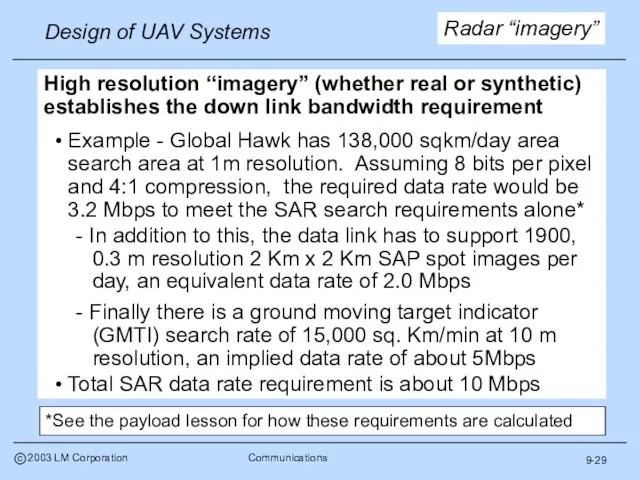
Radar “imagery”
High resolution “imagery” (whether real or synthetic) establishes the down
9-29
Radar “imagery”
High resolution “imagery” (whether real or synthetic) establishes the down
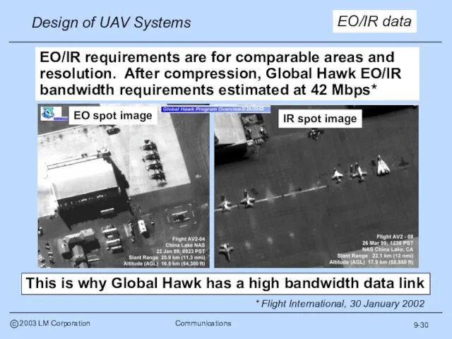
EO/IR data
EO/IR requirements are for comparable areas and resolution. After compression,
EO/IR data
EO/IR requirements are for comparable areas and resolution. After compression,
9-31
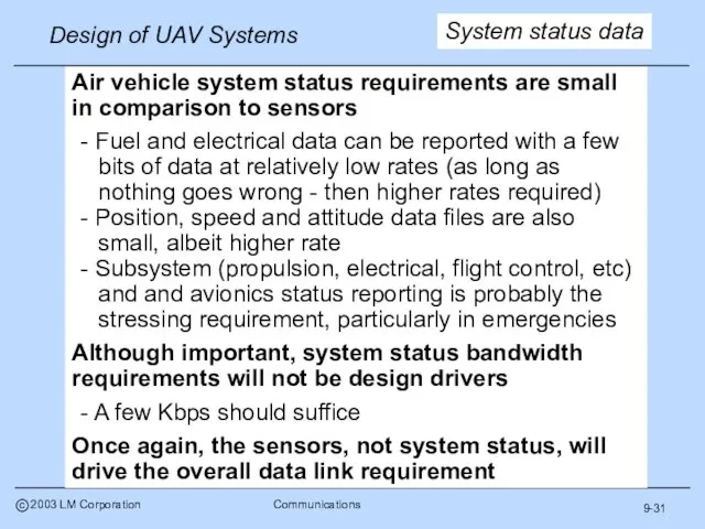
System status data
Air vehicle system status requirements are small in comparison
9-31
System status data
Air vehicle system status requirements are small in comparison
Coverage
Local area
Line of sight
Over the horizon
Other issues
Time delay
Survivability
Reliability
Redundancy
Probability of intercept
Logistics
9-32
Next
Coverage
Local area
Line of sight
Over the horizon
Other issues
Time delay
Survivability
Reliability
Redundancy
Probability of intercept
Logistics
9-32
Next
9-33
Local area communications
Close range operations (e.g., launch and recovery) typically use
9-33
Local area communications
Close range operations (e.g., launch and recovery) typically use
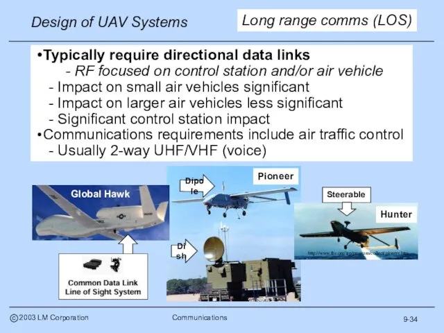
Typically require directional data links
- RF focused on control station
Typically require directional data links
- RF focused on control station
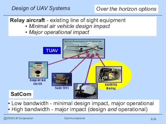
Relay aircraft - existing line of sight equipment
Minimal air vehicle design
Relay aircraft - existing line of sight equipment
Minimal air vehicle design
9-36
Global Hawk SatCom
9-36
Global Hawk SatCom
Coverage
Local area
Line of sight
Over the horizon
Other issues
Time delay
Survivability
Reliability
Redundancy
Probability of intercept
Logistics
9-37
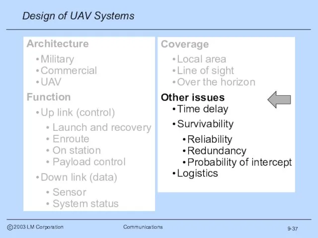
Architecture
Military
Commercial
UAV
Function
Up
Coverage
Local area
Line of sight
Over the horizon
Other issues
Time delay
Survivability
Reliability
Redundancy
Probability of intercept
Logistics
9-37
Architecture
Military
Commercial
UAV
Function
Up
9-38
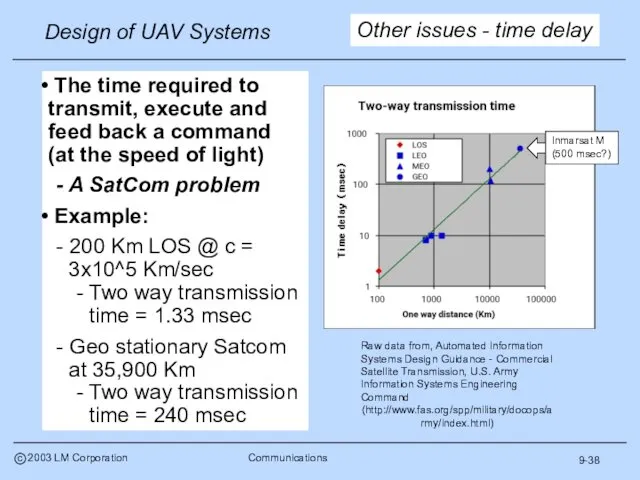
The time required to transmit, execute and feed back a
9-38
The time required to transmit, execute and feed back a
9-39
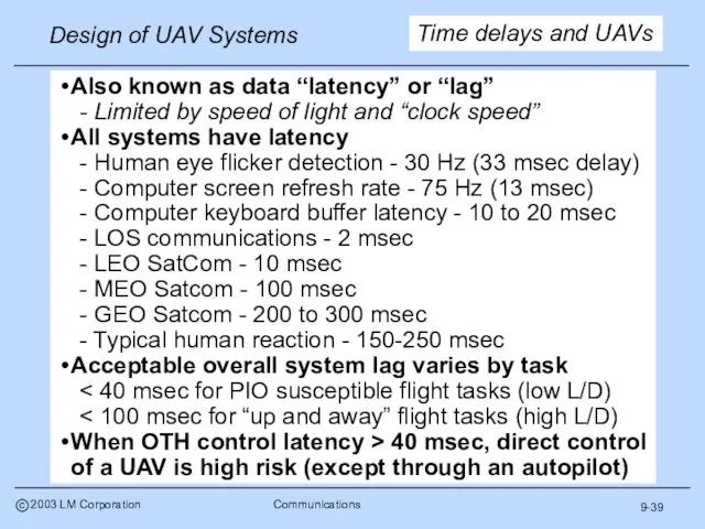
Also known as data “latency” or “lag”
- Limited by speed of
9-39
Also known as data “latency” or “lag”
- Limited by speed of
9-40
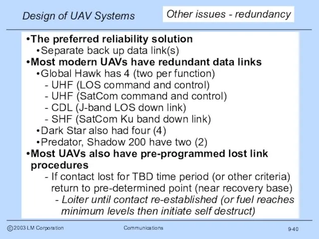
The preferred reliability solution
Separate back up data link(s)
Most modern UAVs have
9-40
The preferred reliability solution
Separate back up data link(s)
Most modern UAVs have
9-41
Probability of intercept
Probability that an adversary will be able to detect
9-41
Probability of intercept
Probability that an adversary will be able to detect
9-42
More issues
Power and cooling
Communications equipment (especially transmitters) require significant power and
9-42
More issues
Power and cooling
Communications equipment (especially transmitters) require significant power and
9-43
A significant part of transport requirements are associated with communications equipment
C-141B
9-43
A significant part of transport requirements are associated with communications equipment
C-141B
9-44
Next subject
RF basics
Data link types
Frequency bands
Antennae
Equations
Communications issues
Architecture
Function
Coverage
Etc.
Sizing (air and ground)
Range
Weight
Volume
Power
Example
9-44
Next subject
RF basics
Data link types
Frequency bands
Antennae
Equations
Communications issues
Architecture
Function
Coverage
Etc.
Sizing (air and ground)
Range
Weight
Volume
Power
Example
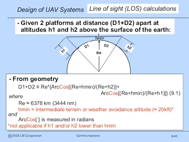
- Given 2 platforms at distance (D1+D2) apart at altitudes h1
- Given 2 platforms at distance (D1+D2) apart at altitudes h1
9-46
RF line of sight
Due to earth curvature and atmospheric index of
9-46
RF line of sight
Due to earth curvature and atmospheric index of
9-47
Grazing angle effects
Ignore the small differences between LOS and LOS’
9-47
Grazing angle effects
Ignore the small differences between LOS and LOS’
9-48
Airborne relay
A system level solution for an organic over the horizon
9-48
Airborne relay
A system level solution for an organic over the horizon
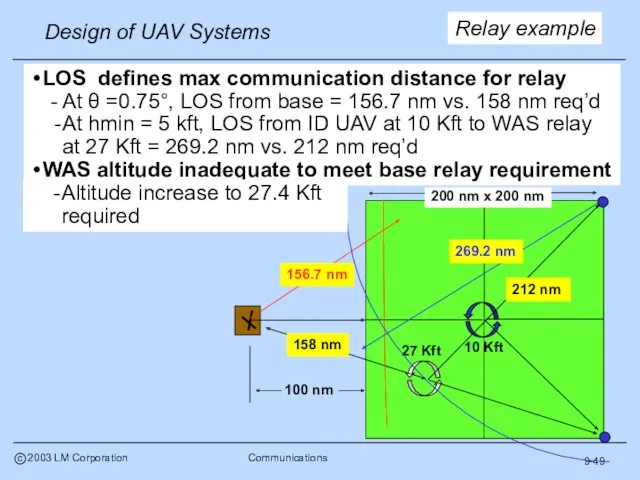
9-49
LOS defines max communication distance for relay
- At θ =0.75°,
9-49
LOS defines max communication distance for relay
- At θ =0.75°,
9-50
There is little public information available on UAV data links to
9-50
There is little public information available on UAV data links to
9-51
ADT range and power
Calculate LOS range
Equations 9.1-9.4
Estimate RF output power required
9-51
ADT range and power
Calculate LOS range
Equations 9.1-9.4
Estimate RF output power required
9-52
Initial sizing - ADT Satcom
Parametric correlation basis
Known correlation between band width
9-52
Initial sizing - ADT Satcom
Parametric correlation basis
Known correlation between band width
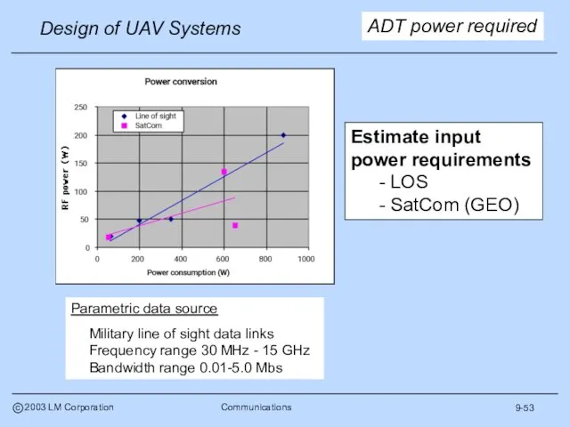
9-53
ADT power required
Parametric data source
Military line of sight data links
Frequency
9-53
ADT power required
Parametric data source
Military line of sight data links
Frequency
9-54
ADT weight
Parametric data source
Janes and unpublished data
Frequency range 30 MHz
9-54
ADT weight
Parametric data source
Janes and unpublished data
Frequency range 30 MHz
9-55
ADT volume
Parametric data source
All LOS data links & modems
Frequency range
9-55
ADT volume
Parametric data source
All LOS data links & modems
Frequency range
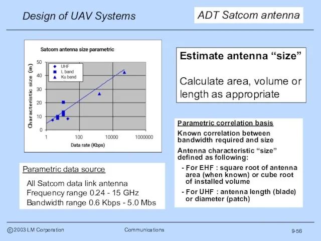
Parametric correlation basis
Known correlation between bandwidth required and size
Antenna characteristic
Parametric correlation basis
Known correlation between bandwidth required and size
Antenna characteristic
9-57
ADT satcom antenna
Parametric data source
All Satcom data link antenna
Frequency range
9-57
ADT satcom antenna
Parametric data source
All Satcom data link antenna
Frequency range
9-58
More ADT LOS data
Median = .025
Median = .045
Parametric data
9-58
More ADT LOS data
Median = .025
Median = .045
Parametric data
9-59
All systems on an air vehicle have an installation weight and
9-59
All systems on an air vehicle have an installation weight and
9-60
GDT options
There are a few GDT system descriptions in Janes and
9-60
GDT options
There are a few GDT system descriptions in Janes and
9-61
GDT parametrics
9-61
GDT parametrics
9-62
Expectations
You should understand
Communications fundamentals
UAV unique communications issues
How to calculate communication
9-62
Expectations
You should understand
Communications fundamentals
UAV unique communications issues
How to calculate communication
9-63
Final subject
RF basics
Data link types
Frequency bands
Antennae
Equations
Communications issues
Architecture
Function
Coverage
Etc.
Sizing (air and ground)
Range
Weight
Volume
Power
Example
9-63
Final subject
RF basics
Data link types
Frequency bands
Antennae
Equations
Communications issues
Architecture
Function
Coverage
Etc.
Sizing (air and ground)
Range
Weight
Volume
Power
Example
9-64
Example problem
Five medium UAVs, four provide wide area search, a fifth
9-64
Example problem
Five medium UAVs, four provide wide area search, a fifth
9-65
Parametric data is used to size (1) a basic UAV data
9-65
Parametric data is used to size (1) a basic UAV data
9-66
We have little GDT parametric sizing date and simply assume an
9-66
We have little GDT parametric sizing date and simply assume an
9-67
Requirements update
System element
GDT weight/volume/power excluding antenna (each)
= 205 lbm/9.5
9-67
Requirements update
System element
GDT weight/volume/power excluding antenna (each)
= 205 lbm/9.5
9-68
Homework
Assess communication requirements for your project and develop an architecture that
9-68
Homework
Assess communication requirements for your project and develop an architecture that
 Terrorism and counterterrorism. 5 assumptions on terrorism
 Complex object (v + object + (to) infinitive). Сложное дополнение
 Созылыңқы өткен шақ
 There is, there are. Choose the right option
 Job hunting
 London. Great Britain
 Prepositions of place. Предлоги места
 Hobbies and interests
 Healthy food
 There is/There are. Грамматический практикум
 Winners of the contest “My city is my Moscow”
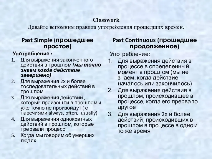 Правила употребления прошедших времен. Past Simple
 Who wants to be a millionaire?
 Independent work. Fractures
 Сравнительно-типологическое описание синтаксических систем английского и русского языков. Лекция 4
 How to Identify a Shopaholic?
 Bilingual education in Australia
 There is. There are
 Mathematical Induction
 Методика навчання іноземних мов і перекладу
 Food
Food This is my house 3
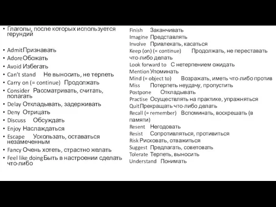 Глаголы, после которых используется герундий. Инфинитив
 Commonwealth of Australia
 Teaching listening
 Hippie
 Числительные в функции обстоятельства времени
 Прилагательные и наречия