- Line differential protection 7SD52x / 7SD610. Siemens

Содержание
- 2. Line differential relays 87L- SIPROTEC 4 Universal Line Differential Relays 87L - 7SD610 (2 ends) 7SD522
- 3. Customer Benefits The protection adapts its characteristic by itself. Adaptive measurement reduces the setting complexity and
- 4. Hardware options 7SD610 1/3 19’’ (3 / 1)* 3 / 1 7 5 1 4 Lines
- 5. Protection and communication join together Three benefits of 87L-SIPROTEC
- 6. Main protection function 87: Features of the differential function
- 7. Additional functions in the relay
- 8. Communication features
- 9. IDiff>: Vector comparison
- 10. IDiff>: Vector comparison with Advanced Fourier filters (Basic principle) Complex vector I = 2/N ( IC
- 11. IDiff>: Theory of the classical differential tripping characteristic
- 12. Example: CT class 10P10, Sn = 10VA , Isn= 1A 10% tolerance at KSSC (= 10
- 13. IDiff>: Settings for the “CT – parameters” (2 of 2)
- 14. IDiff>: Approximation of the CT- error
- 15. IDiff>: Example for a setting at nominal current
- 16. IDiff>: Adaptive differential relaying Restraint current with consideration of the CT- errors
- 17. IDiff>: New differential method compared with a classical differential characteristic
- 18. 5P20, 20 VA 1600/1A kALF/ kALF_N = 5 **) εLoad = 3% (0.03) εFault = 10%
- 19. IDiff>: CT- saturation detector based on harmonic analysis of the current wave form - Signal analysis
- 20. Trip, if differential current exceeds the estimated error (= increased restraint) IDiff = │I1+ I2│ IError
- 21. IDiff>: Test: max. asymmetrical offset , Ct saturation
- 22. IDiff>: Adaptive consideration of a permanent time difference in transmit- and receive direction (For more details:
- 23. IDiff>: Adaptive consideration of a permanent time difference. Total “Restraint Current” Diff. current:: IDiff = IC
- 24. IDiff>: Sliding data windows after fault inception
- 25. IDiff>> (QDiff) : Fast current comparison
- 26. IDiff>> (QDiff) : Fast current comparison algorithm (Basic principle) Q2 Corrected time instants after end-to-end time
- 27. CT- requirements, mismatch of the primary CT currents
- 28. Application - Transformer and line/cable in the protection zone 20 MVA, 110 kV/20 kV, YNd1 10P10,
- 29. Examples for different Topologies
- 30. Relay to Relay Communication Designed for the use of Digital Communication Networks and FO 1) Main
- 31. Relay to Relay Communication (Overview) side 1 side 2 or 7SD52x / 610 or or 7SD52x
- 32. Relay to Relay Communication - Communication modules, Protection Interface (PI) Options for the Protection Interface Plug
- 33. Relay to Relay Communication - Communication converter
- 34. Relay to Relay Communication - Application: Fibre optic connection Direct connection with fibre optic (FO) cables
- 35. Relay to Relay Communication - Application: Digital communication network E O Communication- system Communication converter 7XV5662-0AA00
- 36. Relay to Relay Communication - Application: ISDN network
- 37. Relay to Relay Communication - Application: Leased telephone line or Pilot wire (1 of 2)
- 38. Relay to Relay Communication - Application: Leased telephone line or Pilot wire (2 of 2)
- 39. Relay to Relay Communication - Application for a three terminal configuration with 7SD523
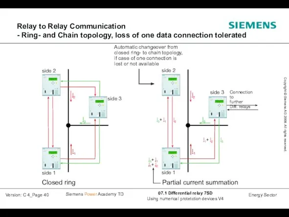
- 40. Relay to Relay Communication - Ring- and Chain topology, loss of one data connection tolerated
- 41. FO5 62.5/125 um side 2 I2 I1 Direct FO- connection. Main connection 512 kBit/s for the
- 42. Commissioning and operating aids (1 of 5)
- 43. Commissioning and operating aids (2 of 5)
- 44. Commissioning and operating aids (3 of 5)
- 45. Commissioning and operating aids (4 of 5)
- 47. Скачать презентацию
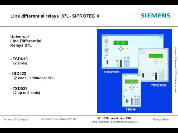
Line differential relays 87L- SIPROTEC 4
Universal
Line Differential
Relays 87L
- 7SD610
(2 ends)
Line differential relays 87L- SIPROTEC 4
Universal
Line Differential
Relays 87L
- 7SD610
(2 ends)
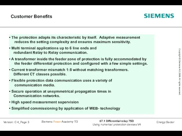
Customer Benefits
The protection adapts its characteristic by itself. Adaptive measurement
Customer Benefits
The protection adapts its characteristic by itself. Adaptive measurement
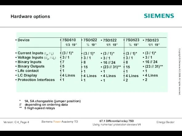
Hardware options
7SD610
1/3 19’’
(3 / 1)*
3 /
Hardware options
7SD610
1/3 19’’
(3 / 1)*
3 /
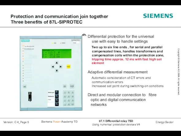
Protection and communication join together
Three benefits of 87L-SIPROTEC
Protection and communication join together
Three benefits of 87L-SIPROTEC
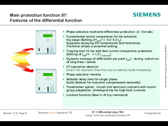
Main protection function 87:
Features of the differential function
Main protection function 87:
Features of the differential function
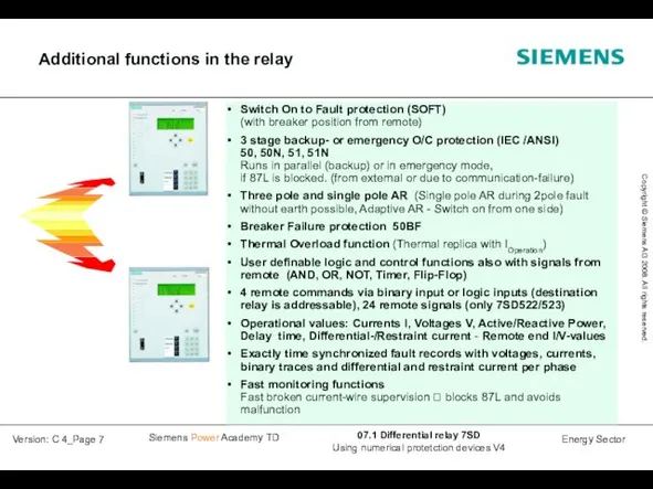
Additional functions in the relay
Additional functions in the relay
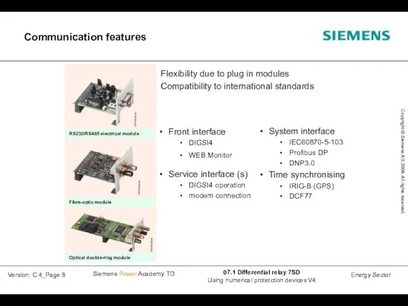
Communication features
Communication features
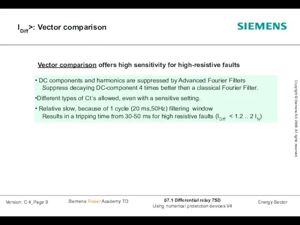
IDiff>: Vector comparison
IDiff>: Vector comparison
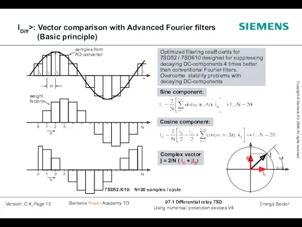
IDiff>: Vector comparison with Advanced Fourier filters
(Basic principle)
Complex vector
I =
IDiff>: Vector comparison with Advanced Fourier filters
(Basic principle)
Complex vector I =
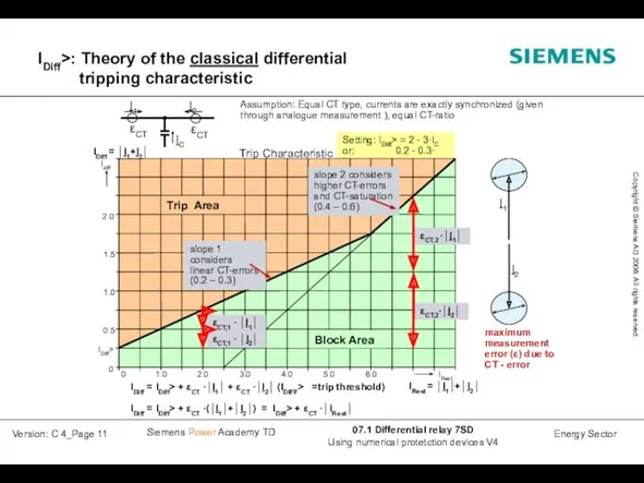
IDiff>: Theory of the classical differential tripping characteristic
IDiff>: Theory of the classical differential tripping characteristic
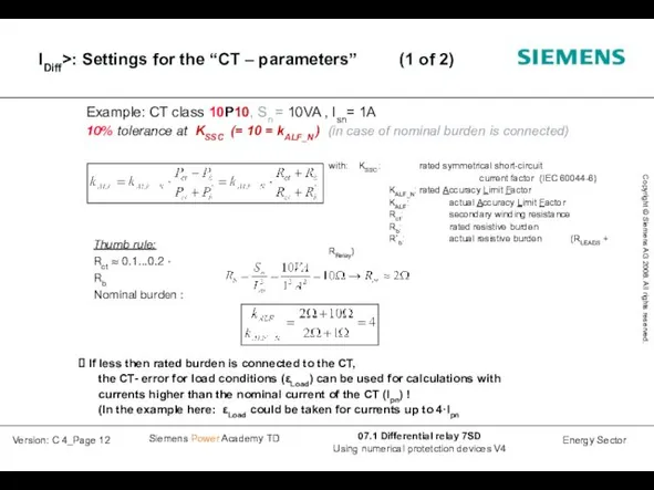
Example: CT class 10P10, Sn = 10VA , Isn= 1A
10% tolerance
Example: CT class 10P10, Sn = 10VA , Isn= 1A
10% tolerance
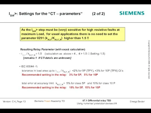
IDiff>: Settings for the “CT – parameters” (2 of 2)
IDiff>: Settings for the “CT – parameters” (2 of 2)
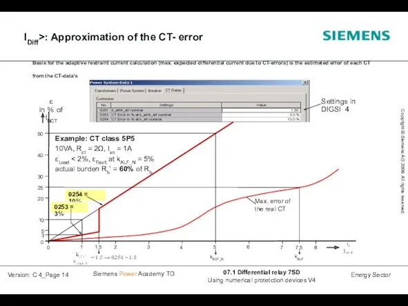
IDiff>: Approximation of the CT- error
IDiff>: Approximation of the CT- error
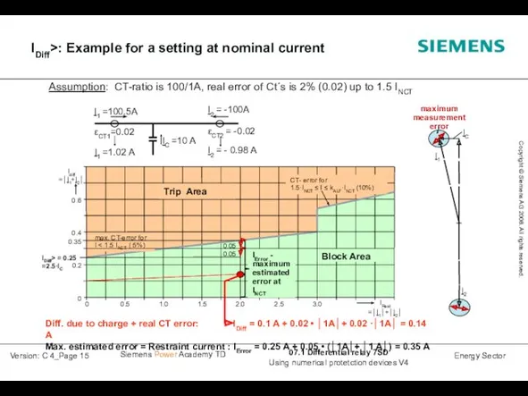
IDiff>: Example for a setting at nominal current
IDiff>: Example for a setting at nominal current

IDiff>: Adaptive differential relaying
Restraint current with consideration of the CT-
IDiff>: Adaptive differential relaying Restraint current with consideration of the CT-
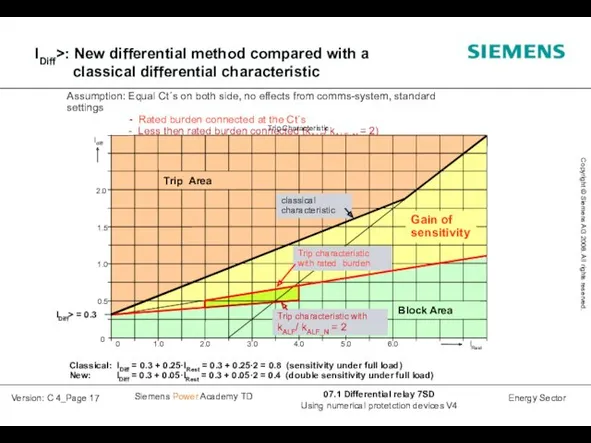
IDiff>: New differential method compared with a
classical differential characteristic
IDiff>: New differential method compared with a
classical differential characteristic
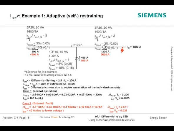
5P20, 20 VA
1600/1A
kALF/ kALF_N = 5 **)
εLoad = 3% (0.03)
εFault =
5P20, 20 VA
1600/1A
kALF/ kALF_N = 5 **)
εLoad = 3% (0.03)
εFault =

IDiff>: CT- saturation detector based on harmonic analysis
of the current
IDiff>: CT- saturation detector based on harmonic analysis of the current
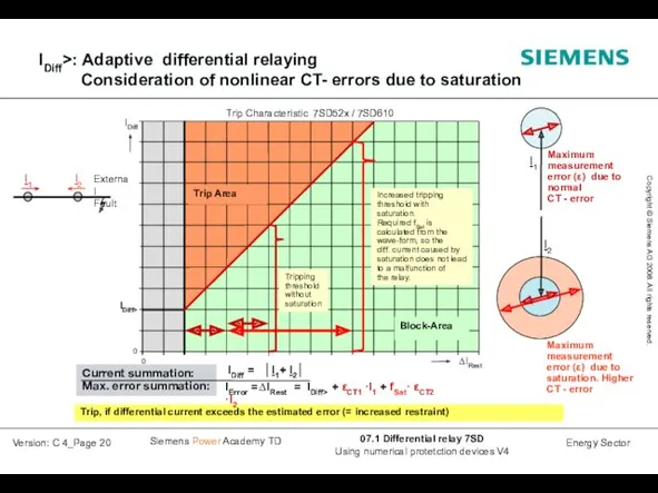
Trip, if differential current exceeds the estimated error (= increased restraint)
IDiff
Trip, if differential current exceeds the estimated error (= increased restraint)
IDiff
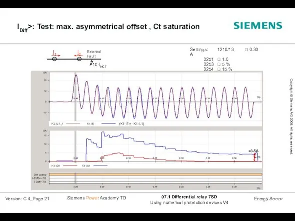
IDiff>: Test: max. asymmetrical offset , Ct saturation
IDiff>: Test: max. asymmetrical offset , Ct saturation
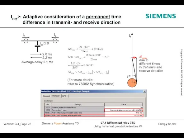
IDiff>: Adaptive consideration of a permanent time difference in transmit- and
IDiff>: Adaptive consideration of a permanent time difference in transmit- and
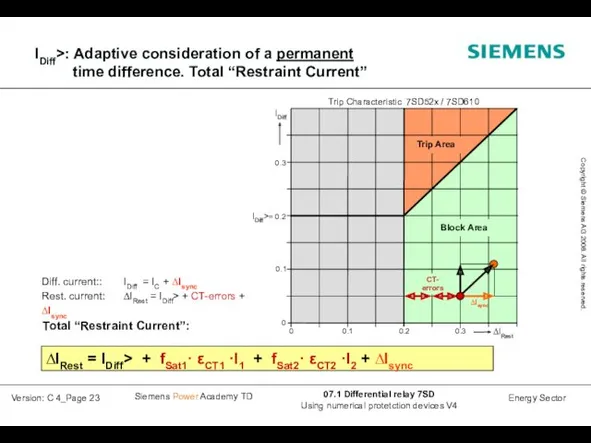
IDiff>: Adaptive consideration of a permanent time difference. Total “Restraint Current”
Diff.
IDiff>: Adaptive consideration of a permanent time difference. Total “Restraint Current”
Diff.
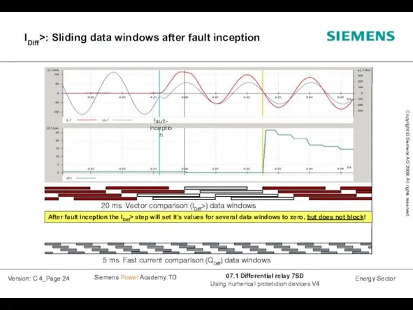
IDiff>: Sliding data windows after fault inception
IDiff>: Sliding data windows after fault inception
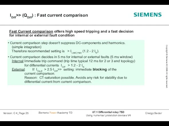
IDiff>> (QDiff) : Fast current comparison
IDiff>> (QDiff) : Fast current comparison
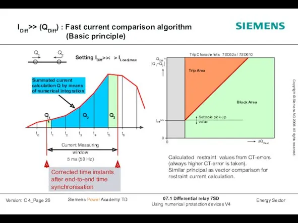
IDiff>> (QDiff) : Fast current comparison algorithm
(Basic principle)
Q2
Corrected time
IDiff>> (QDiff) : Fast current comparison algorithm
(Basic principle)
Q2
Corrected time
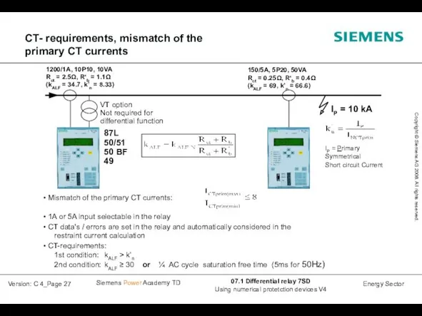
CT- requirements, mismatch of the
primary CT currents
CT- requirements, mismatch of the
primary CT currents
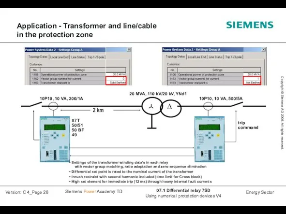
Application - Transformer and line/cable
in the protection zone
20 MVA, 110
Application - Transformer and line/cable
in the protection zone
20 MVA, 110
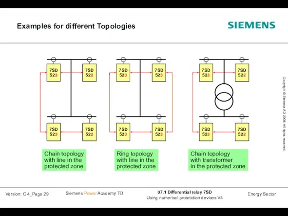
Examples for different Topologies
Examples for different Topologies
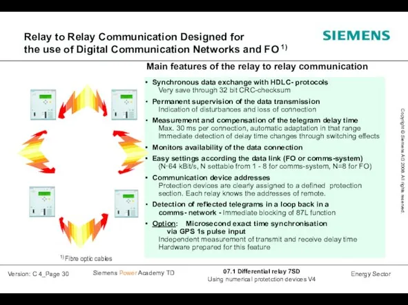
Relay to Relay Communication Designed for
the use of Digital Communication Networks
Relay to Relay Communication Designed for the use of Digital Communication Networks
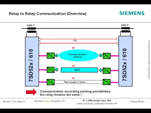
Relay to Relay Communication (Overview)
side 1
side 2
or
7SD52x / 610
or
or
7SD52x / 610
Relay to Relay Communication (Overview)
side 1
side 2
or
7SD52x / 610
or
or
7SD52x / 610
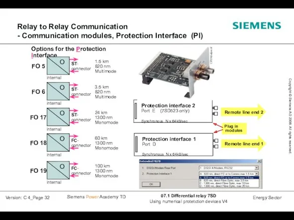
Relay to Relay Communication
- Communication modules, Protection Interface (PI)
Options for the
Relay to Relay Communication
- Communication modules, Protection Interface (PI)
Options for the
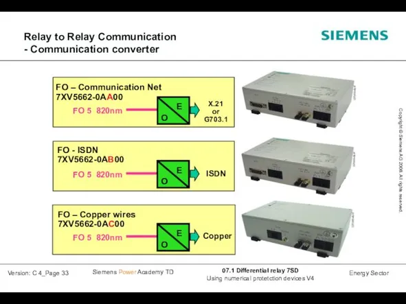
Relay to Relay Communication
- Communication converter
Relay to Relay Communication
- Communication converter
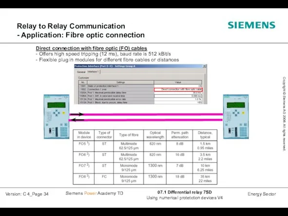
Relay to Relay Communication
- Application: Fibre optic connection
Direct connection with
Relay to Relay Communication
- Application: Fibre optic connection
Direct connection with
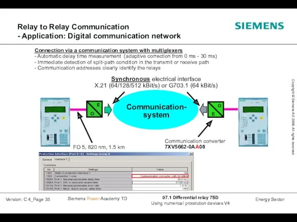
Relay to Relay Communication
- Application: Digital communication network
E
O
Communication-
system
Communication converter
7XV5662-0AA00
FO 5,
Relay to Relay Communication
- Application: Digital communication network
E
O
Communication-
system
Communication converter
7XV5662-0AA00
FO 5,
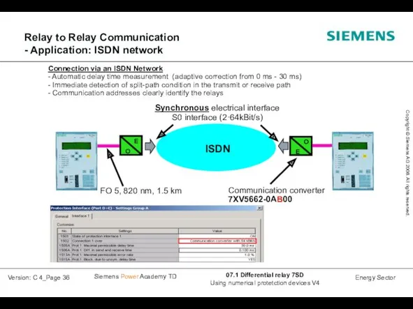
Relay to Relay Communication
- Application: ISDN network
Relay to Relay Communication
- Application: ISDN network
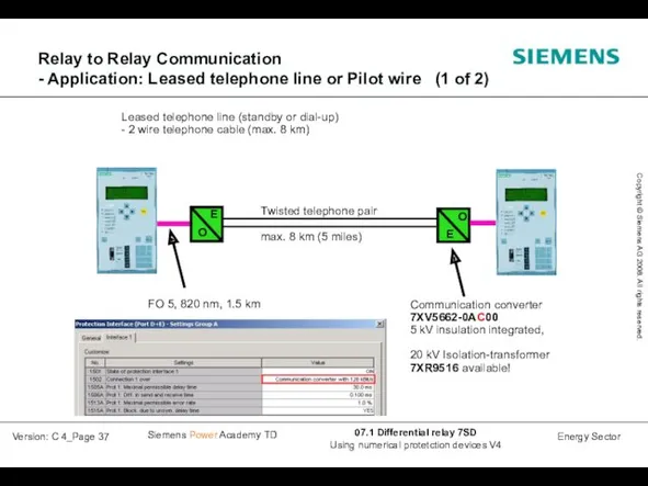
Relay to Relay Communication
- Application: Leased telephone line or Pilot
Relay to Relay Communication - Application: Leased telephone line or Pilot
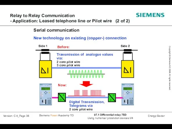
Relay to Relay Communication
- Application: Leased telephone line or Pilot
Relay to Relay Communication - Application: Leased telephone line or Pilot
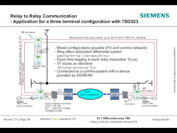
Relay to Relay Communication
- Application for a three terminal configuration
Relay to Relay Communication - Application for a three terminal configuration
Relay to Relay Communication
- Ring- and Chain topology, loss of
Relay to Relay Communication - Ring- and Chain topology, loss of
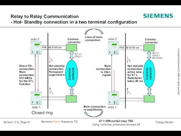
FO5 62.5/125 um
side 2
I2
I1
Direct FO-
connection.
Main
connection
512 kBit/s
for the 87L
function
Closed ring
side 1
Comms-
converter
Comms-
network
FO5 62.5/125 um
side 2
I2
I1
Direct FO-
connection.
Main
connection
512 kBit/s
for the 87L
function
Closed ring
side 1
Comms-
converter
Comms- network
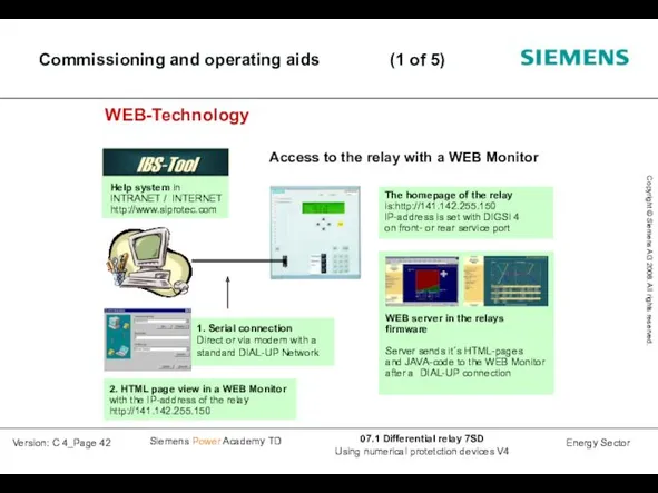
Commissioning and operating aids (1 of 5)
Commissioning and operating aids (1 of 5)
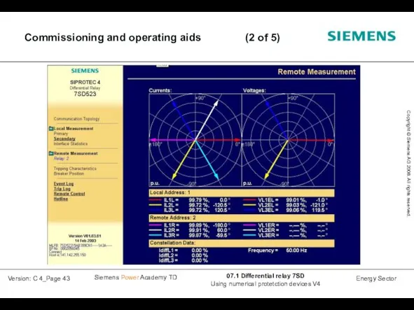
Commissioning and operating aids (2 of 5)
Commissioning and operating aids (2 of 5)
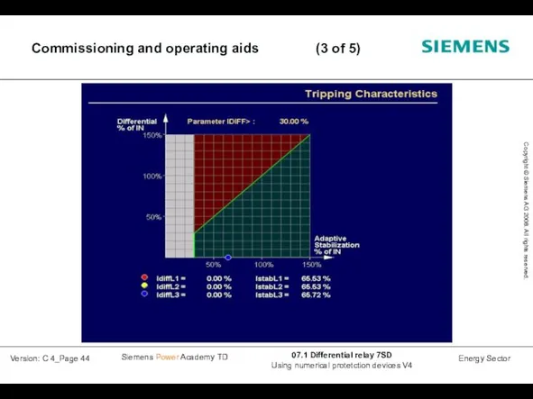
Commissioning and operating aids (3 of 5)
Commissioning and operating aids (3 of 5)
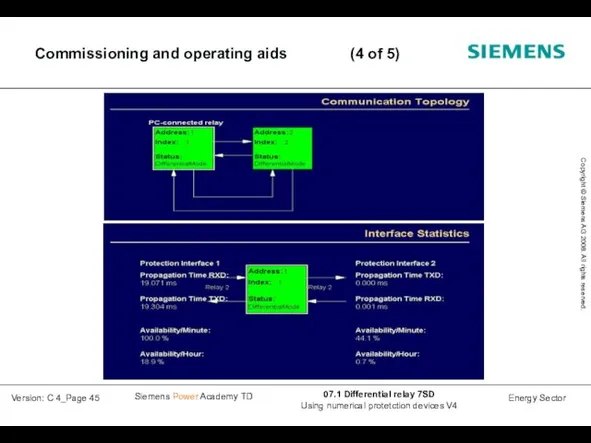
Commissioning and operating aids (4 of 5)
Commissioning and operating aids (4 of 5)
 Now I Know
 Leisure Activities. Vocabulary
 The Future Continuous Будущее длительное время
 My favourite artist
 Алфавит, фонетика
 Start speaking. Английский устный, вариант 14
 Ecologic problems
 Урок 4. Английский язык
 Discourse analysis of the concept of ethics of care in the works of N. Noddings and its application in English teaching
 Sports and Games
 The seaside adventure
 История английского языка
 St. Valentine’s Day the day of love
 Describe a monster eacher switcher
 London Attractions
 Слова – паразиты в английском языке
 Compounding, clipping and blending
 Great Patriotic War
 Top 3 best ukraine traditional foods
 Interesting facts
 Формирование коммуникативной компетенции на уроках иностранного языка
 Today we are going to talk about food
 ОГЭ 2023. Написание электронного письма
 Animals in pictures
 Some/ any
 Electronic instrument
 Match a line in A with a line in B
 My Diary