- Features that are available only in the Advanced version: 3D simulation

Содержание
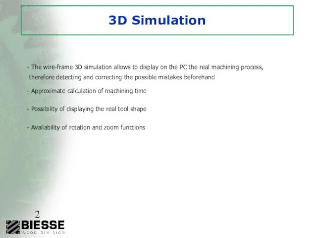
- 2. 3D Simulation The wire-frame 3D simulation allows to display on the PC the real machining process,
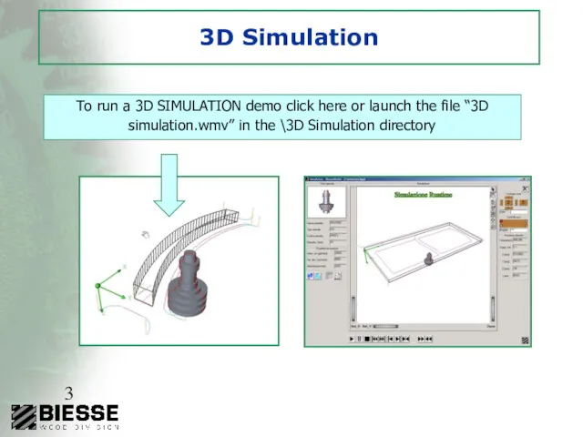
- 3. 3D Simulation To run a 3D SIMULATION demo click here or launch the file “3D simulation.wmv”
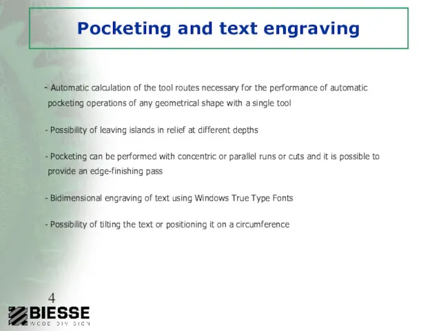
- 4. Pocketing and text engraving Automatic calculation of the tool routes necessary for the performance of automatic
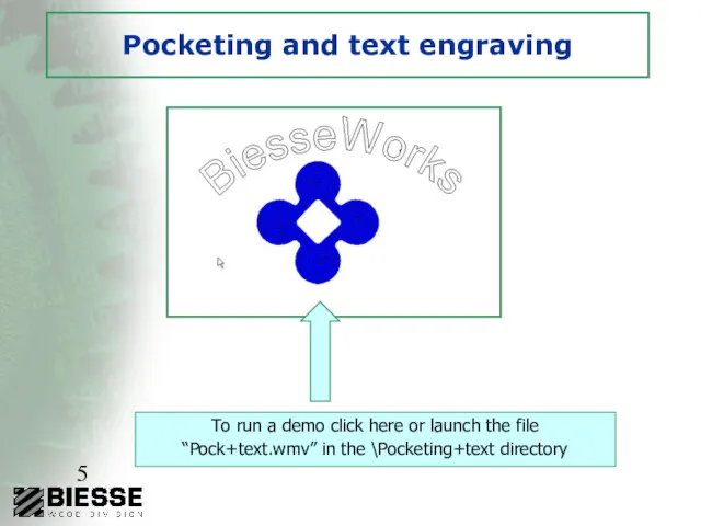
- 5. Pocketing and text engraving To run a demo click here or launch the file “Pock+text.wmv” in
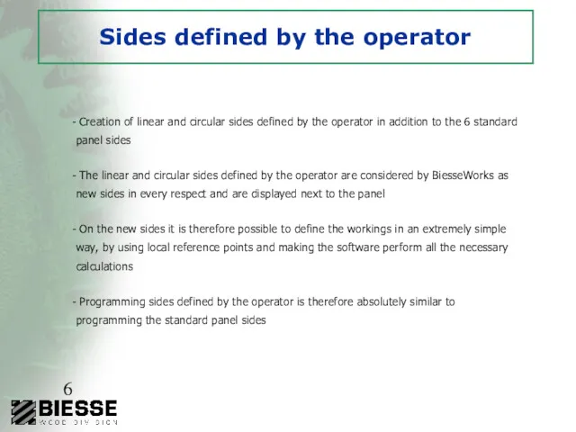
- 6. Sides defined by the operator Creation of linear and circular sides defined by the operator in
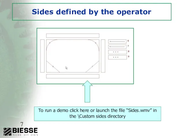
- 7. Sides defined by the operator To run a demo click here or launch the file “Sides.wmv”
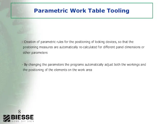
- 8. Parametric Work Table Tooling Creation of parametric rules for the positioning of locking devices, so that
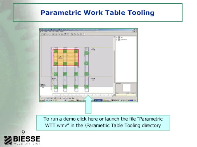
- 9. Parametric Work Table Tooling To run a demo click here or launch the file “Parametric WTT.wmv”
- 10. Chip deflector Chip deflector programming
- 11. Edge banding Easy and friendly programming for the edge banding and finishing process Tools for the
- 12. Edge banding
- 14. Скачать презентацию
3D Simulation
The wire-frame 3D simulation allows to display on the
3D Simulation
The wire-frame 3D simulation allows to display on the
3D Simulation
To run a 3D SIMULATION demo click here or launch
3D Simulation
To run a 3D SIMULATION demo click here or launch
Pocketing and text engraving
Automatic calculation of the tool routes necessary
Pocketing and text engraving
Automatic calculation of the tool routes necessary
Pocketing and text engraving
To run a demo click here or launch
Pocketing and text engraving
To run a demo click here or launch
Sides defined by the operator
Creation of linear and circular sides
Sides defined by the operator
Creation of linear and circular sides
Sides defined by the operator
To run a demo click here or
Sides defined by the operator
To run a demo click here or
Parametric Work Table Tooling
Creation of parametric rules for the
Parametric Work Table Tooling
Creation of parametric rules for the
Parametric Work Table Tooling
To run a demo click here or launch
Parametric Work Table Tooling
To run a demo click here or launch
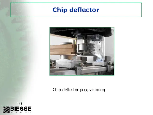
Chip deflector
Chip deflector programming
Chip deflector
Chip deflector programming
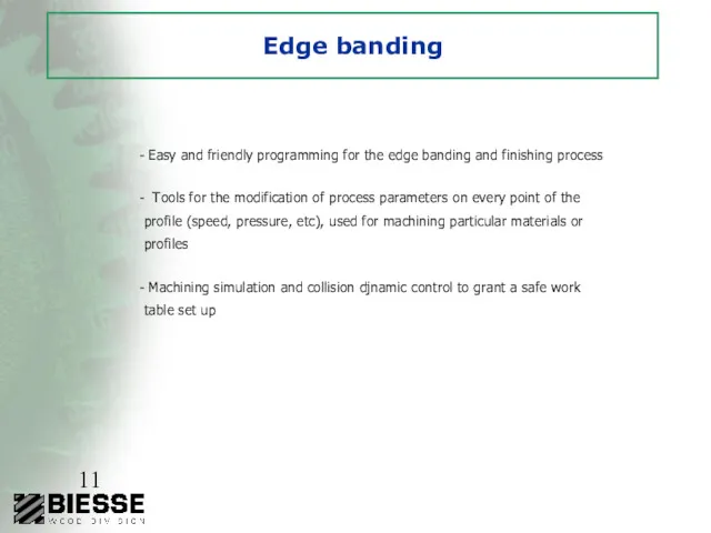
Edge banding
Easy and friendly programming for the edge banding and
Edge banding
Easy and friendly programming for the edge banding and
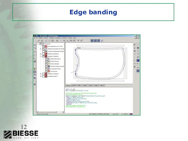
Edge banding
Edge banding
 Электронный информационный объект. Сборочный чертеж
 Шрифты в архитектурной графике
 Autodesk inventor файл-шаблон чертежа. Модуль поддержка ЕСКД. Базовый вид. Проекционный вид. Слои. Свойство ассоциативности
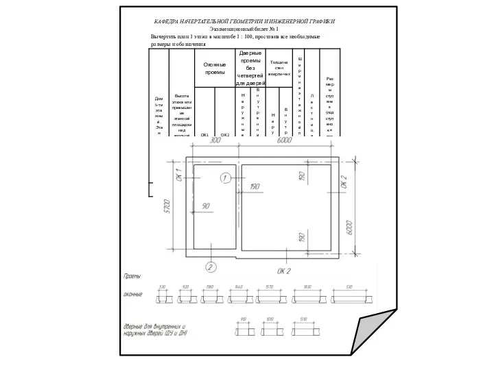 Подготовка к контрольной работе по начертательной геометрии
 Угловая перспектива
 Нарезание наружной и внутренней резьбы
 Зображення об’єктів на технічних креслениках. Види. Лекція 2
 Построение геометрических тел. Сопряжения
 Проекции плоскости (Лекция 3)
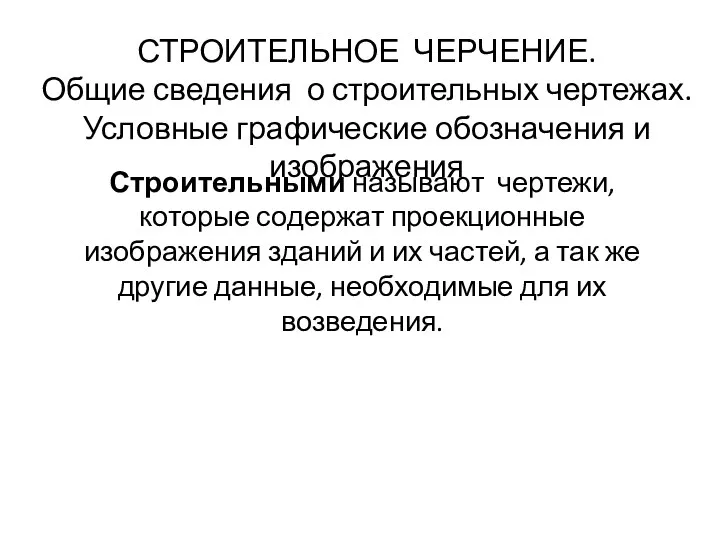 Строительное черчение. План этажа
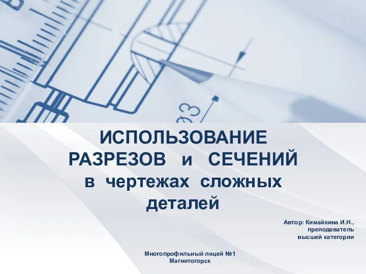 Разрезы и сеченя в чертежах сложных деталей
 Свойства ортогонального проецирования. Комплексный чертеж. (Лекция 1)
 Начертательная геометрия, инженерная и компьютерная графика. Курсовой проект
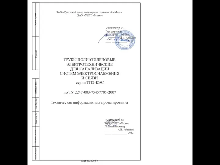 Труба для канализаций
 Desen tehnic. Dispunerea proiectiilor
 Резьба. Классификация резьбы. Изображение и обозначение резьбы на чертежах
 Загальні правила оформлення креслеників
 Соединения разъёмные
 Единая система конструкторской документации
 Фронтальная перспектива в архитектуре
 Фронтальная перспектива интерьера
 Рекомендации по выполнению контрольной работы по инженерной графике
 Резьбовые соединения
 МДК 01.01., 20.03.2021, ПР 1
 Дисциплина:Современное проектирование зданий и сооружений. Основные параметры
 Нарезание резьбы
 Линии чертежа
 ГОСТ 2.305-2008. Изображения на чертежах: виды, разрезы, сечения