- Sedimentation tank

Содержание
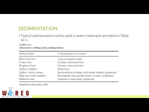
- 2. SEDIMENTATION Typical sedimentation tanks used in water treatment are listed in Table 10-1 .
- 3. preference for settling coagulation/flocculation floc is (1) a rectangular tank containing high-rate settler modules, (2) a
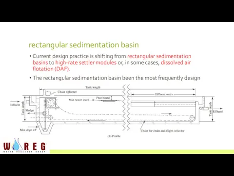
- 4. rectangular sedimentation basin Current design practice is shifting from rectangular sedimentation basins to high-rate settler modules
- 5. To provide redundancy, two basins are placed longitudinally with a common wall.
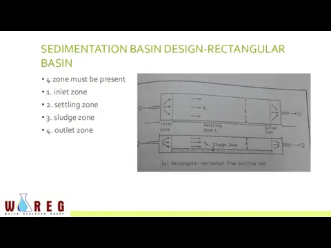
- 6. SEDIMENTATION BASIN DESIGN-RECTANGULAR BASIN 4 zone must be present 1. inlet zone 2. settling zone 3.
- 7. INLET ZONE preferred arrangement is a direct connection between the flocculation basin and the settling tank.
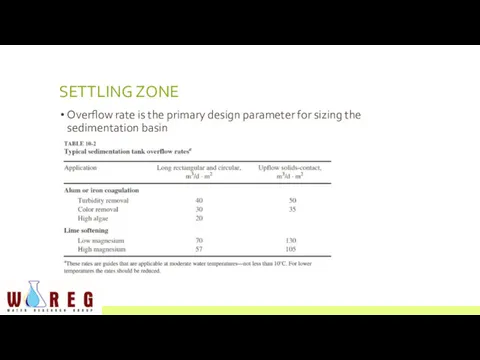
- 8. SETTLING ZONE Overflow rate is the primary design parameter for sizing the sedimentation basin
- 9. These rates are usually conservative enough that the inlet zone does not have to be added
- 10. The tank depth is usually increased by about 0.6 m to provide freeboard to act as
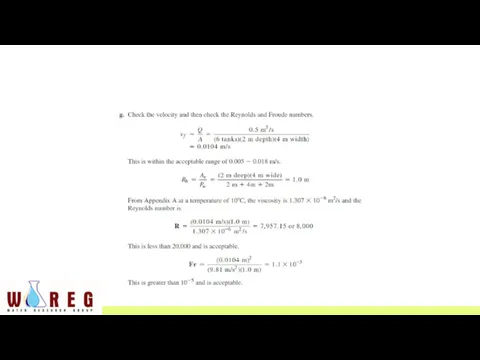
- 11. The Reynolds number is determined as:
- 12. The Froude number is determined as:
- 13. Recommended values for the settling zone design are R 10 -5 large Reynolds number indicates a
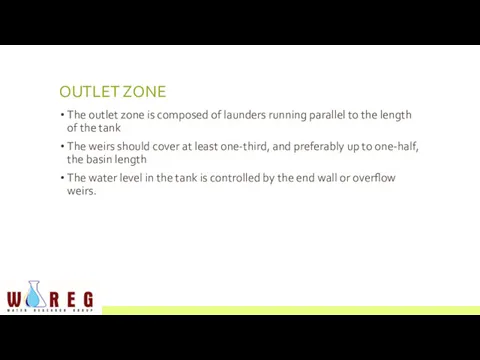
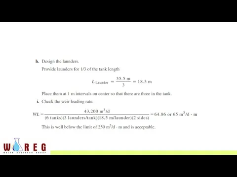
- 14. OUTLET ZONE The outlet zone is composed of launders running parallel to the length of the
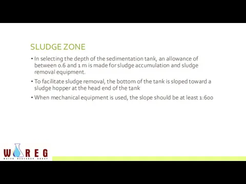
- 15. SLUDGE ZONE In selecting the depth of the sedimentation tank, an allowance of between 0.6 and
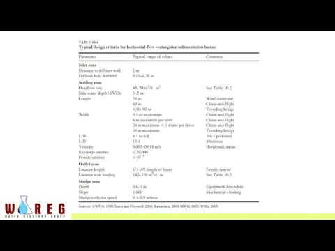
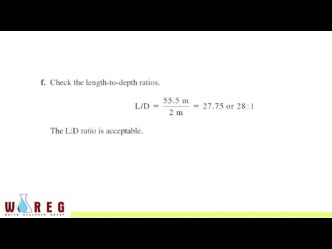
- 16. Typical design criteria for horizontal-flow rectangular sedimentation basins in larger water treatment plants (40,000 m3 /d)
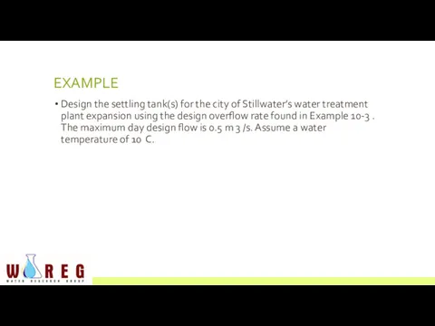
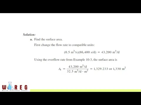
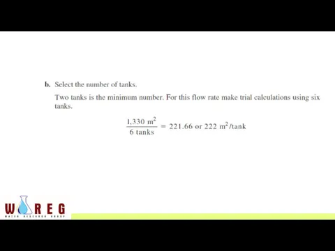
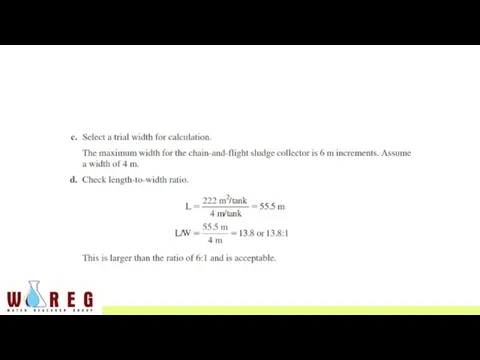
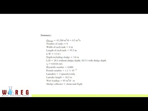
- 18. EXAMPLE Design the settling tank(s) for the city of Stillwater’s water treatment plant expansion using the
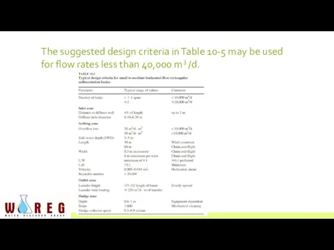
- 27. The suggested design criteria in Table 10-5 may be used for flow rates less than 40,000
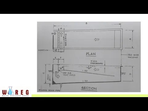
- 28. “LOVO TANK” Modification of rectangular horizontal flow sedimentation tank Incorporating an intermediate slanting slab spanning the
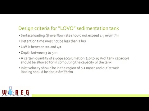
- 30. Design criteria for “LOVO” sedimentation tank Surface loading @ overflow rate should not exceed 1.5 m3/m2/hr
- 32. Скачать презентацию
SEDIMENTATION
Typical sedimentation tanks used in water treatment are listed in Table
SEDIMENTATION
Typical sedimentation tanks used in water treatment are listed in Table
preference for settling coagulation/flocculation floc is
(1) a rectangular tank containing
preference for settling coagulation/flocculation floc is
(1) a rectangular tank containing
rectangular sedimentation basin
Current design practice is shifting from rectangular sedimentation basins
rectangular sedimentation basin
Current design practice is shifting from rectangular sedimentation basins
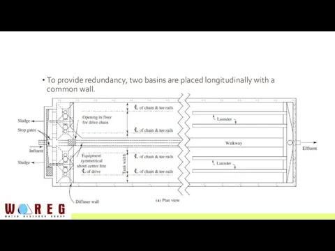
To provide redundancy, two basins are placed longitudinally with a common
To provide redundancy, two basins are placed longitudinally with a common
SEDIMENTATION BASIN DESIGN-RECTANGULAR BASIN
4 zone must be present
1. inlet zone
2. settling
SEDIMENTATION BASIN DESIGN-RECTANGULAR BASIN
4 zone must be present
1. inlet zone
2. settling
INLET ZONE
preferred arrangement is a direct connection between the flocculation basin
INLET ZONE
preferred arrangement is a direct connection between the flocculation basin
SETTLING ZONE
Overflow rate is the primary design parameter for sizing the
SETTLING ZONE
Overflow rate is the primary design parameter for sizing the
These rates are usually conservative enough that the inlet zone does
These rates are usually conservative enough that the inlet zone does
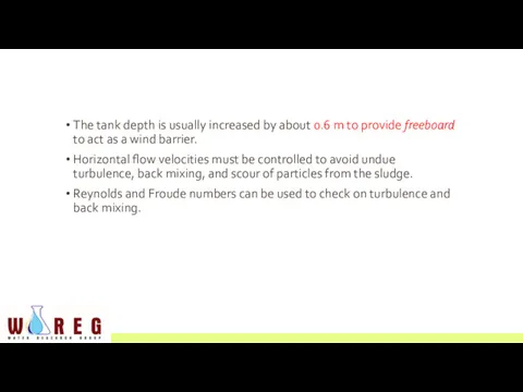
The tank depth is usually increased by about 0.6 m to
The tank depth is usually increased by about 0.6 m to
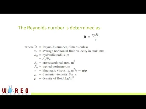
The Reynolds number is determined as:
The Reynolds number is determined as:
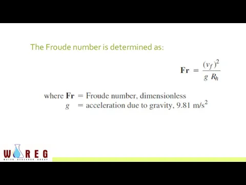
The Froude number is determined as:
The Froude number is determined as:
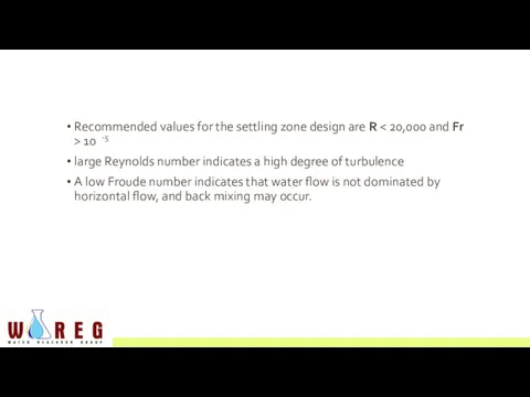
Recommended values for the settling zone design are R < 20,000
Recommended values for the settling zone design are R < 20,000
OUTLET ZONE
The outlet zone is composed of launders running parallel to
OUTLET ZONE
The outlet zone is composed of launders running parallel to
SLUDGE ZONE
In selecting the depth of the sedimentation tank, an allowance
SLUDGE ZONE
In selecting the depth of the sedimentation tank, an allowance
Typical design criteria for horizontal-flow rectangular sedimentation basins in larger water
Typical design criteria for horizontal-flow rectangular sedimentation basins in larger water
EXAMPLE
Design the settling tank(s) for the city of Stillwater’s water treatment
EXAMPLE
Design the settling tank(s) for the city of Stillwater’s water treatment

The suggested design criteria in Table 10-5 may be used
for flow
The suggested design criteria in Table 10-5 may be used for flow
“LOVO TANK”
Modification of rectangular horizontal flow sedimentation tank
Incorporating an intermediate slanting
“LOVO TANK”
Modification of rectangular horizontal flow sedimentation tank
Incorporating an intermediate slanting
Design criteria for “LOVO” sedimentation tank
Surface loading @ overflow rate should
Design criteria for “LOVO” sedimentation tank
Surface loading @ overflow rate should
 День Земли
 Глобальные проблемы
 Антропогенное воздействие на биосферу. Рост техносферы в XX веке
 Визитная карточка участников Межрегионального экологического проекта
 Қауіпті және зиянды факторларынын жіктелуі
 Группа 78 представляет: Наши мини-путешествия по Кирову в поисках чекпоинтов
 Загрязнение гидросферы
 Понятие биосферы и ноосферы
 Өнеркәсіп мекемелерінің қоршаған ортасын қорғау
 Современные проблемы охраны природы
 Цветочное оформление клумбы
 Экологическая демография
 Практичне значення лісів
 Всероссийский экологический квест ”Другая планета”
 Лесная викторина 2-3 класс. Вопросы об окружающей природе леса
 Polluter Pays Principle
 Қазіргі заманғы экологиялық мәселелер. Әртүрлі салалардағы ластанудың көздері мен сипаттамалары
 Эколята – Молодые защитники природы
 Особо охраняемые природные территории
 Экологические проблемы планеты Земля
 Повышение эффективности природоохранных мероприятий путем примененияметодов рекультивации загрязненных нефтью земель
 Автомобиль и окружающая среда
 Санитарно-гигиеническое значение атмосферного воздуха
 Всемирный День Земли. Судьба планеты Земля в наших руках
 Общество. Угрозы XXI века
 Урок по экологии
 Экологические проблемы обращения с особо опасными отходами и их решение
 Hygiene of water supply