- Fundamentals of Electrical Engineering

Содержание
- 2. INTRODUCTION So far covered: Ohm’s law and Kirchhoff’s laws This lecture covers powerful techniques for circuit
- 3. Nodal Analysis In nodal analysis, we are interested in finding the node voltages by applying KCL
- 4. Example Calculate the node voltages in the circuit shown The fact that i2 is negative shows
- 5. Problems Determine the voltages at the nodes
- 6. Problems Determine the voltages at the nodes
- 7. Nodal Analysis with Voltage Sources CASE 1: If a voltage source is connected between the reference
- 8. Example For the circuit shown find the node voltages.
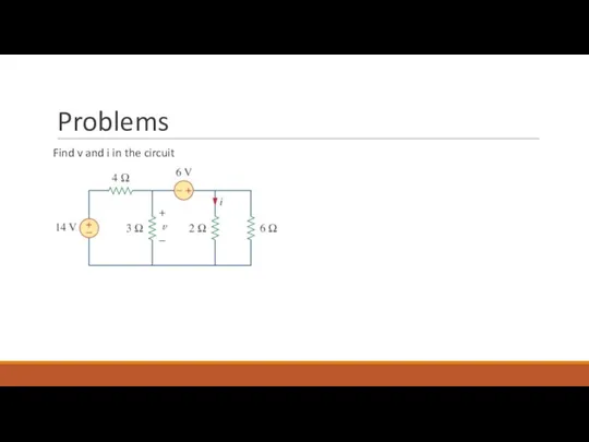
- 9. Problems Find v and i in the circuit
- 10. Problems Find v and i in the circuit V1 = 14 V 6 = V3 -
- 11. Mesh Analysis (Planar / Nonplanar) mesh analysis applies KVL to find mesh currents Mesh analysis is
- 12. Mesh Analysis A mesh (independent loop) is a loop which does not contain any other loops
- 13. Example For the circuit, find the branch currents using mesh analysis
- 14. Problem Use mesh analysis to find the current I0 in the circuit
- 15. Problem Use mesh analysis to find the current I0 in the circuit
- 17. Mesh Analysis with Current Sources the presence of the current sources reduces the number of equations
- 18. Example For the circuit, find i1 to i4 using mesh analysis i3 = i2 + 3*i4
- 19. Nodal and Mesh Analyses by Inspection (G1+G2)*v1 – G2*v2 = I1 – I2 (G2+G3)*v2 – G2*v1
- 20. Nodal Versus Mesh Analysis first factor is the nature of the particular network Networks that contain
- 22. Скачать презентацию
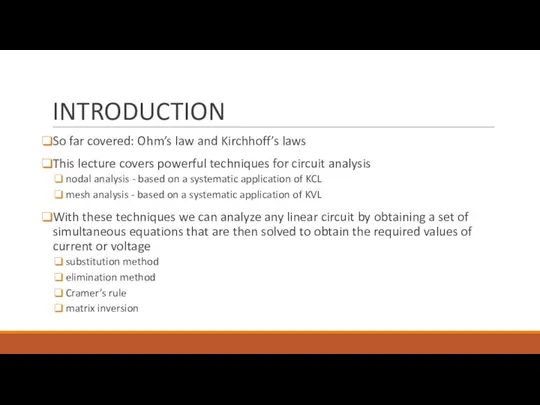
INTRODUCTION
So far covered: Ohm’s law and Kirchhoff’s laws
This lecture covers powerful
INTRODUCTION
So far covered: Ohm’s law and Kirchhoff’s laws
This lecture covers powerful
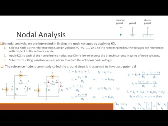
Nodal Analysis
In nodal analysis, we are interested in finding the node
Nodal Analysis
In nodal analysis, we are interested in finding the node
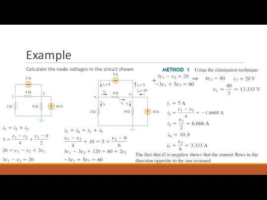
Example
Calculate the node voltages in the circuit shown
The fact that i2
Example
Calculate the node voltages in the circuit shown
The fact that i2

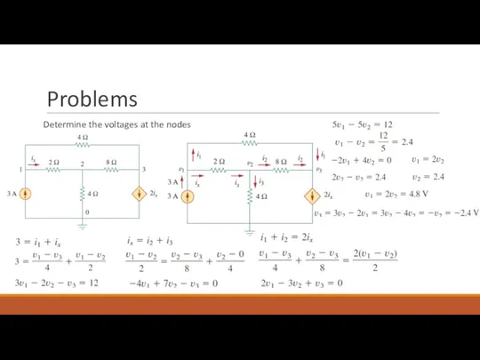
Problems
Determine the voltages at the nodes
Problems
Determine the voltages at the nodes
Problems
Determine the voltages at the nodes
Problems
Determine the voltages at the nodes

Nodal Analysis with Voltage Sources
CASE 1: If a voltage source is
Nodal Analysis with Voltage Sources
CASE 1: If a voltage source is
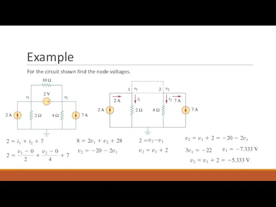
Example
For the circuit shown find the node voltages.
Example
For the circuit shown find the node voltages.
Problems
Find v and i in the circuit
Problems
Find v and i in the circuit

Problems
Find v and i in the circuit
V1 = 14 V
6 =
Problems
Find v and i in the circuit
V1 = 14 V
6 =
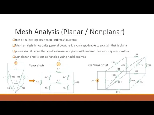
Mesh Analysis (Planar / Nonplanar)
mesh analysis applies KVL to find mesh
Mesh Analysis (Planar / Nonplanar)
mesh analysis applies KVL to find mesh
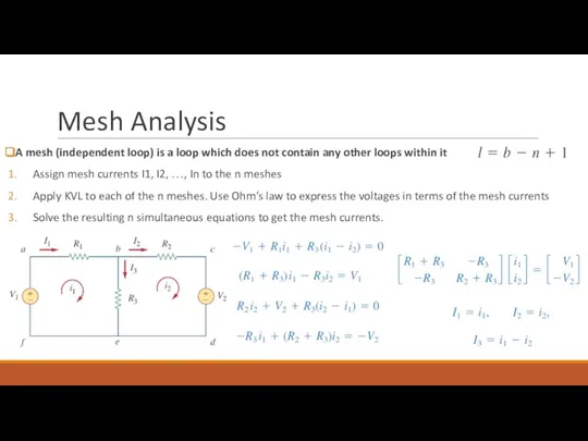
Mesh Analysis
A mesh (independent loop) is a loop which does not
Mesh Analysis
A mesh (independent loop) is a loop which does not
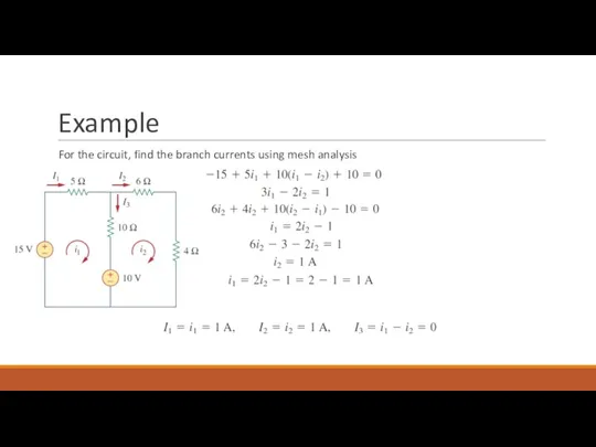
Example
For the circuit, find the branch currents using mesh analysis
Example
For the circuit, find the branch currents using mesh analysis
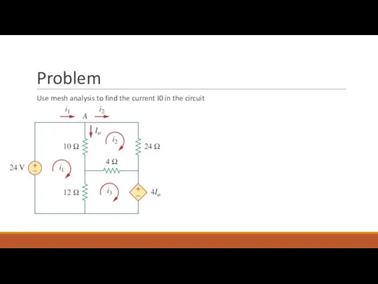
Problem
Use mesh analysis to find the current I0 in the circuit
Problem
Use mesh analysis to find the current I0 in the circuit
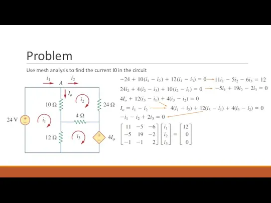
Problem
Use mesh analysis to find the current I0 in the circuit
Problem
Use mesh analysis to find the current I0 in the circuit

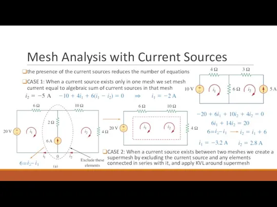
Mesh Analysis with Current Sources
the presence of the current sources reduces
Mesh Analysis with Current Sources
the presence of the current sources reduces
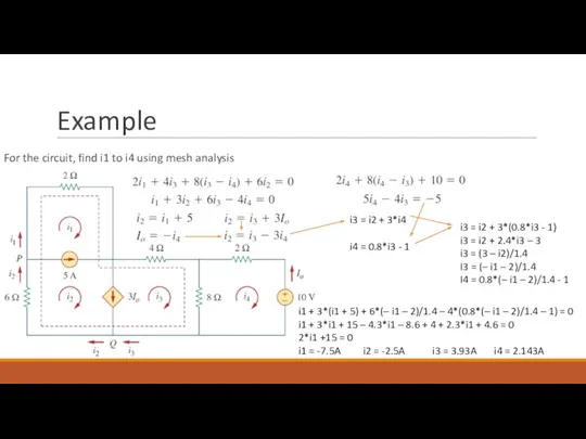
Example
For the circuit, find i1 to i4 using mesh analysis
i3 =
Example
For the circuit, find i1 to i4 using mesh analysis
i3 =
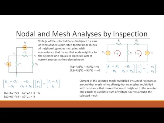
Nodal and Mesh Analyses by Inspection
(G1+G2)*v1 – G2*v2 = I1 –
Nodal and Mesh Analyses by Inspection
(G1+G2)*v1 – G2*v2 = I1 –

Nodal Versus Mesh Analysis
first factor is the nature of the particular
Nodal Versus Mesh Analysis
first factor is the nature of the particular
 Електростатичне поле
 Цепные передачи
 Қатты дененің механикасы
 Основы сопротивления материалов и физики прочности с использованием информационных технологий
 Акустика и акустическое оборудование
 Физика и техника
 Конструкция автомобиля
 Колебания и волны
 Технология RFID
 Свойства топлив. Теплота сгорания топлив. Урок № 4
 Класифікація лісогосподарських машин. Лекція №2
 Технология ТО и ремонта. Трансмиссия
 Урок - презентация - Обобщающее повторение по теме: Тепловые явления.
 Электрическая лампа накаливания. (6 класс)
 Значение радиоволн для физики и человечества. 11 класс
 Эвольвентное зацепление
 Магнитное поле. Взаимодействие токов
 Выбор конструкции и места соединения роторов ОК и ГТ
 Интерференция.
 Расчет градиентного ветра для широты Курска
 Специальные методы микроскопии
 20181129_elektricheskoe_soprotivlenie.udelnoe_soprotivlenie
 Влияние различных факторов на электропроводность овощей и фруктов
 Применение метода кислотно-основного титрования в количественном анализе химических веществ и лекарственных средств. (Лекция 7)
 Тепловое действие электрического тока: закон Джоуля-Ленца
 Energy and power, solar astronomy. (Lecture 4)
 Каучук. Резеңке. Шыны.Өнеркәсіптік шыны
 Основы теории передачи теплоты. Основные понятия и определения, механизмы переноса тепла. Теплопроводность