- Internal сombustion engine. Ignition systems

Содержание
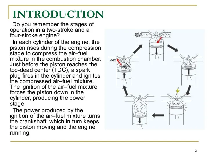
- 2. INTRODUCTION Do you remember the stages of operation in a two-stroke and a four-stroke engine? In
- 3. One of the requirements for an efficient engine is the correct amount of heat, delivered at
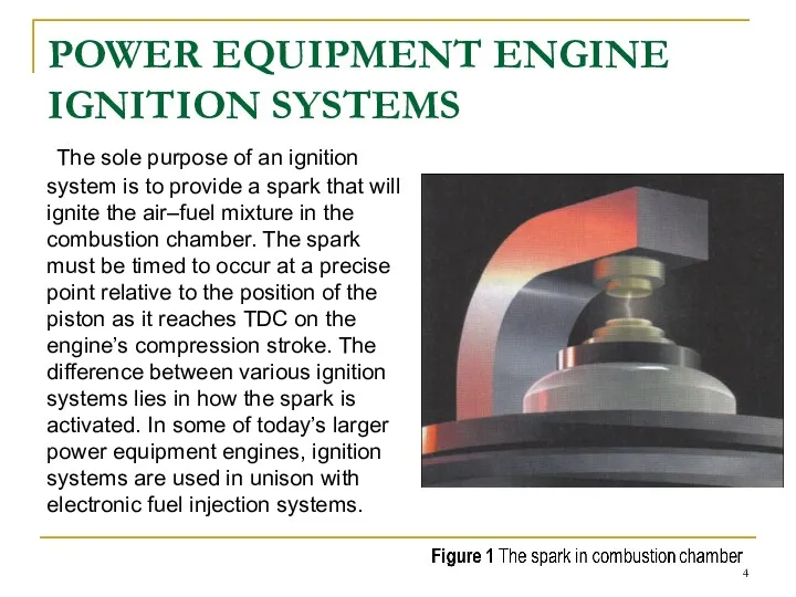
- 4. POWER EQUIPMENT ENGINE IGNITION SYSTEMS The sole purpose of an ignition system is to provide a
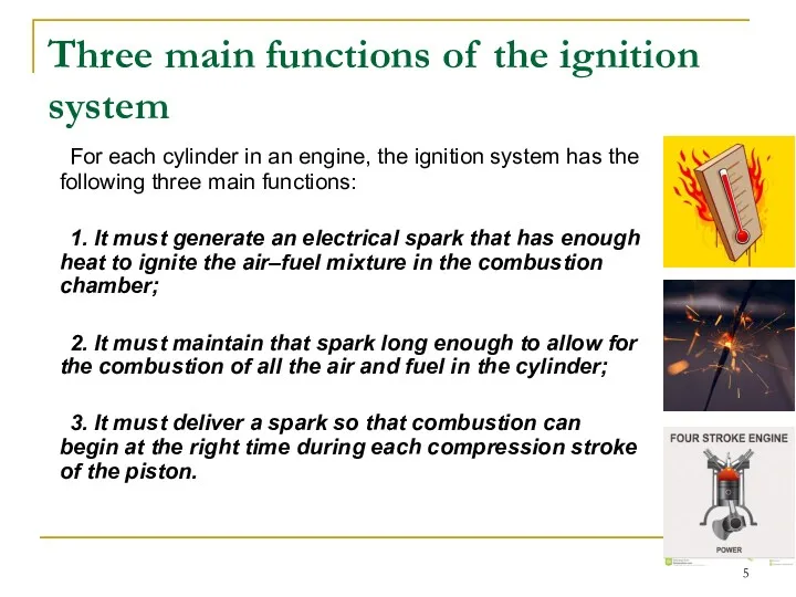
- 5. Three main functions of the ignition system For each cylinder in an engine, the ignition system
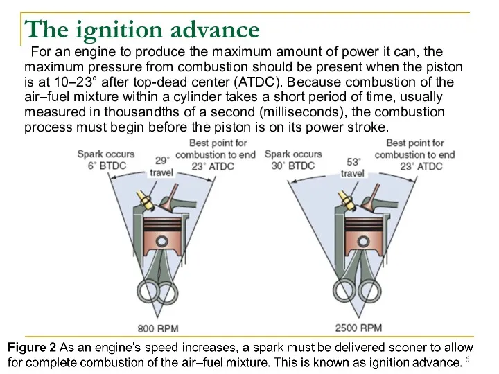
- 6. For an engine to produce the maximum amount of power it can, the maximum pressure from
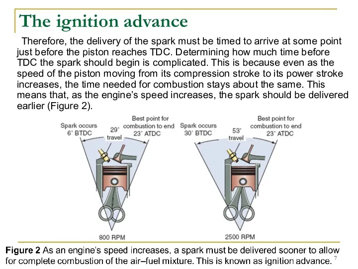
- 7. Therefore, the delivery of the spark must be timed to arrive at some point just before
- 8. Figure 2 As an engine’s speed increases, a spark must be delivered sooner to allow for
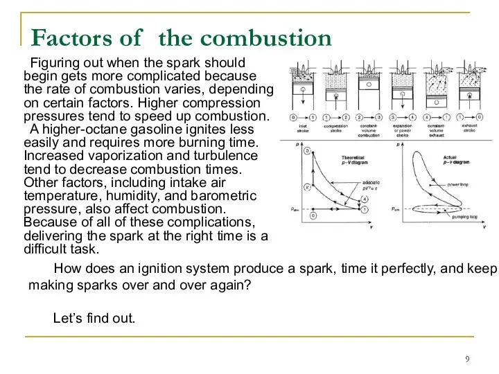
- 9. Figuring out when the spark should begin gets more complicated because the rate of combustion varies,
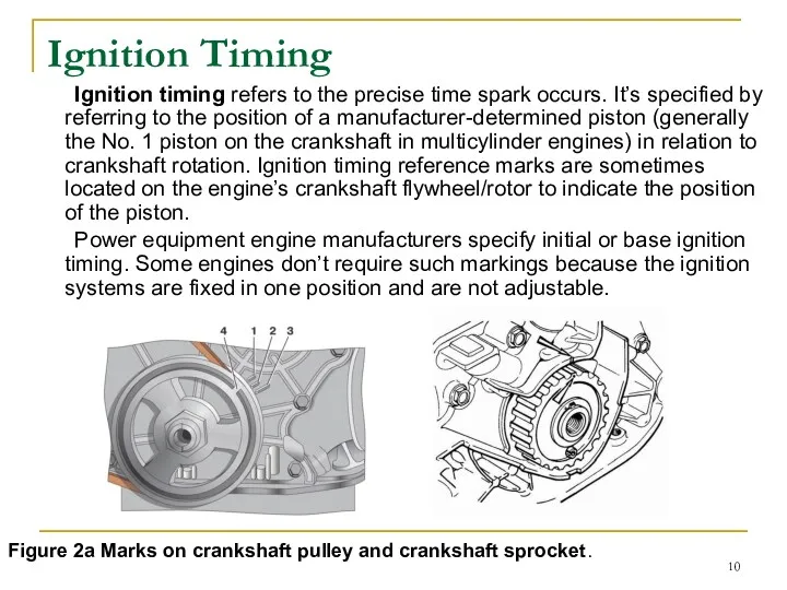
- 10. Ignition Timing Ignition timing refers to the precise time spark occurs. It’s specified by referring to
- 11. When the marks are aligned at TDC, the piston is at the TDC of the engine’s
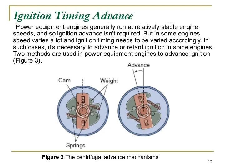
- 12. Ignition Timing Advance Power equipment engines generally run at relatively stable engine speeds, and so ignition
- 13. Ignition systems in older power equipment engines that require ignition timing advance are equipped with centrifugal
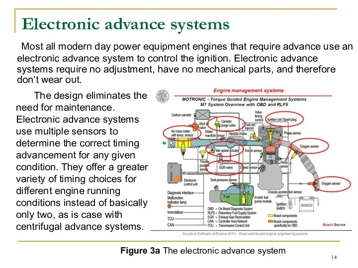
- 14. Electronic advance systems Most all modern day power equipment engines that require advance use an electronic
- 15. Engine rpm and Turbulence At higher rpm, the crankshaft turns through more degrees in a given
- 16. Engine Load The load on an engine is related to the work it must do. For
- 17. Firing Order in Multi-Cylinder Engines Up to this point, we’ve focused primarily on ignition timing as
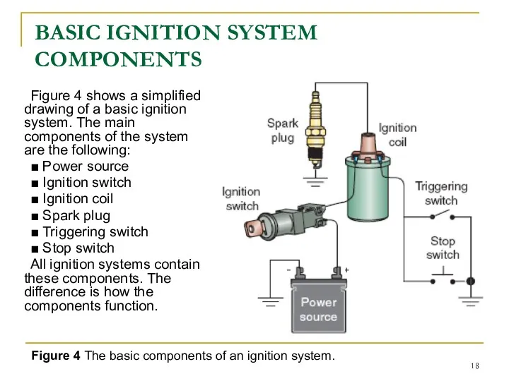
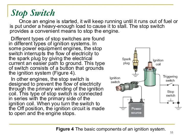
- 18. BASIC IGNITION SYSTEM COMPONENTS Figure 4 shows a simplified drawing of a basic ignition system. The
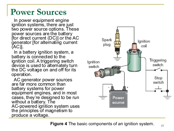
- 19. Power Sources In power equipment engine ignition systems, there are just two power source options. These
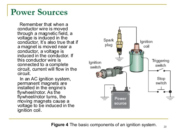
- 20. Power Sources Remember that when a conductor wire is moved through a magnetic field, a voltage
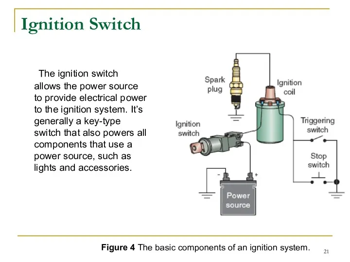
- 21. Ignition Switch The ignition switch allows the power source to provide electrical power to the ignition
- 22. Ignition Coil An ignition coil is essentially a transformer that consists of two wire windings wound
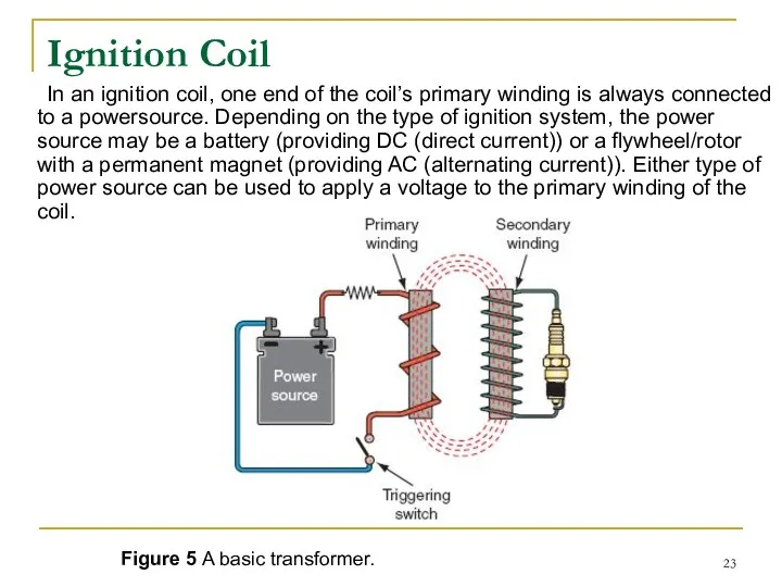
- 23. Ignition Coil In an ignition coil, one end of the coil’s primary winding is always connected
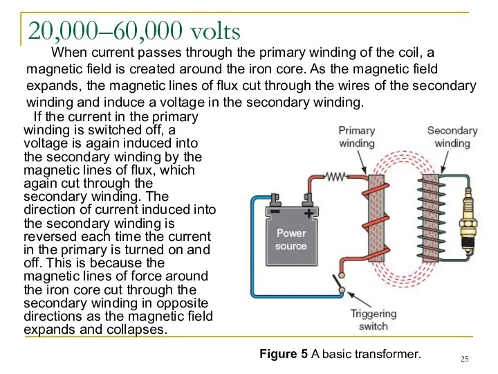
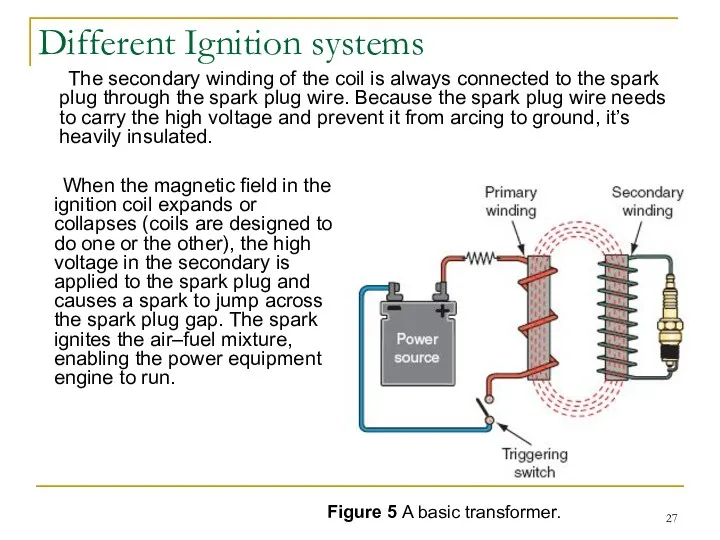
- 24. Figure 5 A basic transformer. When a voltage is applied to the primary winding, a voltage
- 25. 20,000–60,000 volts If the current in the primary winding is switched off, a voltage is again
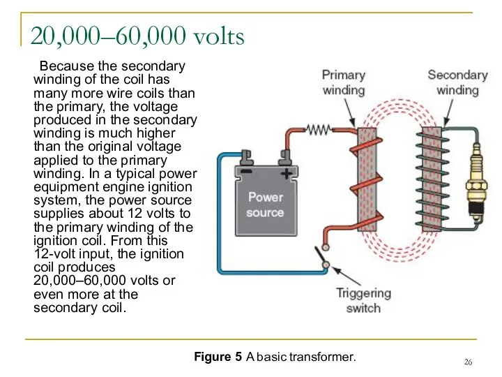
- 26. 20,000–60,000 volts Because the secondary winding of the coil has many more wire coils than the
- 27. Different Ignition systems The secondary winding of the coil is always connected to the spark plug
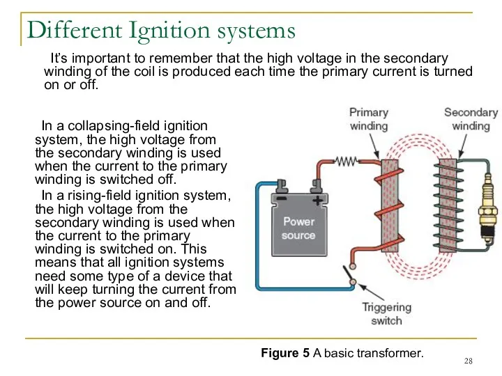
- 28. Different Ignition systems In a collapsing-field ignition system, the high voltage from the secondary winding is
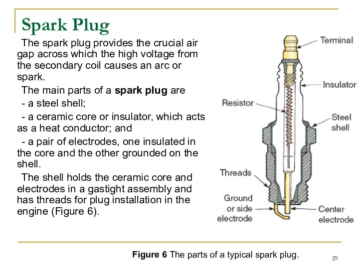
- 29. Spark Plug The spark plug provides the crucial air gap across which the high voltage from
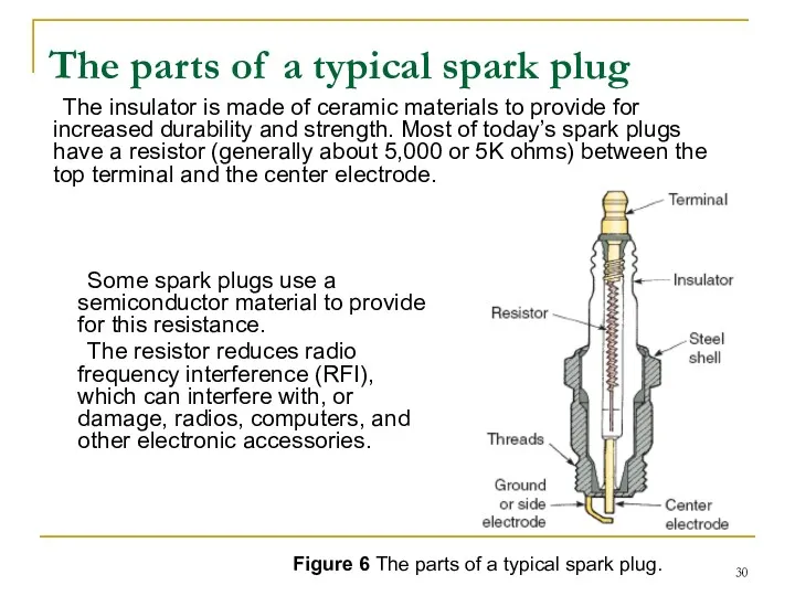
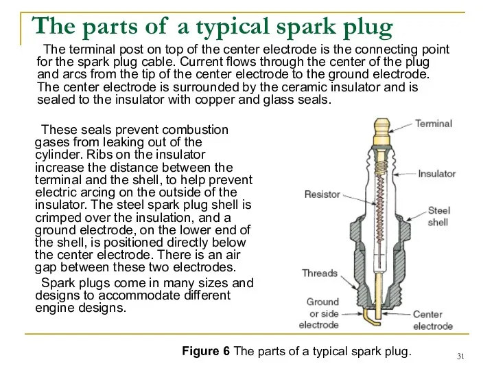
- 30. The insulator is made of ceramic materials to provide for increased durability and strength. Most of
- 31. The terminal post on top of the center electrode is the connecting point for the spark
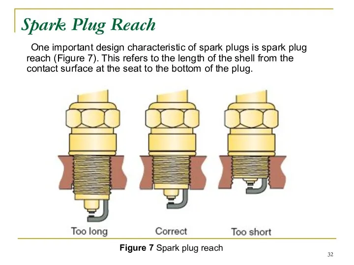
- 32. Spark Plug Reach One important design characteristic of spark plugs is spark plug reach (Figure 7).
- 33. If a plug’s reach is too short, its electrodes are in a pocket, and the arc
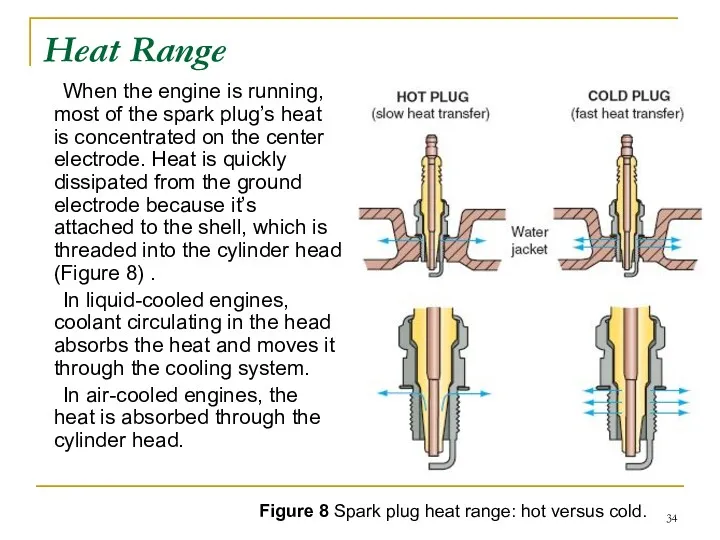
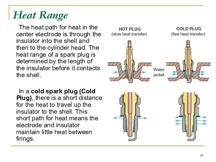
- 34. Heat Range When the engine is running, most of the spark plug’s heat is concentrated on
- 35. The heat path for heat in the center electrode is through the insulator into the shell
- 36. Figure 8 Spark plug heat range: hot versus cold. In a hot spark plug (Hot Plug),
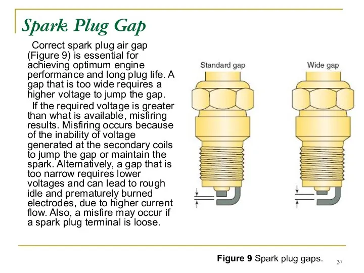
- 37. Spark Plug Gap Correct spark plug air gap (Figure 9) is essential for achieving optimum engine
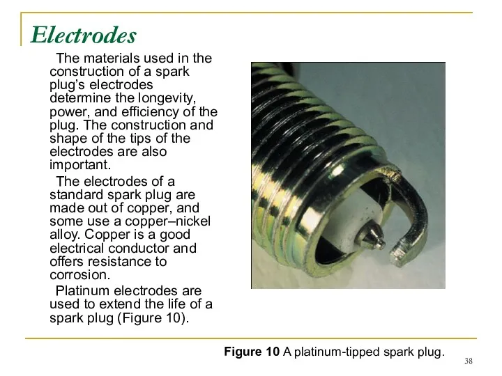
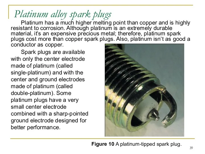
- 38. Electrodes The materials used in the construction of a spark plug’s electrodes determine the longevity, power,
- 39. Platinum has a much higher melting point than copper and is highly resistant to corrosion. Although
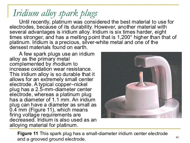
- 40. Until recently, platinum was considered the best material to use for electrodes, because of its durability.
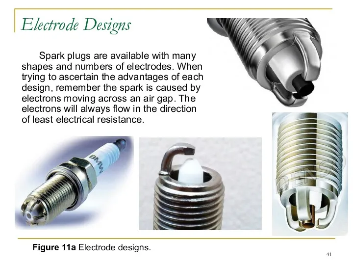
- 41. Electrode Designs Spark plugs are available with many shapes and numbers of electrodes. When trying to
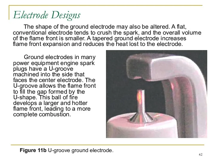
- 42. The shape of the ground electrode may also be altered. A flat, conventional electrode tends to
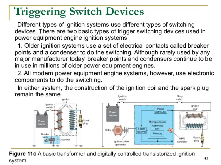
- 43. Triggering Switch Devices Different types of ignition systems use different types of switching devices. There are
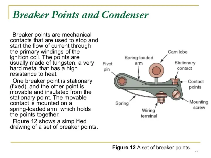
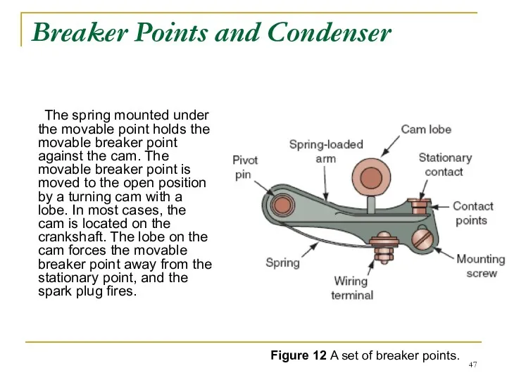
- 44. Breaker Points and Condenser Breaker points are mechanical contacts that are used to stop and start
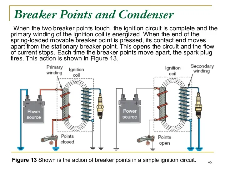
- 45. When the two breaker points touch, the ignition circuit is complete and the primary winding of
- 46. Figure 13 Shown is the action of breaker points in a simple ignition circuit. When the
- 47. The spring mounted under the movable point holds the movable breaker point against the cam. The
- 48. The condenser Another important component of a breakerpoints system is the condenser (also called a capacitor).
- 49. Figure 14 A typical battery-powered breaker point system. For these reasons, a condenser is used to
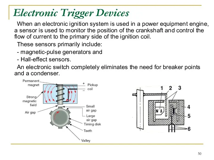
- 50. Electronic Trigger Devices When an electronic ignition system is used in a power equipment engine, a
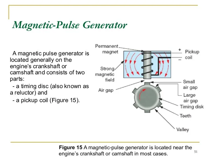
- 51. Magnetic-Pulse Generator A magnetic pulse generator is located generally on the engine’s crankshaft or camshaft and
- 52. Figure 15 A magnetic-pulse generator is located near the engine’s crankshaft or camshaft in most cases.
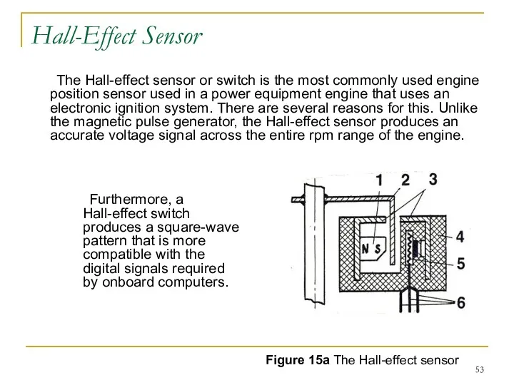
- 53. Hall-Effect Sensor The Hall-effect sensor or switch is the most commonly used engine position sensor used
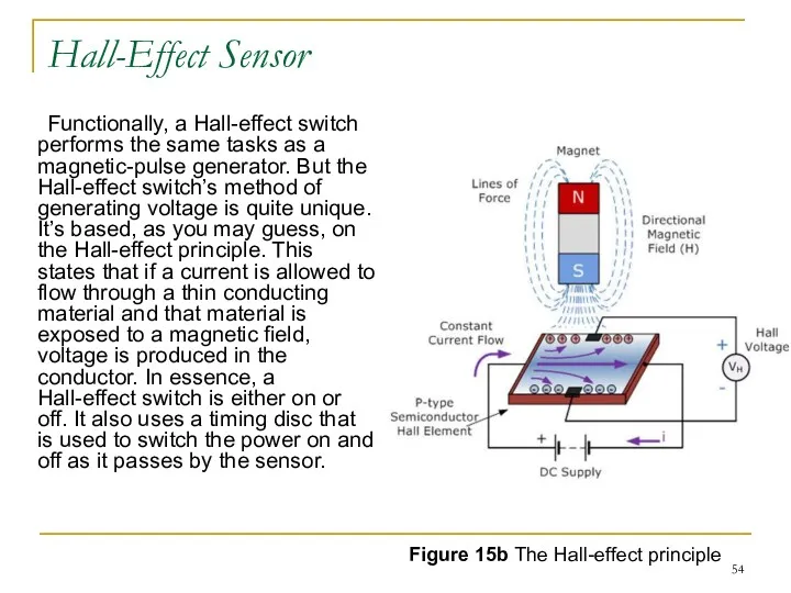
- 54. Hall-Effect Sensor Functionally, a Hall-effect switch performs the same tasks as a magnetic-pulse generator. But the
- 55. Stop Switch Different types of stop switches are found in different types of ignition systems. In
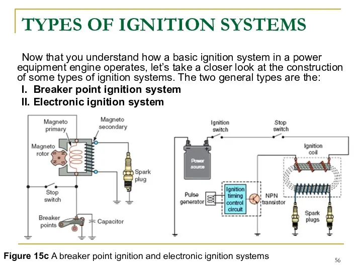
- 56. TYPES OF IGNITION SYSTEMS Now that you understand how a basic ignition system in a power
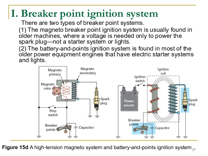
- 57. I. Breaker point ignition system There are two types of breaker point systems. (1) The magneto
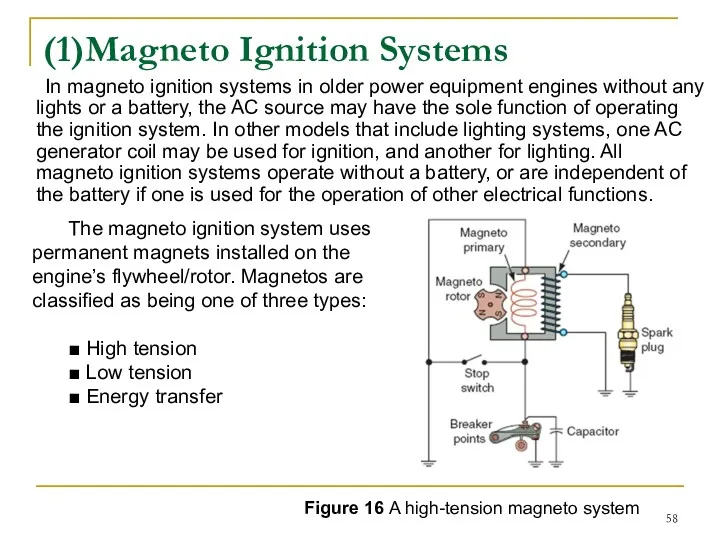
- 58. (1)Magneto Ignition Systems In magneto ignition systems in older power equipment engines without any lights or
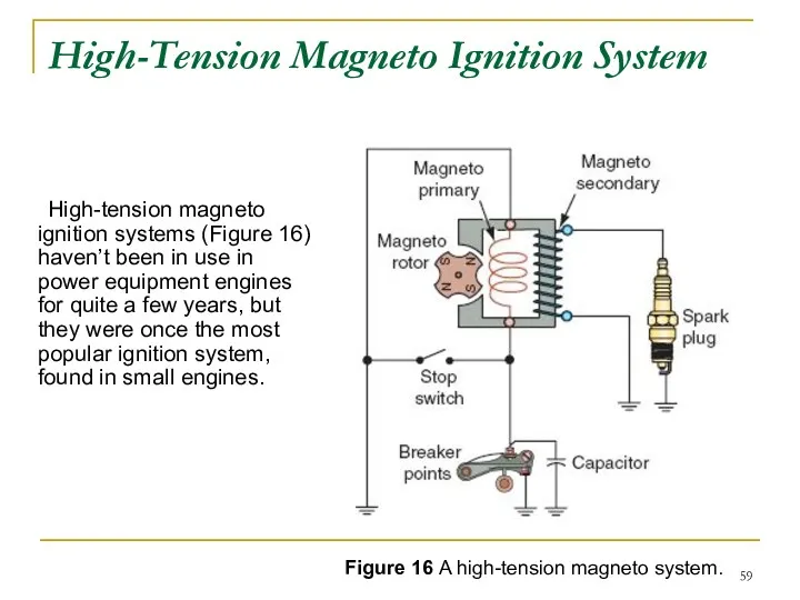
- 59. High-Tension Magneto Ignition System High-tension magneto ignition systems (Figure 16) haven’t been in use in power
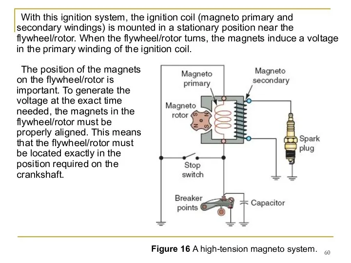
- 60. With this ignition system, the ignition coil (magneto primary and secondary windings) is mounted in a
- 61. Figure 16 A high-tension magneto system. The gap between the edge of the flywheel/rotor and the
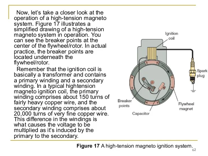
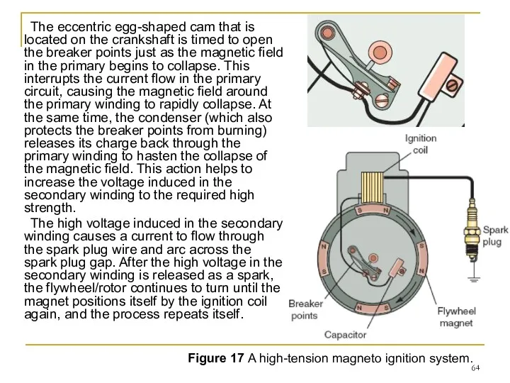
- 62. Now, let’s take a closer look at the operation of a high-tension magneto system. Figure 17
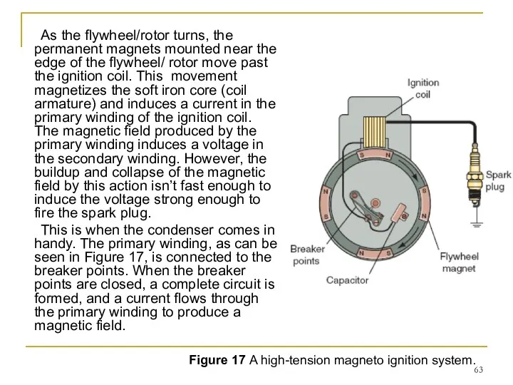
- 63. As the flywheel/rotor turns, the permanent magnets mounted near the edge of the flywheel/ rotor move
- 64. The eccentric egg-shaped cam that is located on the crankshaft is timed to open the breaker
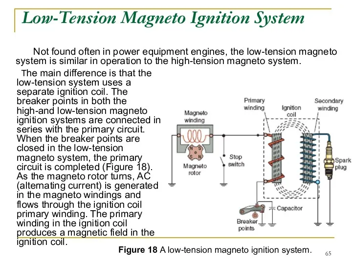
- 65. Low-Tension Magneto Ignition System The main difference is that the low-tension system uses a separate ignition
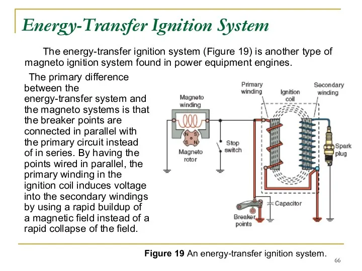
- 66. Energy-Transfer Ignition System The primary difference between the energy-transfer system and the magneto systems is that
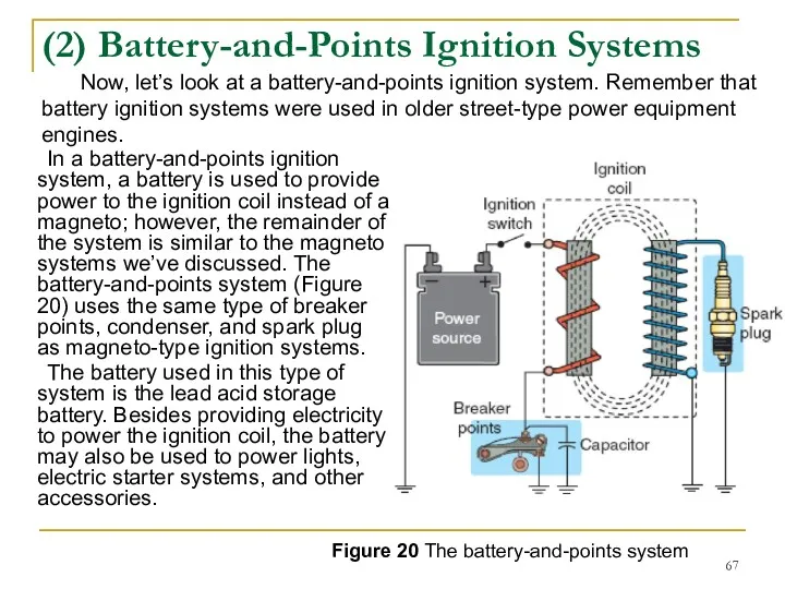
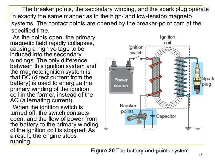
- 67. (2) Battery-and-Points Ignition Systems In a battery-and-points ignition system, a battery is used to provide power
- 68. As the points open, the primary magnetic field rapidly collapses, causing a high voltage to be
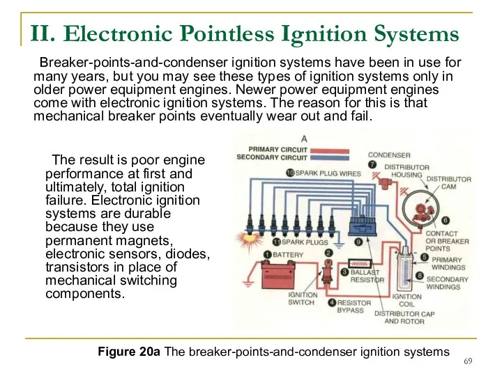
- 69. II. Electronic Pointless Ignition Systems Breaker-points-and-condenser ignition systems have been in use for many years, but
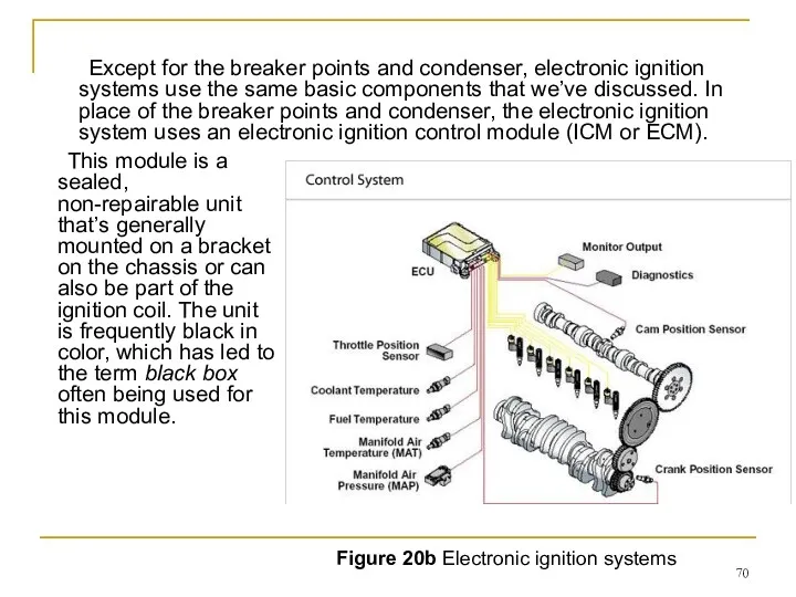
- 70. Except for the breaker points and condenser, electronic ignition systems use the same basic components that
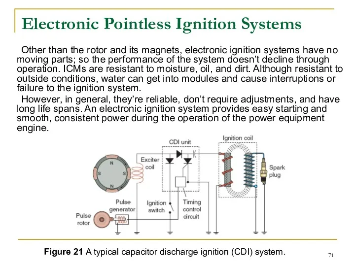
- 71. Electronic Pointless Ignition Systems Other than the rotor and its magnets, electronic ignition systems have no
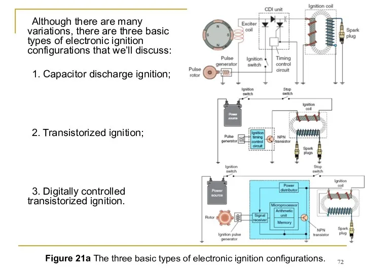
- 72. Although there are many variations, there are three basic types of electronic ignition configurations that we’ll
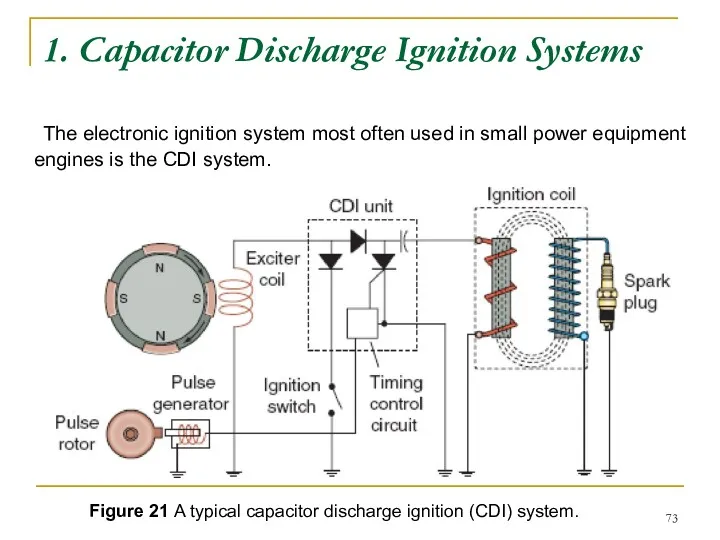
- 73. 1. Capacitor Discharge Ignition Systems The electronic ignition system most often used in small power equipment
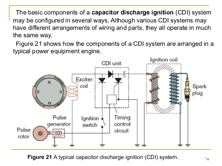
- 74. The basic components of a capacitor discharge ignition (CDI) system may be configured in several ways.
- 75. Figure 21 A typical capacitor discharge ignition (CDI) system. Note that the CDI system contains two
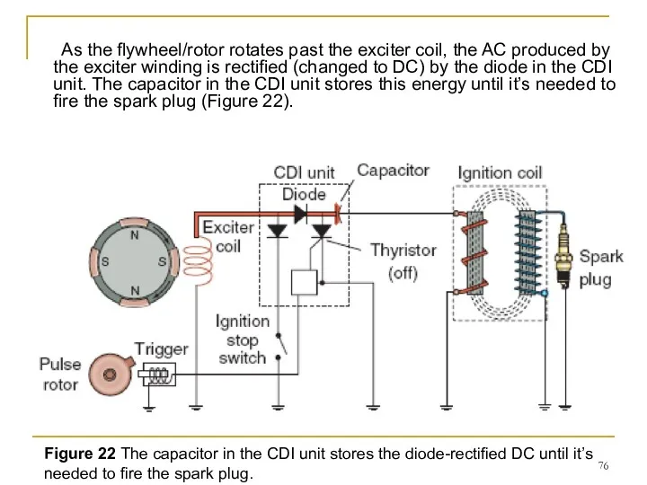
- 76. As the flywheel/rotor rotates past the exciter coil, the AC produced by the exciter winding is
- 77. As the flywheel/rotor magnet rotates past the trigger coil, a low-voltage signal is in the trigger
- 78. The electronic switch acts as the power source to the primary side of the circuit. This
- 79. Another type of CDI ignition system found in some power equipment engines is one that uses
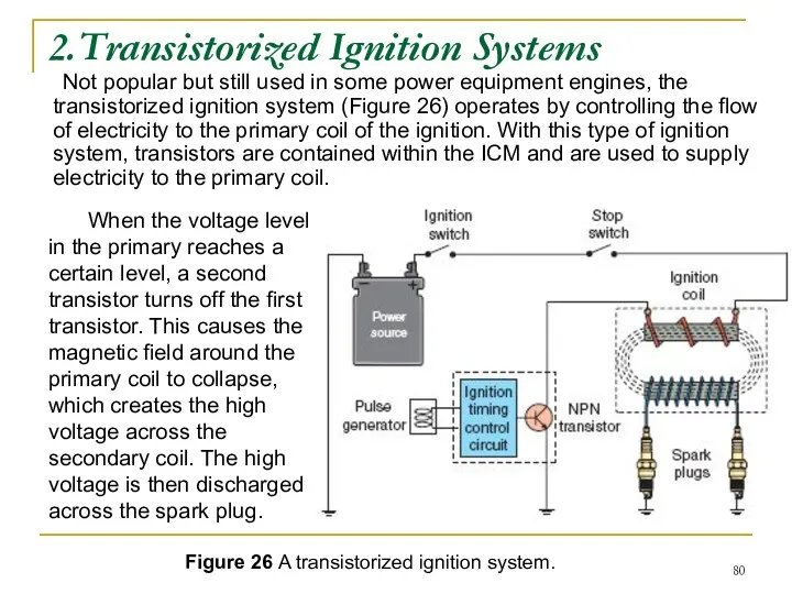
- 80. 2.Transistorized Ignition Systems Not popular but still used in some power equipment engines, the transistorized ignition
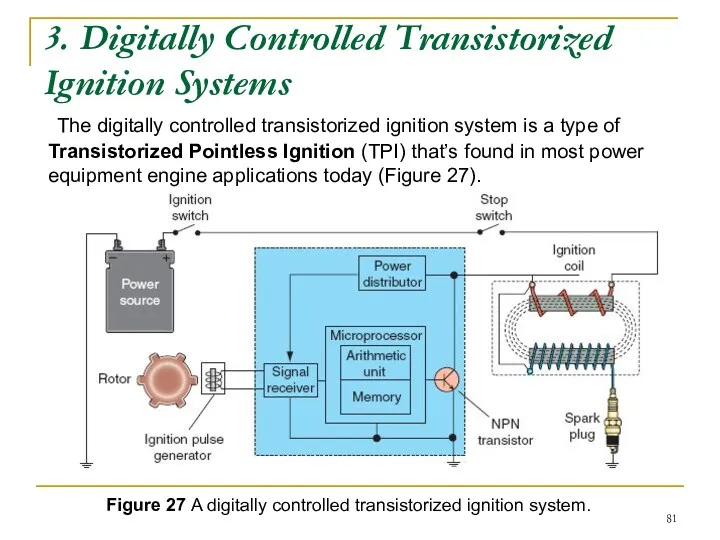
- 81. 3. Digitally Controlled Transistorized Ignition Systems The digitally controlled transistorized ignition system is a type of
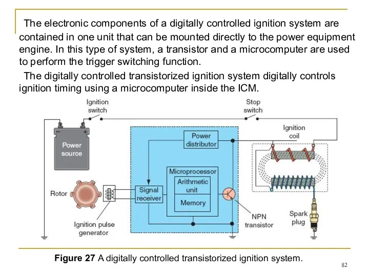
- 82. The electronic components of a digitally controlled ignition system are contained in one unit that can
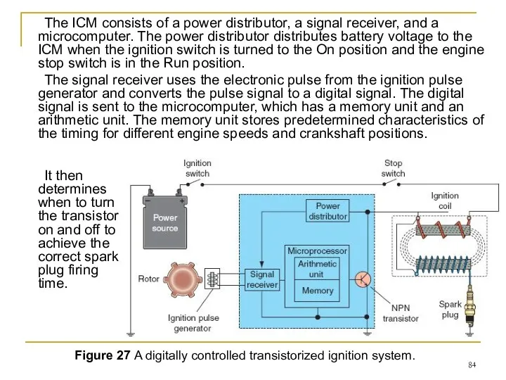
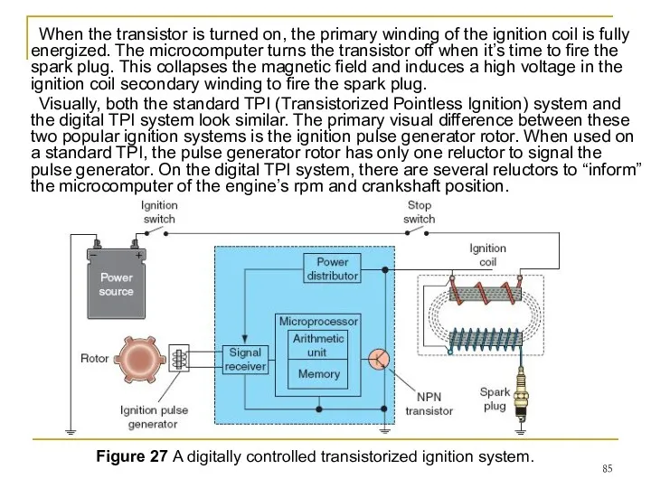
- 83. Figure 27 A digitally controlled transistorized ignition system. The microcomputer calculates the ideal ignition timing at
- 84. The ICM consists of a power distributor, a signal receiver, and a microcomputer. The power distributor
- 85. When the transistor is turned on, the primary winding of the ignition coil is fully energized.
- 86. Summary 1. The ignition system has three main functions: - first, it must generate an electrical
- 88. Скачать презентацию
INTRODUCTION
Do you remember the stages of operation in a two-stroke and
INTRODUCTION
Do you remember the stages of operation in a two-stroke and
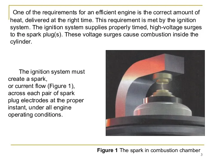
One of the requirements for an efficient engine is the correct
One of the requirements for an efficient engine is the correct
POWER EQUIPMENT ENGINE
IGNITION SYSTEMS
The sole purpose of an ignition system is
POWER EQUIPMENT ENGINE
IGNITION SYSTEMS
The sole purpose of an ignition system is
Three main functions of the ignition system
For each cylinder in
Three main functions of the ignition system
For each cylinder in
For an engine to produce the maximum amount of power it
For an engine to produce the maximum amount of power it
Therefore, the delivery of the spark must be timed to arrive
Therefore, the delivery of the spark must be timed to arrive
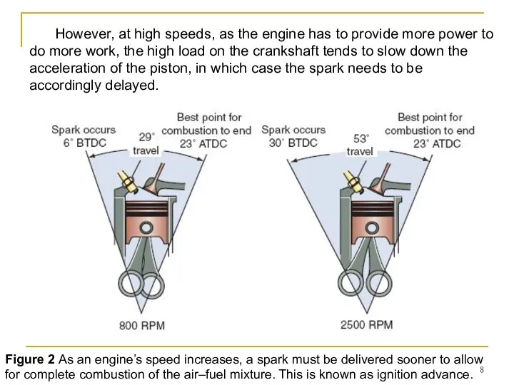
Figure 2 As an engine’s speed increases, a spark must be
Figure 2 As an engine’s speed increases, a spark must be
Figuring out when the spark should begin gets more complicated because
Figuring out when the spark should begin gets more complicated because
Ignition Timing
Ignition timing refers to the precise time spark occurs. It’s
Ignition Timing
Ignition timing refers to the precise time spark occurs. It’s
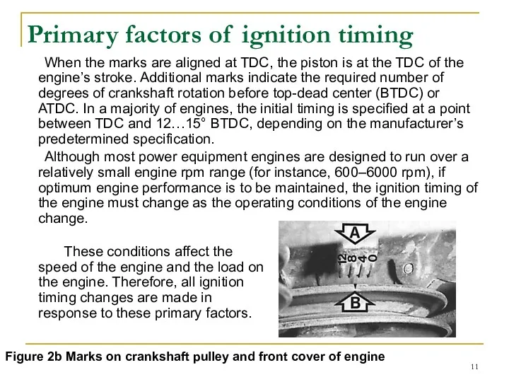
When the marks are aligned at TDC, the piston is at
When the marks are aligned at TDC, the piston is at
Ignition Timing Advance
Power equipment engines generally run at relatively stable engine
Ignition Timing Advance
Power equipment engines generally run at relatively stable engine
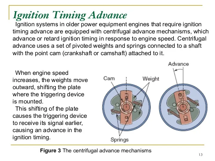
Ignition systems in older power equipment engines that require ignition timing
Ignition systems in older power equipment engines that require ignition timing
Electronic advance systems
Most all modern day power equipment engines that require
Electronic advance systems
Most all modern day power equipment engines that require
Engine rpm and Turbulence
At higher rpm, the crankshaft turns through more
Engine rpm and Turbulence
At higher rpm, the crankshaft turns through more
Engine Load
The load on an engine is related to the work
Engine Load
The load on an engine is related to the work
Firing Order in Multi-Cylinder Engines
Up to this point, we’ve focused primarily
Firing Order in Multi-Cylinder Engines
Up to this point, we’ve focused primarily
BASIC IGNITION SYSTEM
COMPONENTS
Figure 4 shows a simplified drawing of a basic
BASIC IGNITION SYSTEM
COMPONENTS
Figure 4 shows a simplified drawing of a basic
Power Sources
In power equipment engine ignition systems, there are just two
Power Sources
In power equipment engine ignition systems, there are just two
Power Sources
Remember that when a conductor wire is moved through a
Power Sources
Remember that when a conductor wire is moved through a
Ignition Switch
The ignition switch allows the power source to provide electrical
Ignition Switch
The ignition switch allows the power source to provide electrical

Ignition Coil
An ignition coil is essentially a transformer that consists of
Ignition Coil
An ignition coil is essentially a transformer that consists of
Ignition Coil
In an ignition coil, one end of the coil’s primary
Ignition Coil
In an ignition coil, one end of the coil’s primary
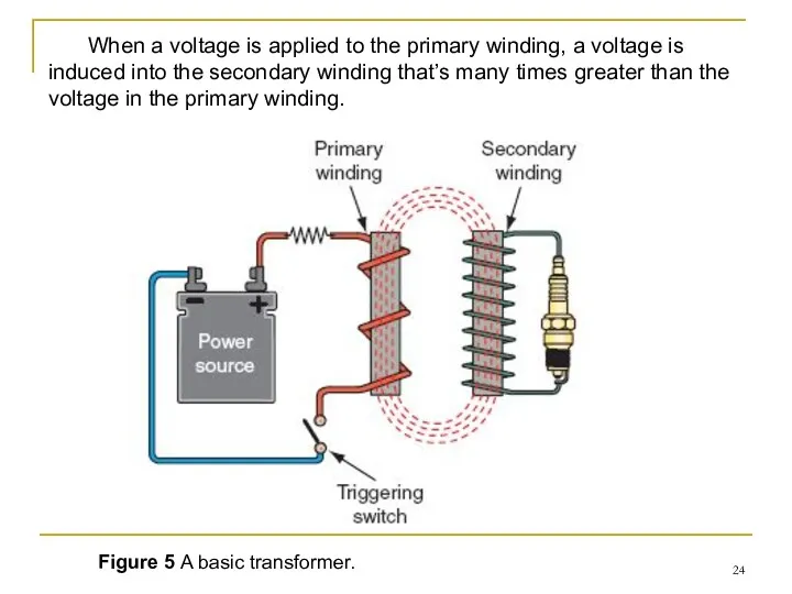
Figure 5 A basic transformer.
When a voltage is applied to
Figure 5 A basic transformer.
When a voltage is applied to
20,000–60,000 volts
If the current in the primary winding is switched
20,000–60,000 volts
If the current in the primary winding is switched
20,000–60,000 volts
Because the secondary winding of the coil has many more
20,000–60,000 volts
Because the secondary winding of the coil has many more
Different Ignition systems
The secondary winding of the coil is always connected
Different Ignition systems
The secondary winding of the coil is always connected
Different Ignition systems
In a collapsing-field ignition system, the high voltage from
Different Ignition systems
In a collapsing-field ignition system, the high voltage from
Spark Plug
The spark plug provides the crucial air gap across which
Spark Plug
The spark plug provides the crucial air gap across which
The insulator is made of ceramic materials to provide for increased
The insulator is made of ceramic materials to provide for increased
The terminal post on top of the center electrode is the
The terminal post on top of the center electrode is the
Spark Plug Reach
One important design characteristic of spark plugs is spark
Spark Plug Reach
One important design characteristic of spark plugs is spark
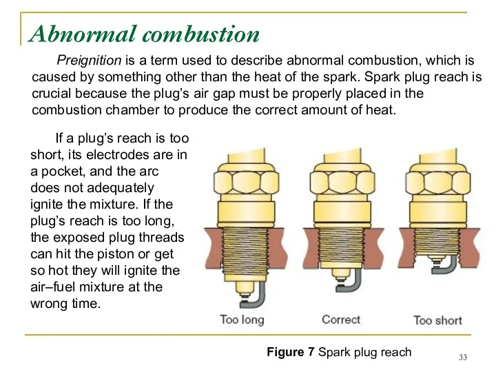
If a plug’s reach is too short, its electrodes are in
If a plug’s reach is too short, its electrodes are in
Heat Range
When the engine is running, most of the spark plug’s
Heat Range
When the engine is running, most of the spark plug’s
The heat path for heat in the center electrode is through
The heat path for heat in the center electrode is through
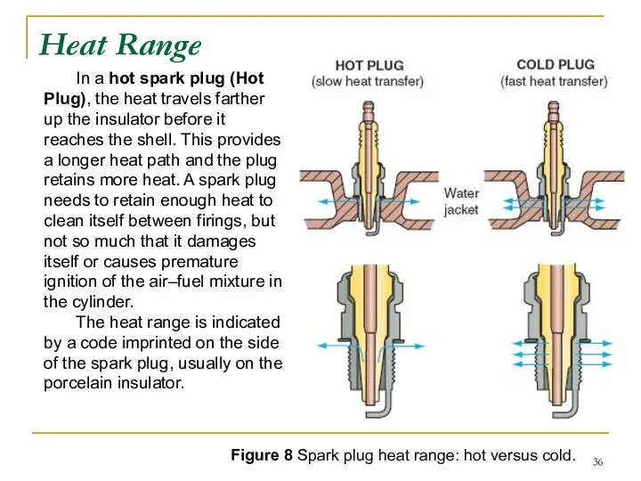
Figure 8 Spark plug heat range: hot versus cold.
In a hot
Figure 8 Spark plug heat range: hot versus cold.
In a hot
Spark Plug Gap
Correct spark plug air gap (Figure 9) is essential
Spark Plug Gap
Correct spark plug air gap (Figure 9) is essential
Electrodes
The materials used in the construction of a spark plug’s electrodes
Electrodes
The materials used in the construction of a spark plug’s electrodes
Platinum has a much higher melting point than copper and is
Platinum has a much higher melting point than copper and is
Until recently, platinum was considered the best material to use for
Until recently, platinum was considered the best material to use for
Electrode Designs
Spark plugs are available with many shapes and numbers of
Electrode Designs
Spark plugs are available with many shapes and numbers of
The shape of the ground electrode may also be altered. A
The shape of the ground electrode may also be altered. A
Triggering Switch Devices
Different types of ignition systems use different types of
Triggering Switch Devices
Different types of ignition systems use different types of
Breaker Points and Condenser
Breaker points are mechanical contacts that are used
Breaker Points and Condenser
Breaker points are mechanical contacts that are used
When the two breaker points touch, the ignition circuit is complete
When the two breaker points touch, the ignition circuit is complete
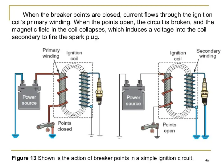
Figure 13 Shown is the action of breaker points in a
Figure 13 Shown is the action of breaker points in a
The spring mounted under the movable point holds the movable breaker
The spring mounted under the movable point holds the movable breaker

The condenser
Another important component of a breakerpoints system is the condenser
The condenser
Another important component of a breakerpoints system is the condenser
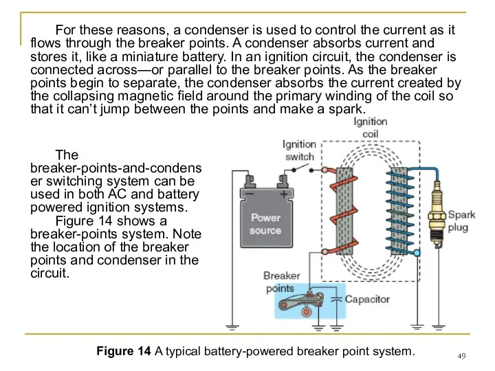
Figure 14 A typical battery-powered breaker point system.
For these reasons, a
Figure 14 A typical battery-powered breaker point system.
For these reasons, a
Electronic Trigger Devices
When an electronic ignition system is used in a
Electronic Trigger Devices
When an electronic ignition system is used in a
Magnetic-Pulse Generator
A magnetic pulse generator is located generally on the
Magnetic-Pulse Generator
A magnetic pulse generator is located generally on the
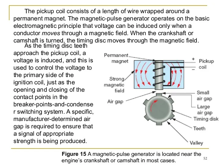
Figure 15 A magnetic-pulse generator is located near the engine’s crankshaft
Figure 15 A magnetic-pulse generator is located near the engine’s crankshaft
Hall-Effect Sensor
The Hall-effect sensor or switch is the most commonly used
Hall-Effect Sensor
The Hall-effect sensor or switch is the most commonly used
Hall-Effect Sensor
Functionally, a Hall-effect switch performs the same tasks as a
Hall-Effect Sensor
Functionally, a Hall-effect switch performs the same tasks as a
Stop Switch
Different types of stop switches are found in different types
Stop Switch
Different types of stop switches are found in different types
TYPES OF IGNITION SYSTEMS
Now that you understand how a basic ignition
TYPES OF IGNITION SYSTEMS
Now that you understand how a basic ignition
I. Breaker point ignition system
There are two types of breaker point
I. Breaker point ignition system
There are two types of breaker point
(1)Magneto Ignition Systems
In magneto ignition systems in older power equipment engines
(1)Magneto Ignition Systems
In magneto ignition systems in older power equipment engines
High-Tension Magneto Ignition System
High-tension magneto ignition systems (Figure 16) haven’t been
High-Tension Magneto Ignition System
High-tension magneto ignition systems (Figure 16) haven’t been
With this ignition system, the ignition coil (magneto primary and secondary
With this ignition system, the ignition coil (magneto primary and secondary
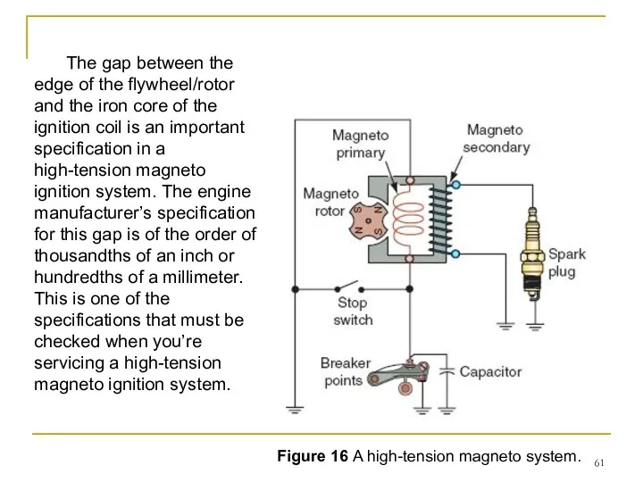
Figure 16 A high-tension magneto system.
The gap between the edge of
Figure 16 A high-tension magneto system.
The gap between the edge of
Now, let’s take a closer look at the operation of a
Now, let’s take a closer look at the operation of a
As the flywheel/rotor turns, the permanent magnets mounted near the edge
As the flywheel/rotor turns, the permanent magnets mounted near the edge
The eccentric egg-shaped cam that is located on the crankshaft is
The eccentric egg-shaped cam that is located on the crankshaft is
Low-Tension Magneto Ignition System
The main difference is that the low-tension system
Low-Tension Magneto Ignition System
The main difference is that the low-tension system
Energy-Transfer Ignition System
The primary difference between the energy-transfer system and the
Energy-Transfer Ignition System
The primary difference between the energy-transfer system and the
(2) Battery-and-Points Ignition Systems
In a battery-and-points ignition system, a battery is
(2) Battery-and-Points Ignition Systems
In a battery-and-points ignition system, a battery is
As the points open, the primary magnetic field rapidly collapses, causing
As the points open, the primary magnetic field rapidly collapses, causing
II. Electronic Pointless Ignition Systems
Breaker-points-and-condenser ignition systems have been in use
II. Electronic Pointless Ignition Systems
Breaker-points-and-condenser ignition systems have been in use
Except for the breaker points and condenser, electronic ignition systems use
Except for the breaker points and condenser, electronic ignition systems use
Electronic Pointless Ignition Systems
Other than the rotor and its magnets, electronic
Electronic Pointless Ignition Systems
Other than the rotor and its magnets, electronic
Although there are many variations, there are three basic types of
Although there are many variations, there are three basic types of
1. Capacitor Discharge Ignition Systems
The electronic ignition system most often used
1. Capacitor Discharge Ignition Systems
The electronic ignition system most often used
The basic components of a capacitor discharge ignition (CDI) system may
The basic components of a capacitor discharge ignition (CDI) system may
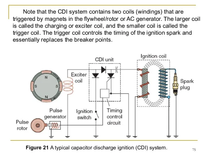
Figure 21 A typical capacitor discharge ignition (CDI) system.
Note that the
Figure 21 A typical capacitor discharge ignition (CDI) system.
Note that the
As the flywheel/rotor rotates past the exciter coil, the AC produced
As the flywheel/rotor rotates past the exciter coil, the AC produced
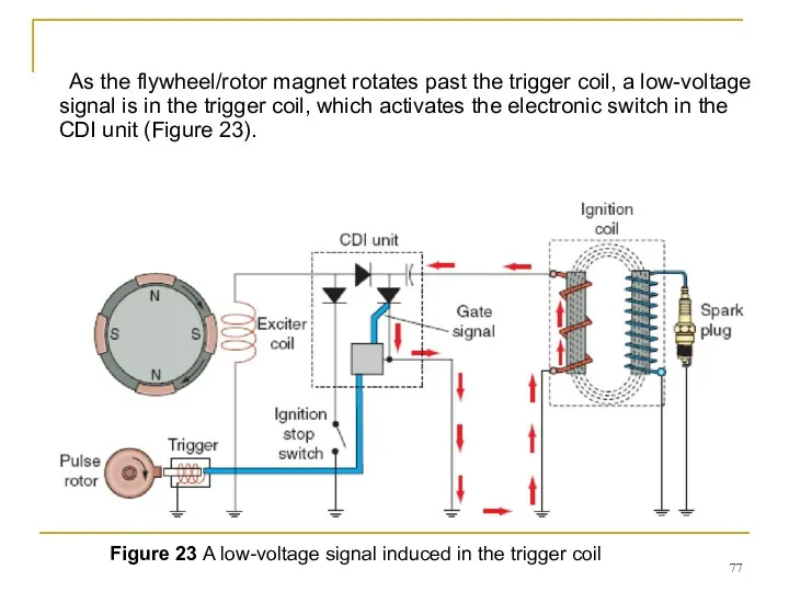
As the flywheel/rotor magnet rotates past the trigger coil, a low-voltage
As the flywheel/rotor magnet rotates past the trigger coil, a low-voltage
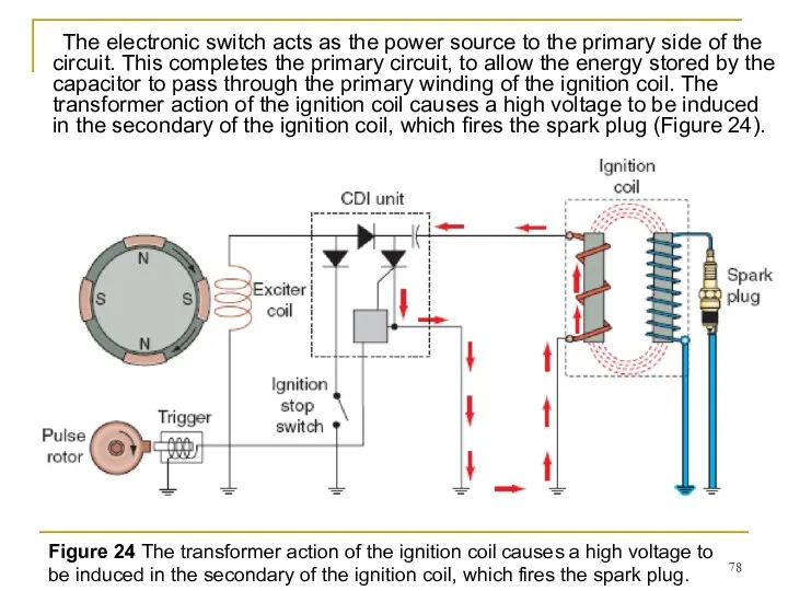
The electronic switch acts as the power source to the primary
The electronic switch acts as the power source to the primary
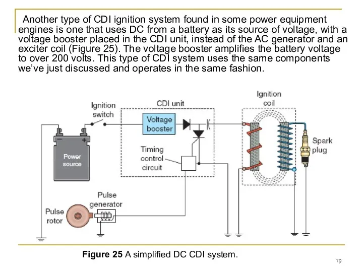
Another type of CDI ignition system found in some power equipment
Another type of CDI ignition system found in some power equipment
2.Transistorized Ignition Systems
Not popular but still used in some power equipment
2.Transistorized Ignition Systems
Not popular but still used in some power equipment
3. Digitally Controlled Transistorized Ignition Systems
The digitally controlled transistorized ignition system
3. Digitally Controlled Transistorized Ignition Systems
The digitally controlled transistorized ignition system
The electronic components of a digitally controlled ignition system are contained
The electronic components of a digitally controlled ignition system are contained
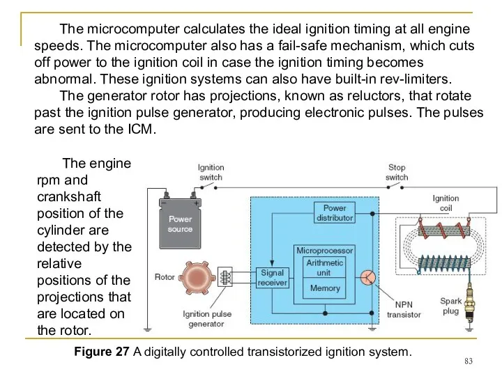
Figure 27 A digitally controlled transistorized ignition system.
The microcomputer calculates the
Figure 27 A digitally controlled transistorized ignition system.
The microcomputer calculates the
The ICM consists of a power distributor, a signal receiver, and
The ICM consists of a power distributor, a signal receiver, and
When the transistor is turned on, the primary winding of the
When the transistor is turned on, the primary winding of the
Summary
1. The ignition system has three main functions:
- first, it must
Summary
1. The ignition system has three main functions:
- first, it must
 Механическое оборудование и система вентиляции
 Быстрое преобразование Фурье. (Лекция 12)
 Простой механизм. Двигатель
 Модель атома водорода Бора . Постулаты Н. Бора. Квантовые генераторы
 Оптичні явища в природі
 Биофизика в современном мире на примере органа слуха
 Техническое обслуживание и текущий ремонт тормозной системы автомобиля
 Работа. Мощность. Энергия. 10 заданий
 Механическая работа и мощность. Подготовка к ЕГЭ
 Мастер класс Реализация компетентностного подхода в преподавании физики через организацию самостоятельных исследований при решении физических задач
 Физика и методы научного познания
 Презентация 5
 Коливання
 Жартылай өткізгіштер құрылғылар, күшейту каскадтары, электрондық және иондық құрылғылар
 Сборка электромагнита и испытание его действия. Лабораторная работа
 Работа и потенциальная энергия электростатического поля
 Электрический ток
 Струны. М-теория
 Технологічні процеси та обладнання для технічного обслуговування та поточного ремонту. Лекція №7
 Улаштування і технічне обслуговування ходової частини (10)
 Общественному смотр знаний в 9классе по разделу Механика.
 Электростатика. Электрические заряды
 Тепловые явления для учащихся 8 и 10 классов
 Плотность вещества 7 класс
 Что изучает физика? Некоторые физические термины
 Тоқ көздері. Бөгде күштер
 Изучение явления электромагнитной индукции
 Твердые сплавы. Маркировка. Примеры. Области применения