- Folds mechanics theory and practice

Содержание
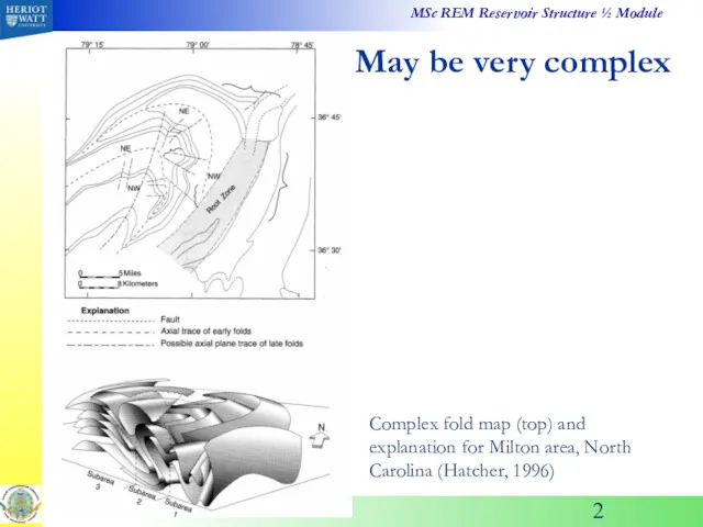
- 2. May be very complex Complex fold map (top) and explanation for Milton area, North Carolina (Hatcher,
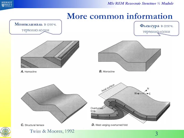
- 3. More common information Twiss & Moores, 1992 Флексура в отеч. терминологии Моноклиналь в отеч. терминологии
- 4. Hatcher, 1996 More common information Pumpelly’s rule: small-scale structure generally mimic larger-scale structures formed the same
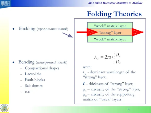
- 5. Folding Theories Buckling (продольный изгиб) Bending (поперечный изгиб) Compactional drapes Laccoliths Fault-blocks Salt domes etc were:
- 6. Single-Layer Buckling σ σ = σcrit scrit = f (thickness, ratio of stiffnesses) Layer is surrounded
- 7. Basics of Folding Mechanics Ortogonal Flexure Flexural-Shear Folding Passive-Shear Folding Volume-loss Folding: compressional solution bends formation!!
- 8. “Buckles” in the Laboratory These experiments reveal that EVERY plate tested begins to deflect from the
- 9. But Pushing on Rock Layers Makes Folds These rock-layer models were deformed at confining pressure as
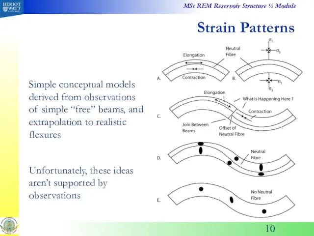
- 10. Strain Patterns Simple conceptual models derived from observations of simple “free” beams, and extrapolation to realistic
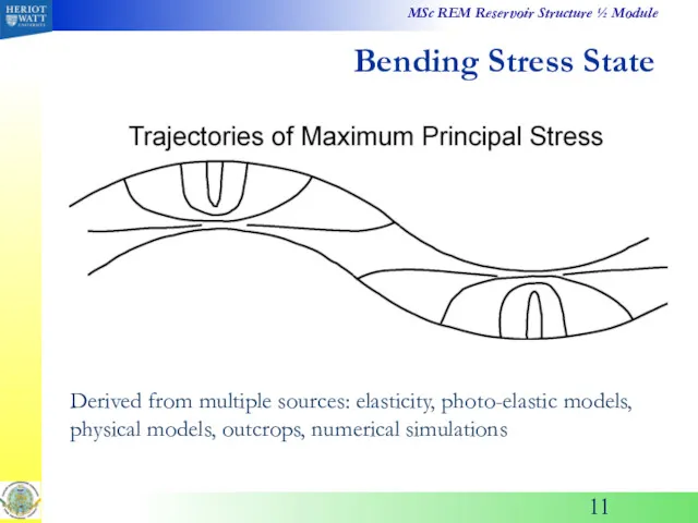
- 11. Bending Stress State Derived from multiple sources: elasticity, photo-elastic models, physical models, outcrops, numerical simulations
- 12. Pure Elastic Solution Map this solution onto finite flexure (after Hafner, 1951; Couples, 1977)
- 13. Photo-Elastic Models Gelatine balls: located in the glass with a piston on the top. Black bands
- 14. Rock Model Studies Crest of anticline in buckled single-layer of Leuders Limestone Note pattern of induced
- 15. Stress Pattern in Numerical Model of Flexure
- 16. Same Pattern in Numerical Models of Buckle Folds
- 17. Testing the Flexural Model Experimental models Numerical simulations Field observations Derive general prediction for fracture/ damage
- 18. Another Model Design: Details Machined steel blocks: perfect circular arcs, lubricated
- 19. Examples of Specimen Data Side jacket of lead, with scribed grid that records displacement during experiment
- 20. Effects of Multiple Layers As bedding-plane slip activates, pre-existing fabric elements are abandoned, and new ones
- 21. Observed Fabrics Flexural slip modifies the locations and amounts of induced damage L=limestone, D=dolostone, P=lead
- 22. Multiple Beams Develop Stack of paper cards, lubricated with graphite dust Slip develops only on some
- 23. Translations of Layers
- 24. Not Uniformly! Derived from distorted grids The rock layers move away from, and towards, the fold
- 25. εx Strains Vary Along Layers In these models, ex = evol
- 26. Multi-Layer Numerical Simulations
- 28. Скачать презентацию
May be very complex
Complex fold map (top) and explanation for Milton
May be very complex
Complex fold map (top) and explanation for Milton
More common information
Twiss & Moores, 1992
Флексура в отеч. терминологии
Моноклиналь в отеч.
More common information
Twiss & Moores, 1992
Флексура в отеч. терминологии
Моноклиналь в отеч.
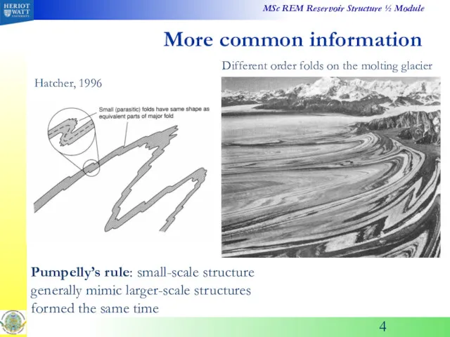
Hatcher, 1996
More common information
Pumpelly’s rule: small-scale structure generally mimic larger-scale structures
Hatcher, 1996
More common information
Pumpelly’s rule: small-scale structure generally mimic larger-scale structures
Folding Theories
Buckling (продольный изгиб)
Bending (поперечный изгиб)
Compactional drapes
Laccoliths
Fault-blocks
Salt domes
etc
were:
λd - dominant wavelength
Folding Theories
Buckling (продольный изгиб)
Bending (поперечный изгиб)
Compactional drapes
Laccoliths
Fault-blocks
Salt domes
etc
were:
λd - dominant wavelength
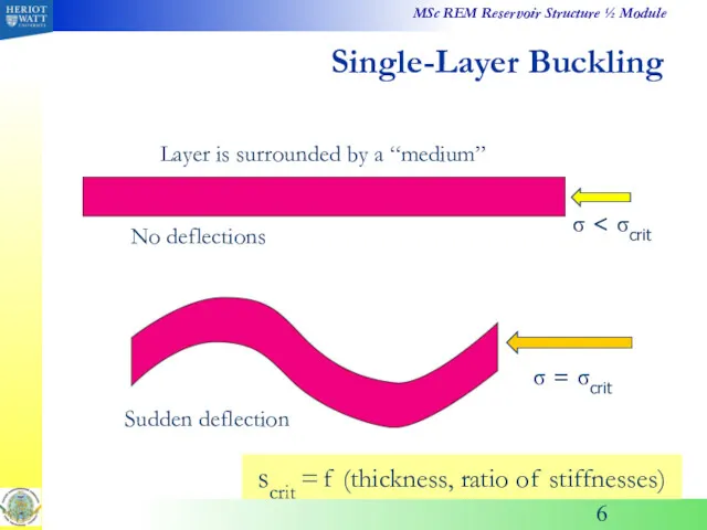
Single-Layer Buckling
σ < σcrit
σ = σcrit
scrit = f (thickness, ratio of
Single-Layer Buckling
σ < σcrit
σ = σcrit
scrit = f (thickness, ratio of
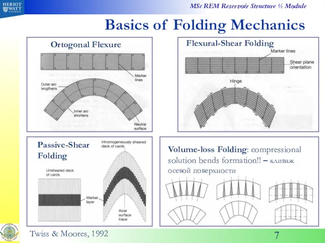
Basics of Folding Mechanics
Ortogonal Flexure
Flexural-Shear Folding
Passive-Shear Folding
Volume-loss Folding: compressional solution bends
Basics of Folding Mechanics
Ortogonal Flexure
Flexural-Shear Folding
Passive-Shear Folding
Volume-loss Folding: compressional solution bends
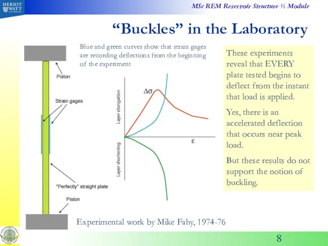
“Buckles” in the Laboratory
These experiments reveal that EVERY plate tested begins
“Buckles” in the Laboratory
These experiments reveal that EVERY plate tested begins
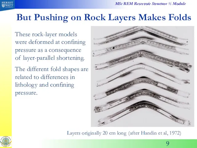
But Pushing on Rock Layers Makes Folds
These rock-layer models were deformed
But Pushing on Rock Layers Makes Folds
These rock-layer models were deformed
Strain Patterns
Simple conceptual models derived from observations of simple “free” beams,
Strain Patterns
Simple conceptual models derived from observations of simple “free” beams,
Bending Stress State
Derived from multiple sources: elasticity, photo-elastic models, physical models,
Bending Stress State
Derived from multiple sources: elasticity, photo-elastic models, physical models,
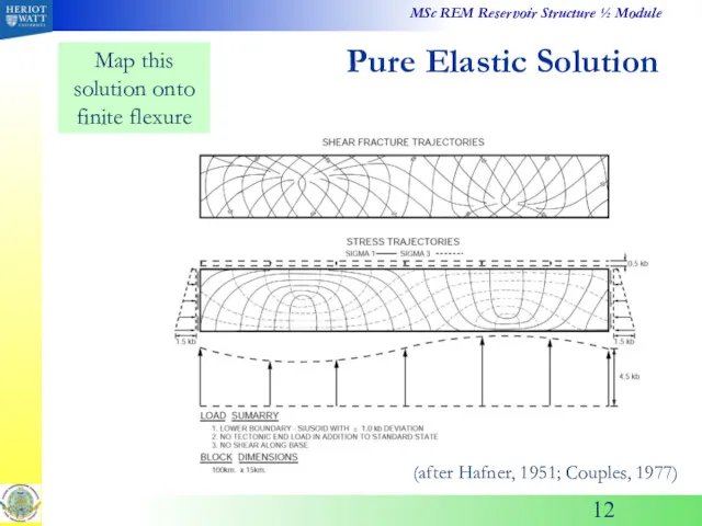
Pure Elastic Solution
Map this solution onto finite flexure
(after Hafner, 1951; Couples,
Pure Elastic Solution
Map this solution onto finite flexure
(after Hafner, 1951; Couples,
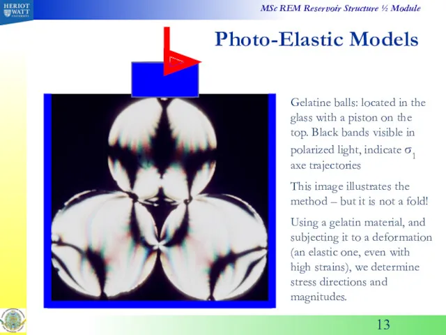
Photo-Elastic Models
Gelatine balls: located in the glass with a piston on
Photo-Elastic Models
Gelatine balls: located in the glass with a piston on
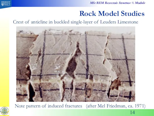
Rock Model Studies
Crest of anticline in buckled single-layer of Leuders Limestone
Note
Rock Model Studies
Crest of anticline in buckled single-layer of Leuders Limestone
Note
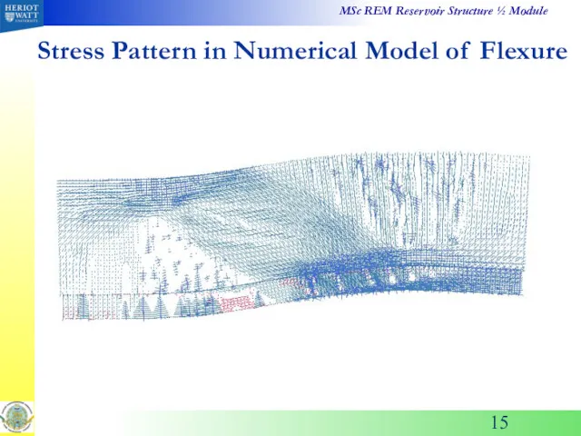
Stress Pattern in Numerical Model of Flexure
Stress Pattern in Numerical Model of Flexure
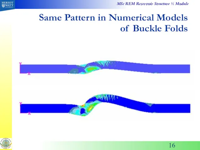
Same Pattern in Numerical Models of Buckle Folds
Same Pattern in Numerical Models of Buckle Folds
Testing the Flexural Model
Experimental models
Numerical simulations
Field observations
Derive general prediction for fracture/
Testing the Flexural Model
Experimental models
Numerical simulations
Field observations
Derive general prediction for fracture/
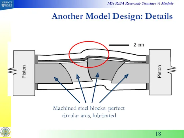
Another Model Design: Details
Machined steel blocks: perfect circular arcs, lubricated
Another Model Design: Details
Machined steel blocks: perfect circular arcs, lubricated
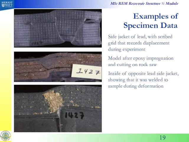
Examples of Specimen Data
Side jacket of lead, with scribed grid that
Examples of Specimen Data
Side jacket of lead, with scribed grid that
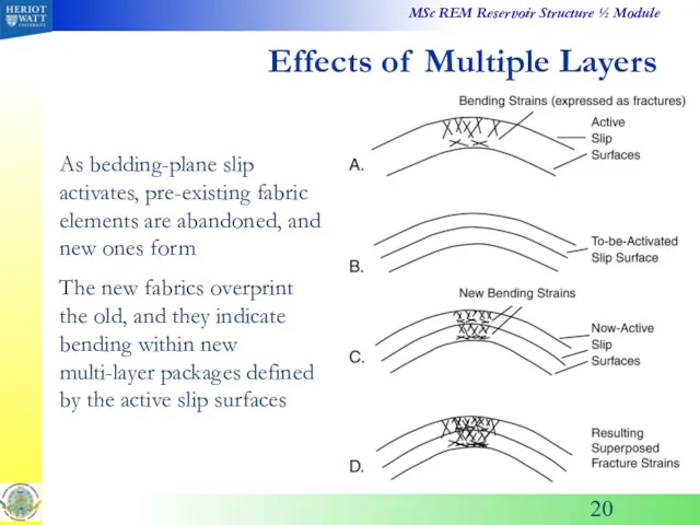
Effects of Multiple Layers
As bedding-plane slip activates, pre-existing fabric elements are
Effects of Multiple Layers
As bedding-plane slip activates, pre-existing fabric elements are
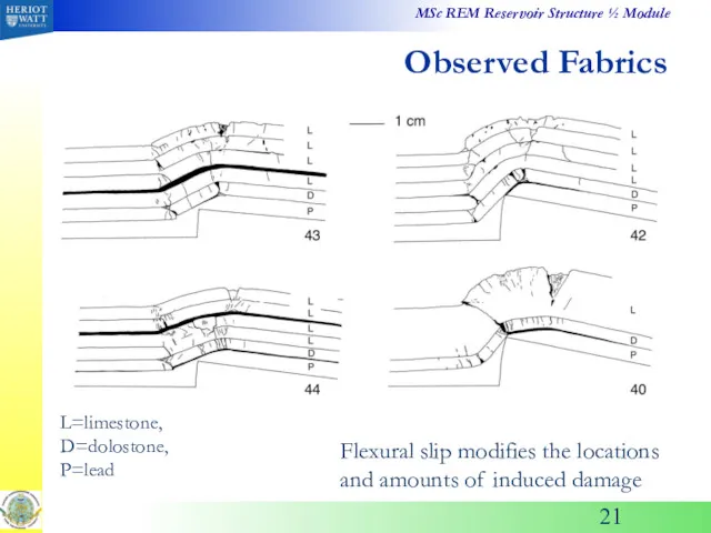
Observed Fabrics
Flexural slip modifies the locations and amounts of induced damage
L=limestone,
Observed Fabrics
Flexural slip modifies the locations and amounts of induced damage
L=limestone,
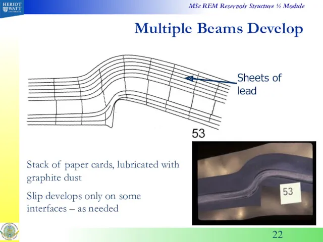
Multiple Beams Develop
Stack of paper cards, lubricated with graphite dust
Slip develops
Multiple Beams Develop
Stack of paper cards, lubricated with graphite dust
Slip develops
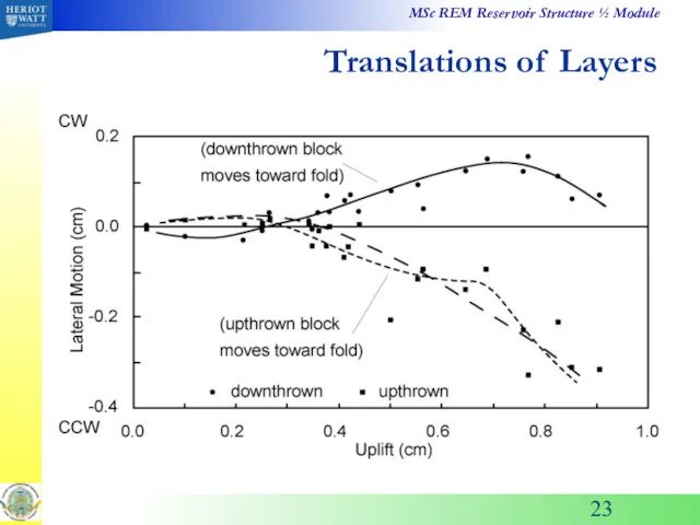
Translations of Layers
Translations of Layers
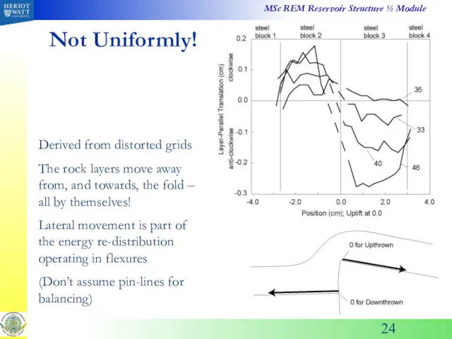
Not Uniformly!
Derived from distorted grids
The rock layers move away from, and
Not Uniformly!
Derived from distorted grids
The rock layers move away from, and
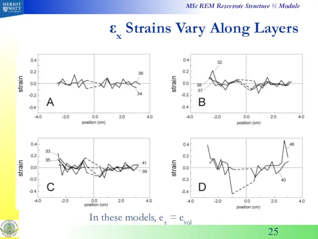
εx Strains Vary Along Layers
In these models, ex = evol
εx Strains Vary Along Layers
In these models, ex = evol
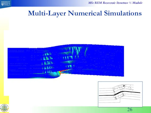
Multi-Layer Numerical Simulations
Multi-Layer Numerical Simulations
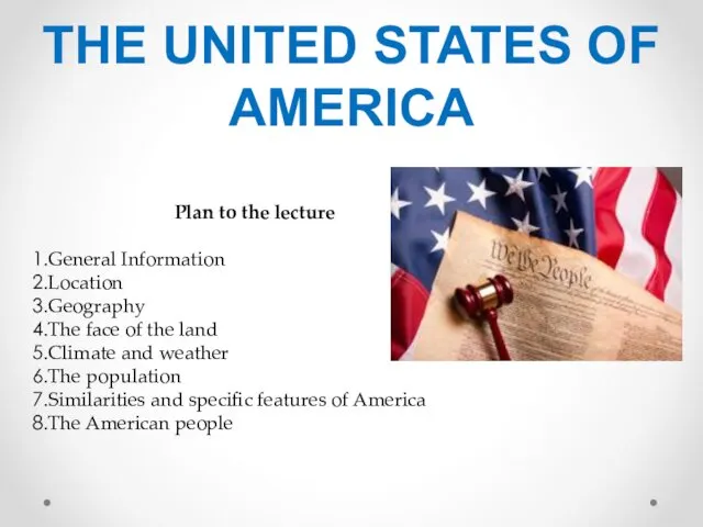 The United States of America
 Интеллектуальная игра по географии России
 Течения в океане
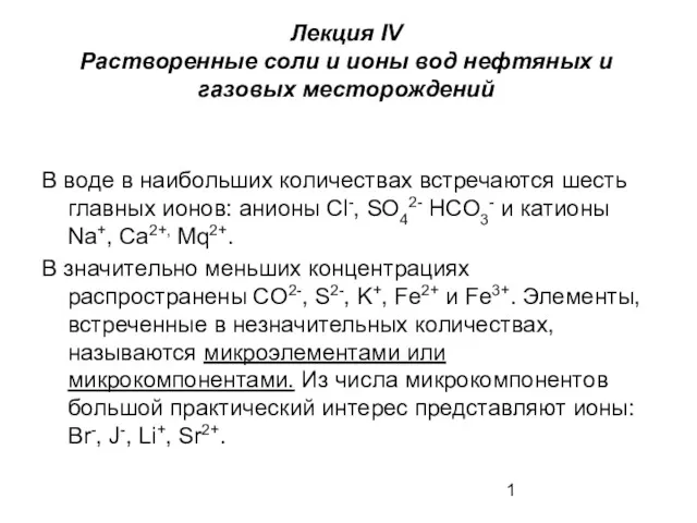 Растворенные соли и ионы вод нефтяных и газовых месторождений. (Лекция 4)
 Атмосферные явления
 Образование почв и их разнообразие
 Мой город Сочи
 Японія
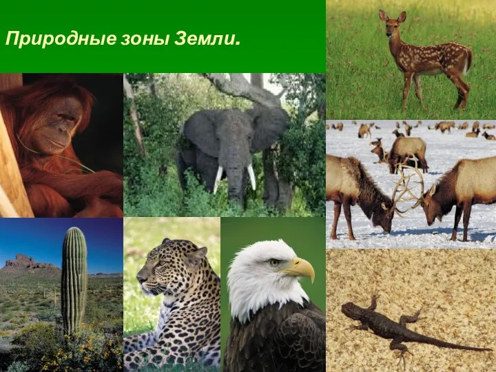 Природные зоны Земли
 Туристична індустрія Рівненської області
 Мұхиттар температурасы
 Хвойный лес. Тайга
 Качественные политические изменения на карте мира с 1950 года
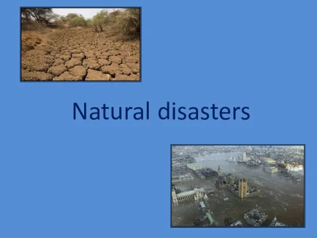 Natural disasters
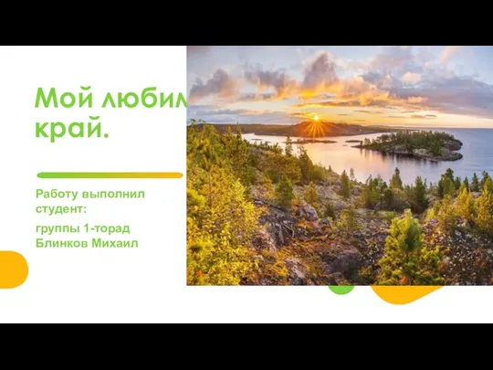 Удивительные места Карелии
 Атмосферное давление и ветер (урок)
 Бразилия, Бразилия Федеративтік Республикасы
 Смерчи, торнадо
 Молдова Республикасы
 Город Золотого кольца Кострома
 Чтение топографических карт
 Объекты природного наследия Африки
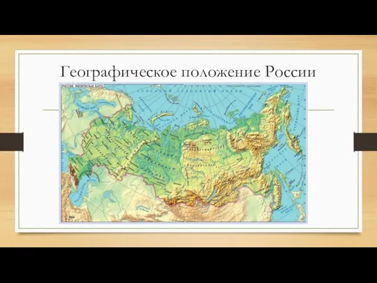 Географическое положение России. 8 класс
 Атмосферные осадки
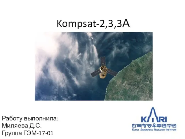 Спутники Kompsat-2,3,3А
 Этническая мозаика Восточной Сибири
 Агропромышленный комплекс (АПК)
 Особые формы залегания осадочных горных пород. Тема 10