- Arduino Basics. Goals of Lab #3

Содержание
- 2. Goals of Lab #3 ● Learn how the programming takes place ● Excercises about: Learn about
- 3. Intro to Arduino
- 4. Installing the IDE
- 5. Connect your Arduino
- 6. The Arduino IDE
- 7. 1: Select serial port
- 8. 2: Select Arduino model
- 9. Programming an Arduino From the File menu, choose Open and select the code you want to
- 10. Programming workflow
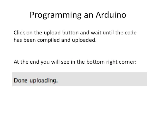
- 11. Programming an Arduino Click on the upload button and wait until the code has been compiled
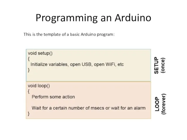
- 12. Programming an Arduino This is the template of a basic Arduino program:
- 13. Pre-lab #3
- 14. Resistor Resistors "resist" the flow of electricity, or current. The orientation in the circuit does not
- 15. Voltage Sources The Arduino has two constant voltage sources that we will use. The first is
- 16. Lab #3
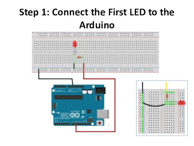
- 17. Step 1: Connect the First LED to the Arduino The first step is to connect the
- 18. Step 1: Connect the First LED to the Arduino
- 19. Schematic
- 20. CODE
- 21. Task #2 - Traffic Light Circuit The equipment I have used in this Arduino traffic light
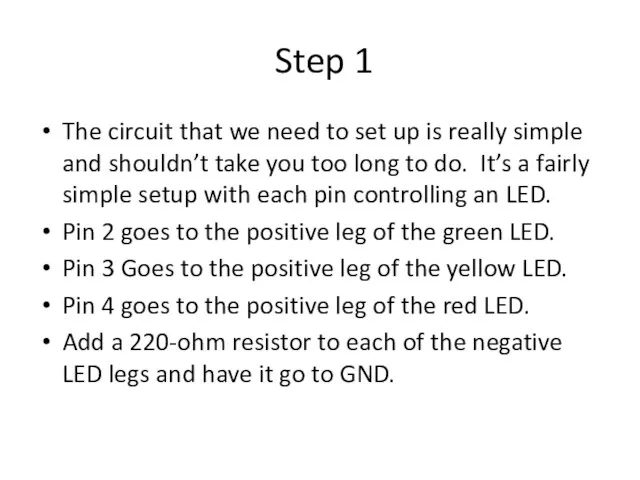
- 22. Step 1 The circuit that we need to set up is really simple and shouldn’t take
- 23. Diagram
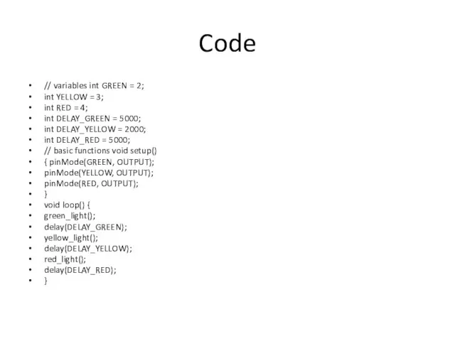
- 24. Code // variables int GREEN = 2; int YELLOW = 3; int RED = 4; int
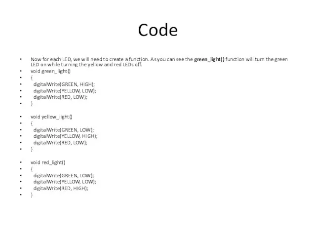
- 25. Code Now for each LED, we will need to create a function. As you can see
- 27. Скачать презентацию
Goals of Lab #3
● Learn how the programming takes place
Goals of Lab #3
● Learn how the programming takes place
Intro to Arduino
Intro to Arduino
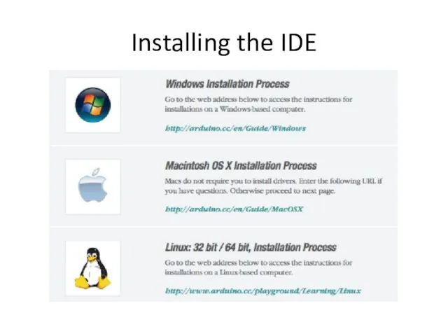
Installing the IDE
Installing the IDE
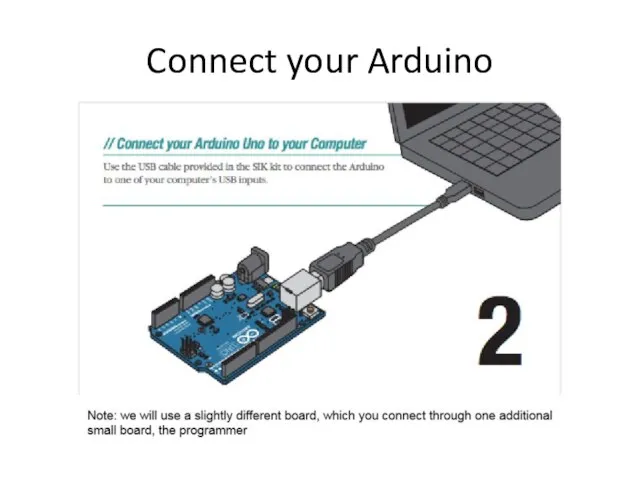
Connect your Arduino
Connect your Arduino
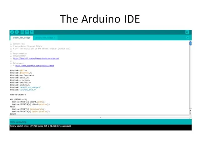
The Arduino IDE
The Arduino IDE
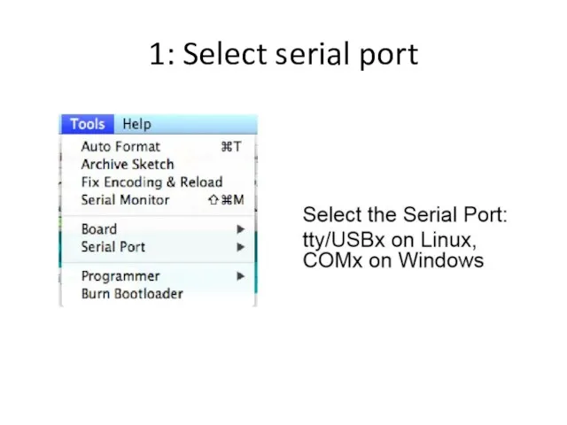
1: Select serial port
1: Select serial port
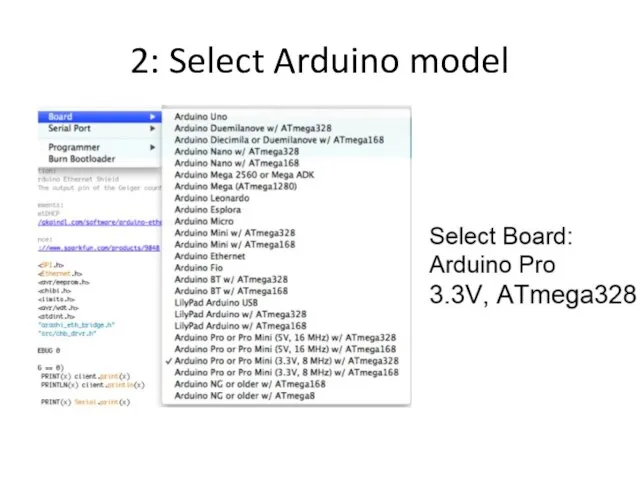
2: Select Arduino model
2: Select Arduino model
Programming an Arduino
From the File menu, choose Open and select
Programming an Arduino
From the File menu, choose Open and select
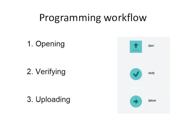
Programming workflow
Programming workflow
Programming an Arduino
Click on the upload button and wait until
Programming an Arduino
Click on the upload button and wait until
Programming an Arduino
This is the template of a basic Arduino
Programming an Arduino
This is the template of a basic Arduino
Pre-lab #3
Pre-lab #3
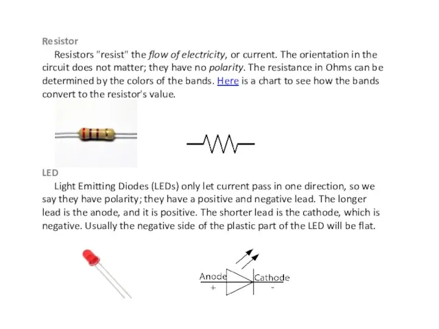
Resistor
Resistors "resist" the flow of electricity, or current. The
Resistor
Resistors "resist" the flow of electricity, or current. The
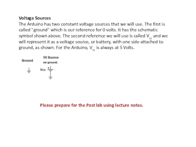
Voltage Sources
The Arduino has two constant voltage sources that we
Voltage Sources
The Arduino has two constant voltage sources that we
Lab #3
Lab #3
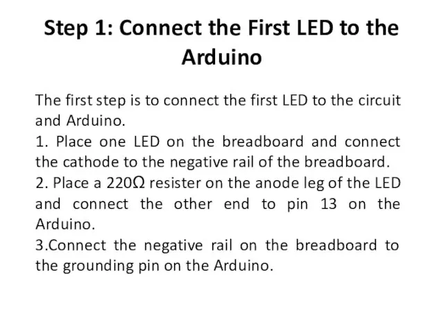
Step 1: Connect the First LED to the Arduino
The first step
Step 1: Connect the First LED to the Arduino
The first step
Step 1: Connect the First LED to the Arduino
Step 1: Connect the First LED to the Arduino
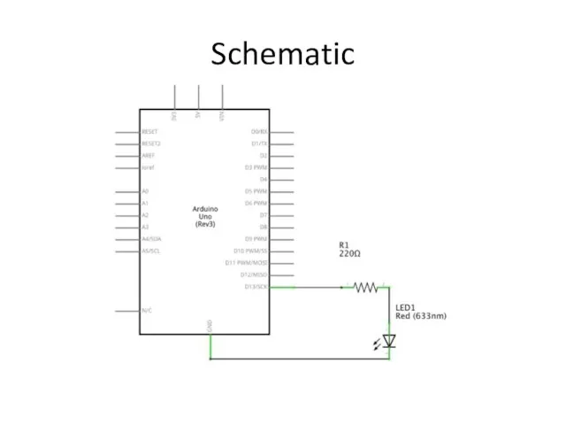
Schematic
Schematic
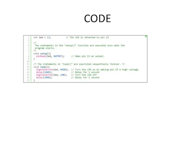
CODE
CODE
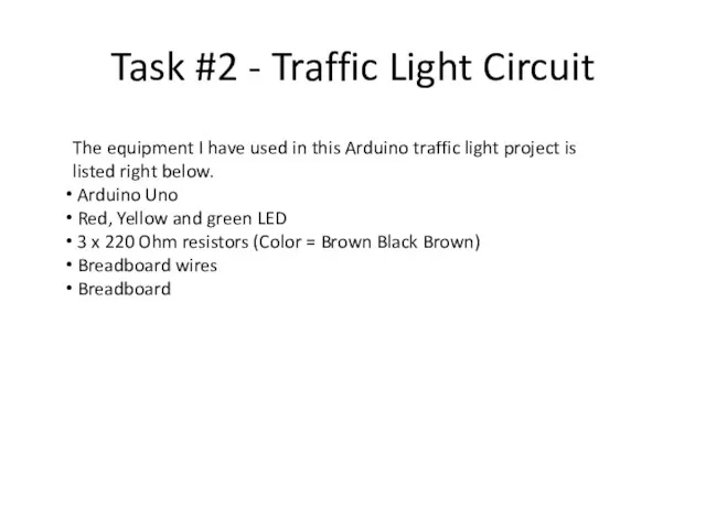
Task #2 - Traffic Light Circuit
The equipment I have used in
Task #2 - Traffic Light Circuit
The equipment I have used in
Step 1
The circuit that we need to set up is
Step 1
The circuit that we need to set up is
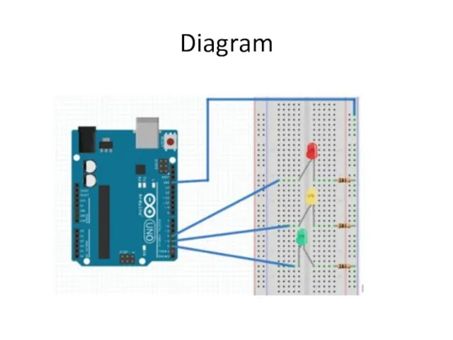
Diagram
Diagram
Code
// variables int GREEN = 2;
int YELLOW = 3;
int RED
Code
// variables int GREEN = 2;
int YELLOW = 3;
int RED
Code
Now for each LED, we will need to create a function.
Code
Now for each LED, we will need to create a function.
 Презентация проекта От здорового учителя к здоровому ученику
 Praxiserkundungsprojekt. Selbstevaluation von Lernenden im Unterricht
 Национальный проект Наука
 Направления подготовки ШГПУ на 2020 год, г. Шадринск
 Наш класс
 Реки, наполняющие вселенную мудростью. Интеллектуальная игра, посвященная Году библиотек
 Процедура заселения иногородних обучающихся в общежития КФУ
 Проект урока литературного чтения 2 класс
 Результативность деятельности кружков в 2015-2016 учебном
 Теоретические концепции научных исследований
 Добро пожаловать в Компьютерную Академию ТОР
 Свидетельство о государственной аккредитации вуза
 Обществознание. ЕГЭ 2017/2018
 В гости к Лесовичку
 Основы моделирования
 Знакомство с нормативной основой государственной (итоговой) аттестации выпускников 9 классов
 Ambassador lecturer. Your name company & position
 Бесплатные программы дополнительного образования
 Повышение качества образования.
 Стажировка от Сеченовского университета
 Организация учебной деятельности студентов
 Научные и организационные основы ОРМ
 Корпорация М. Программа развития факультета
 Природа моего края
 Требования к оформлению реферата
 Организация внеурочной деятельности в работе с одарёнными детьми
 Дипломная работа
 Минский государственный автомеханический колледж имени академика М.С. Высоцкого