- M –Project Training Manual

Содержание
- 2. 1. Precaution Follow these special safety precautions during repair or inspection. Although the microwave oven is
- 3. 1. Precaution 1-2. Safety Precaution Safety Precaution refers to Precaution and Warning and it does not
- 4. 1. Precaution In case gas is leaked, do not touch the power plug or the oven
- 5. 1-3. Precaution before repair 1. In case the oven is operable, the leakage of electronic waves
- 6. 1-4. Precaution during repair 5. If the fuse is blown by interlock monitor switch, replace all
- 7. 1-5. Precaution after repair 1. Do not connect the power cord which does not have earthed
- 8. Satisfaction of performance and speed with Multi Heat Source Compact Oven with All-In-One function Time &
- 9. 2. Features and Specifications Multi Rack Top Control Drop Down Door Tact & Dial Control Orange
- 10. Speed Cooking by 5 heat sources → 4 times reduction of cooking time with electric oven.
- 11. Distribution Fan (Stirrer) cooking manner → Effective Space Expansion, More sanitary [Distribution Fan] VS [Conventional: Turntable]
- 12. Improved Display Function → Convenience of menu selection Audio Style Icon Layout Mode Selection Dial Time
- 13. Steam Cleaning → Sanitary cooking - Cleaning particles inside by steam ※ Anti-virus ceramic coating (Sanitation
- 14. - Compact Oven + Cook top + Warmer/Drawer Total solution of cooking with cook top added
- 15. 2-3. Specifications 2. Features and Specifications
- 16. 2. Features and Specifications
- 17. 2. Features and Specifications
- 18. 3. Features and Installation 3-1. Functions ** Be aware of the followings first before operating the
- 19. 3-2. How to install the oven * Click the icon below to see how to install
- 20. 4. Disassembly and Reassembly 4-1. Preparations Basically, the followings are required to disassemble and reassemble the
- 21. 4-3. Replacement of High voltage transformer 1. Follow the order in article 1-4 of 4-2. 2.
- 22. 4. Disassembly and Reassembly 4-6. Replacement of A’SSY Main PCB 1. Follow the order in article
- 23. 4. Disassembly and Reassembly 4-8. Replacement of Ass’y Damper 1. Follow the order in article 1-4
- 24. 4. Disassembly and Reassembly 4-10. Replacement of Stirrer Motor 1. Follow the order in article 1-3
- 25. 4. Disassembly and Reassembly 4-11. Replacement of Ass’y Door 1. Lift up the decoration from the
- 26. 5. Alignment and Adjustments Precaution 1. High voltage is present at the high voltage terminals during
- 27. 5. Alignment and Adjustments 5-2. Magnetron Continuity checks on magnetron can indicate an open filament and
- 28. 5. Alignment and Adjustments 5-3. High Voltage Capacitor 1. Check continuity of the capacitor with the
- 29. 5. Alignment and Adjustments 5-5. Main relay and power control relay The relays are located on
- 30. 5. Alignment and Adjustments 5-7. Adjustment of Primary switch, Door sensing switch and monitor switch
- 31. 5. Alignment and Adjustments Caution Personnel should not allow exposure to microwave radiation from microwave generator
- 32. 5. Alignment and Adjustments The output power of the magnetron can be measured by performing a
- 33. 5. Alignment and Adjustments The microwave heat distribution can be checked indirectly by measuring the water
- 34. 5. Alignment and Adjustments Pour 275±15cc of 20±5°C(68±9°F) water in a beaker which is graduated to
- 35. 5. Alignment and Adjustments Do not exceed the limited scale. The test probe must be held
- 36. 6. Error Code
- 37. 7. Troubleshooting (Microwave Oven) MWO does not operate. Is Fuse OK? Are CON1 TCO & MONITOR
- 38. 7. Troubleshooting (Oven Mode) Oven Mode does not work. Is Fuse OK? Are CON1 TCO &
- 39. 7. Troubleshooting (Ass’y Display) Ass’y Display does not work. Is Main PCB normal? YES NO Are
- 40. 8. SCHEMATIC DIAGRAM
- 41. 9. PCB DIAGRAM 9-1. Main PCB
- 42. 9. PCB DIAGRAM 9-1. Display PCB
- 43. 10-1. Checkpoints before service request 10. Checkpoints before service request
- 45. Скачать презентацию
 Терроризм-угроза безопасности
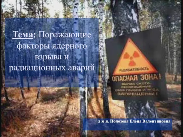 Поражающие факторы ядерного взрыва и радиационных аварий
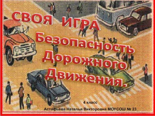 Своя игра. Безопасность движения
 Безопасность жизнедеятельности
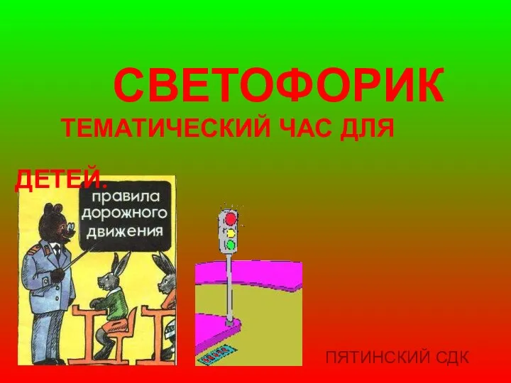 Светофорик приглашает. Тематический час для детей
 Виды светофоров
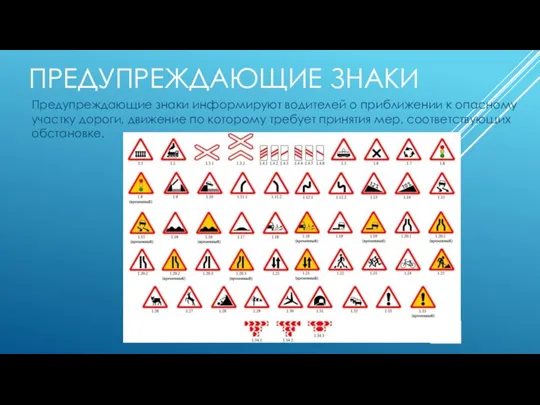 Предупреждающие знаки
 Зачем нужно мыть руки и чистить зубы
 Медико-психологические аспекты помощи при нарушениях психики у медицинских работников и спасателей в чрезвычайных ситуациях
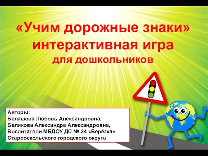 Игра Учим дорожные знаки для дошкольников
 Секреты здорового питания (мероприятие для учеников начальных классов)
 презентация Уголовная ответственность несовершеннолетних
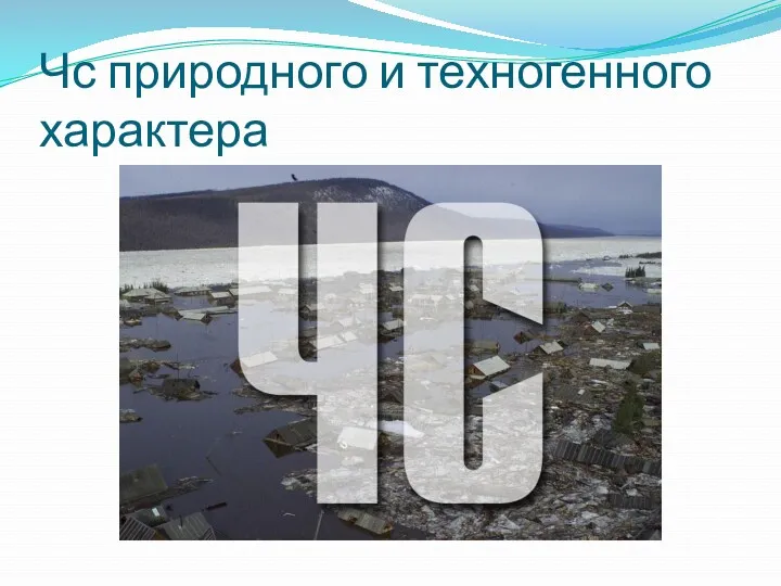 ЧС природного и техногенного характера
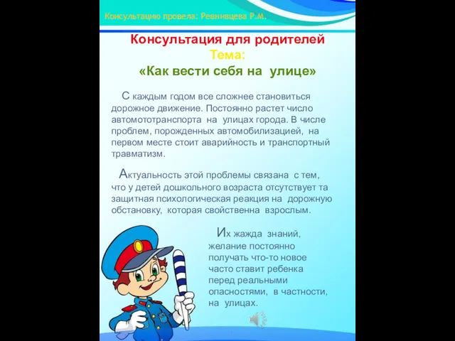 Консультация для родителей. Как вести себя на улице
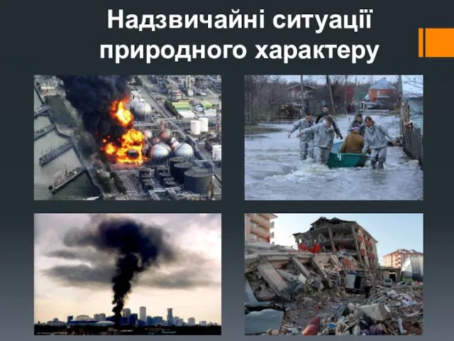 Надзвичайні ситуації природного характеру
 Заходи безпеки на залізничних коліях
 Эффекты радиационного воздействия
 Единая государственная система предупреждения и ликвидации чрезвычайных ситуаций (РСЧС)
 Личная безопасность гостей, работников гостиницы и их собственности. Концепция системы безопасности гостиницы
 Санитарно-гигиенические мероприятия при передвижении войск автомобильным транспортом
 Путешествие в страну Дорожных знаков
 Отравление аммиаком
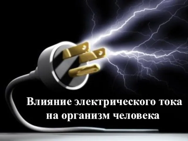 Влияние электрического тока на организм человека
 Классификация природных чрезвычайных ситуаций
 Презентация к уроку Радиация и жизнь
 Моя безопасность в условиях автономного пребывания в природной среды
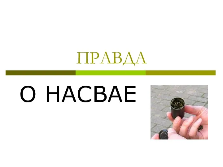 Правда о насвае
 Стратегия формирования здорового образа жизни обучающихся, как основной компонент валеологии