- Safety Fundamentals for NPPs

Содержание
- 2. Training Objectives Terminal Training Objectives: To list the safety systems used to carry out functions for
- 3. Content Safety fundamentals for NPPs Design and Safety Functions VVER Safety Systems A. Reactivity control B.
- 4. Safety Fundamentals for NPPs
- 5. Definition of «Safety» I. Safety is the state of being "safe" (from French sauf), the condition
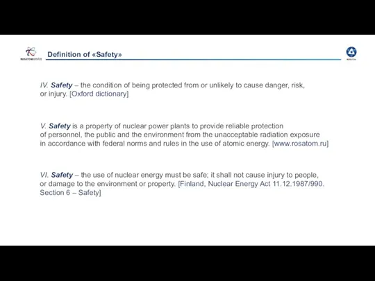
- 6. Definition of «Safety» IV. Safety – the condition of being protected from or unlikely to cause
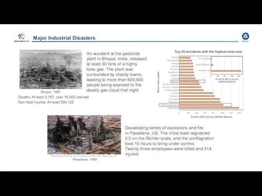
- 7. Major Industrial Disasters Devastating series of explosions and fire in Pasadena, US. The initial blast registered
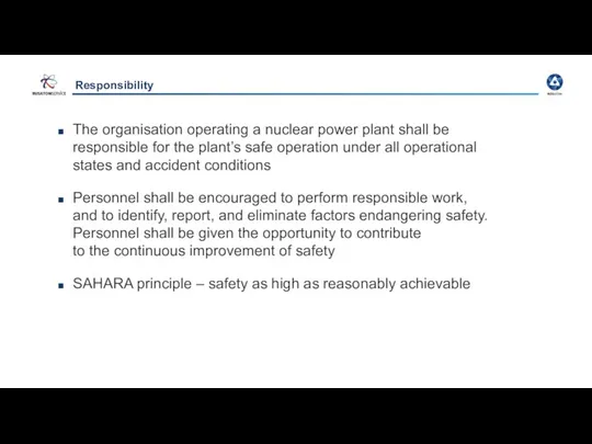
- 8. Responsibility The organisation operating a nuclear power plant shall be responsible for the plant’s safe operation
- 9. Design and Safety Functions
- 10. Prevention Control of anticipated operational occurrences Defense-in-Depth: Five Successive Levels of Protection Safety levels Control of
- 11. Physical barriers system Barrier 1 Barrier 2 Barrier 3 Barrier 4 Fuel pellet Fuel element cladding
- 12. DiD Principle Defense-in-depth is a philosophy to ensure nuclear safety
- 13. Design Basis Conditions (DBC) and Design Extension Conditions (DEC) In the deterministic safety analysis, as per
- 14. In accordance with Gov. Decree 717/2013 (and then YVL C.3) in case of accidents the expected
- 15. Plant Design Envelope Beyond Plant Design Envelope LEVEL 1 LEVEL 2 LEVEL 5 LEVELS OF DEFENCE
- 16. Fundamental Safety Functions Conditions Functions Operational plant states During and after any design basis accident In
- 17. VVER Safety Systems
- 18. DiD level 3 Level 3 is divided into levels 3a and 3b: Level 3a includes systems
- 19. Accident management Accident management strategy includes: bringing the NPP to the controlled state bringing the NPP
- 20. Safety Functions Basic safety functions
- 21. Design principles of safety systems Safety systems are designed in accordance with the principles ensuring their
- 22. General diagram of safety systems and means PHRS tank JNB Containment PHRS condenser Containment Pressurizer JEF
- 23. A. Reactivity control
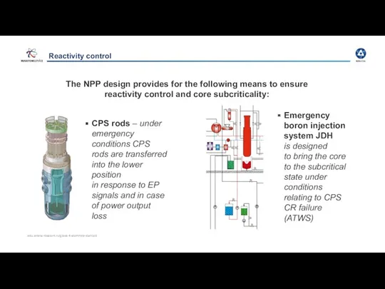
- 24. Reactivity control Emergency boron injection system JDH is designed to bring the core to the subcritical
- 25. Emergency Injection System Supplies boric acid solution with the concentration of 40 g/kg and temperature of
- 26. B. Heat removal from nuclear fuel
- 27. BA: Maintenance of primary coolant inventory The design provides for the following systems and means to
- 28. BB: Heat removal from primary coolant Means ensuring heat removal from the core and RP cooldown
- 29. System for passive heat removal through steam generators The system for passive heat removal through steam
- 30. BC and BD: Primary and secondary circuit integrity assurance Pressure is reduced in the primary circuit
- 31. Pressurizer relief devices The primary circuit overpressure protection system includes three pilot-operated relief valves, each consisting
- 32. BE: Spent fuel cooling The following systems are provided for in the design to remove heat
- 33. C. Localization of activity
- 34. CA: Limitation of pressure inside the containment, heat removal from the containment Pump KAA Pump JMN
- 35. Accident localization system Containment system: leak-proof steel liner reinforced concrete enclosing structures manholes, locks penetrations isolating
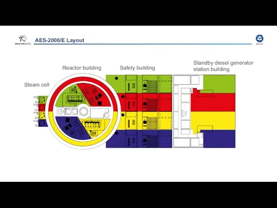
- 36. AES-2006/E Layout Steam cell Reactor building Safety building Standby diesel generator station building
- 38. Скачать презентацию
Training Objectives
Terminal Training Objectives:
To list the safety systems used to carry
Training Objectives
Terminal Training Objectives:
To list the safety systems used to carry
Content
Safety fundamentals for NPPs
Design and Safety Functions
VVER Safety Systems
A. Reactivity control
B.
Content
Safety fundamentals for NPPs
Design and Safety Functions
VVER Safety Systems
A. Reactivity control
B.
Safety Fundamentals for NPPs
Safety Fundamentals for NPPs
Definition of «Safety»
I. Safety is the state of being "safe"
Definition of «Safety»
I. Safety is the state of being "safe"
Definition of «Safety»
IV. Safety – the condition of being protected
Definition of «Safety»
IV. Safety – the condition of being protected
Major Industrial Disasters
Devastating series of explosions and fire
in Pasadena,
Major Industrial Disasters
Devastating series of explosions and fire in Pasadena,
Responsibility
The organisation operating a nuclear power plant shall be responsible for
Responsibility
The organisation operating a nuclear power plant shall be responsible for
Design and Safety Functions
Design and Safety Functions
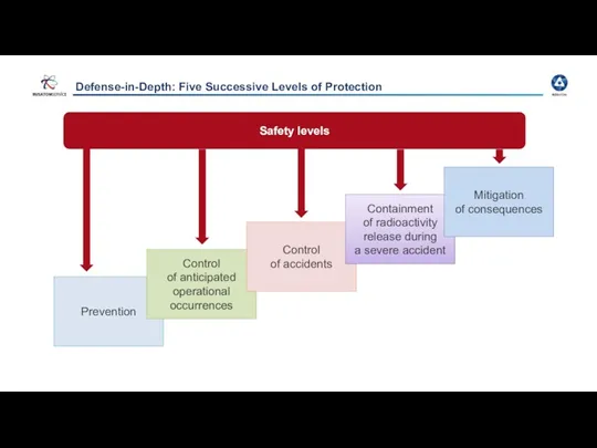
Prevention
Control
of anticipated operational occurrences
Defense-in-Depth: Five Successive Levels of Protection
Safety levels
Control
Prevention
Control
of anticipated operational occurrences
Defense-in-Depth: Five Successive Levels of Protection
Safety levels
Control
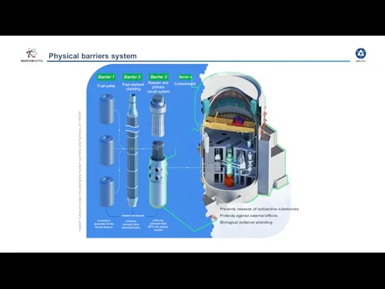
Physical barriers system
Barrier 1
Barrier 2
Barrier 3
Barrier 4
Fuel pellet
Fuel element cladding
Reactor and
Physical barriers system
Barrier 1
Barrier 2
Barrier 3
Barrier 4
Fuel pellet
Fuel element cladding
Reactor and
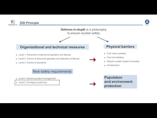
DiD Principle
Defense-in-depth is a philosophy
to ensure nuclear safety
DiD Principle
Defense-in-depth is a philosophy
to ensure nuclear safety
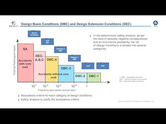
Design Basis Conditions (DBC) and Design Extension Conditions (DEC)
In the deterministic
Design Basis Conditions (DBC) and Design Extension Conditions (DEC)
In the deterministic
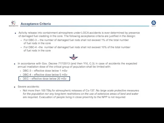
In accordance with Gov. Decree 717/2013 (and then YVL C.3) in
In accordance with Gov. Decree 717/2013 (and then YVL C.3) in
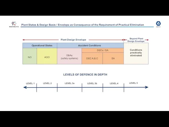
Plant Design Envelope
Beyond Plant Design Envelope
LEVEL 1
LEVEL 2
LEVEL 5
LEVELS OF DEFENCE
Plant Design Envelope
Beyond Plant Design Envelope
LEVEL 1
LEVEL 2
LEVEL 5
LEVELS OF DEFENCE
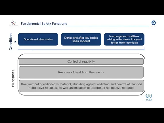
Fundamental Safety Functions
Conditions
Functions
Operational plant states
During and after any design basis
Fundamental Safety Functions
Conditions
Functions
Operational plant states
During and after any design basis
VVER Safety Systems
VVER Safety Systems
DiD level 3
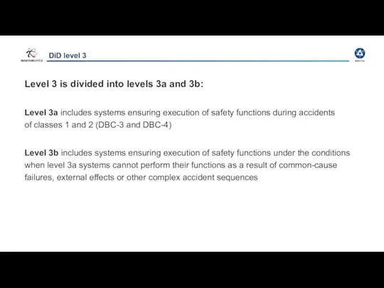
Level 3 is divided into levels 3a and 3b:
Level 3a includes systems
DiD level 3
Level 3 is divided into levels 3a and 3b:
Level 3a includes systems
Accident management
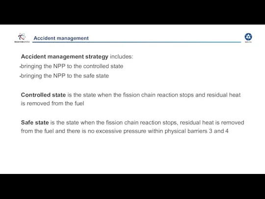
Accident management strategy includes:
bringing the NPP to the controlled state
bringing
Accident management
Accident management strategy includes:
bringing the NPP to the controlled state
bringing
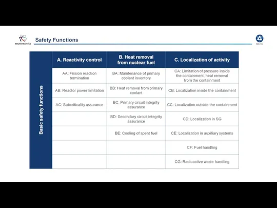
Safety Functions
Basic safety functions
Safety Functions
Basic safety functions
Design principles of safety systems
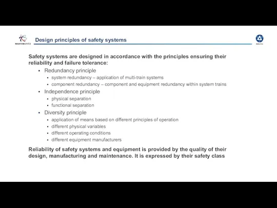
Safety systems are designed in accordance with
Design principles of safety systems
Safety systems are designed in accordance with
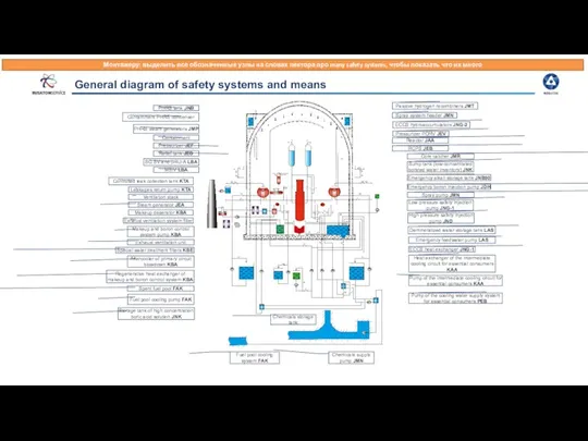
General diagram of safety systems and means
PHRS tank JNB
Containment PHRS condenser
General diagram of safety systems and means
PHRS tank JNB
Containment PHRS condenser
A. Reactivity control
A. Reactivity control
Reactivity control
Emergency boron injection system JDH
is designed
to bring the
Reactivity control
Emergency boron injection system JDH is designed to bring the
Emergency Injection System
Supplies boric acid solution with the concentration of 40 g/kg
Emergency Injection System
Supplies boric acid solution with the concentration of 40 g/kg
B. Heat removal from nuclear fuel
B. Heat removal from nuclear fuel
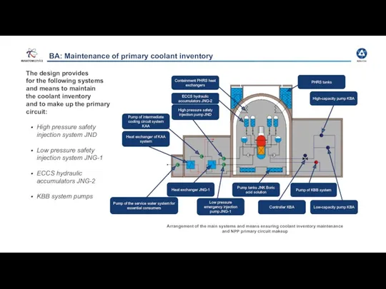
BA: Maintenance of primary coolant inventory
The design provides
for the following
BA: Maintenance of primary coolant inventory
The design provides for the following
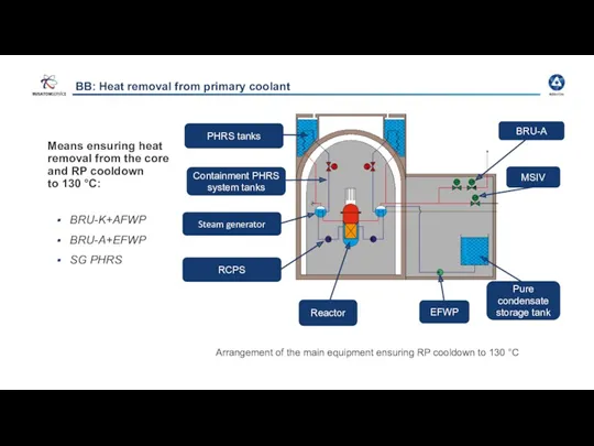
BB: Heat removal from primary coolant
Means ensuring heat removal from
BB: Heat removal from primary coolant
Means ensuring heat removal from
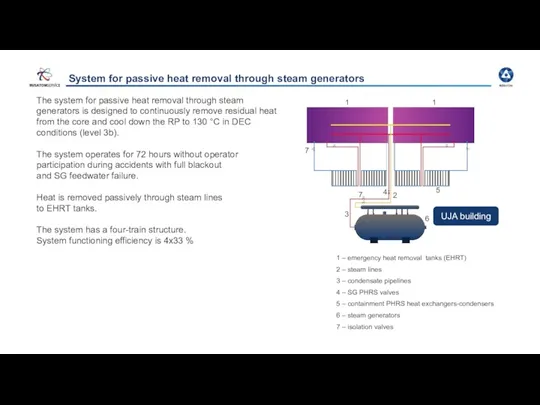
System for passive heat removal through steam generators
The system for passive
System for passive heat removal through steam generators
The system for passive
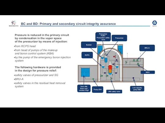
BC and BD: Primary and secondary circuit integrity assurance
Pressure is reduced
BC and BD: Primary and secondary circuit integrity assurance
Pressure is reduced
Pressurizer relief devices
The primary circuit overpressure protection system includes three pilot-operated
Pressurizer relief devices
The primary circuit overpressure protection system includes three pilot-operated
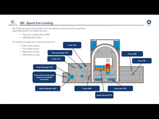
BE: Spent fuel cooling
The following systems are provided for in the
BE: Spent fuel cooling
The following systems are provided for in the
C. Localization of activity
C. Localization of activity
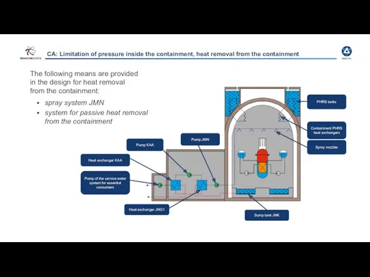
CA: Limitation of pressure inside the containment, heat removal from the
CA: Limitation of pressure inside the containment, heat removal from the
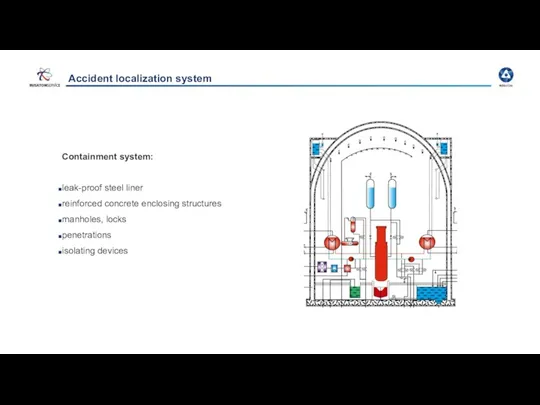
Accident localization system
Containment system:
leak-proof steel liner
reinforced concrete enclosing structures
manholes, locks
penetrations
isolating devices
Accident localization system
Containment system:
leak-proof steel liner
reinforced concrete enclosing structures
manholes, locks
penetrations
isolating devices
AES-2006/E Layout
Steam cell
Reactor building
Safety building
Standby diesel generator station building
AES-2006/E Layout
Steam cell
Reactor building
Safety building
Standby diesel generator station building
 Четыре шага к респираторной защите
 Система оповещения населения о чрезвычайных ситуациях
 Почему нужно чистить зубы и мыть руки
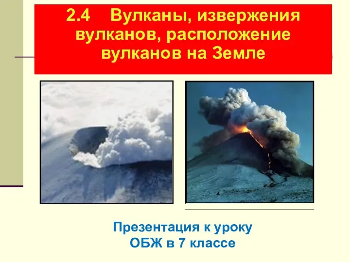 Вулканы, извержения вулканов, расположение вулканов на Земле. Урок ОБЖ в 7 классе
 Пожары
 Предписывающие знаки. Вопросы
 Отравления угарным газом
 Вимоги безпеки при експлуатації технологічних систем під тиском
 Пожарная безопасность
 Профілактика ВІЛ-інфекції/ СНІДу
 Терроризм - угроза для человечества
 Средства защиты от электрического тока
 Лето красное-безопасное. Формирование у детей выполнения правил поведения, обеспечивающих сохранность их жизни и здоровья
 Метрологиялық қызметінің тексеру бөлімшелері және өндірістік құрылғыларға
 Мероприятия медицинской службы в очагах химических и радиационных поражений
 Радиационно, химически и биологически опасные объекты
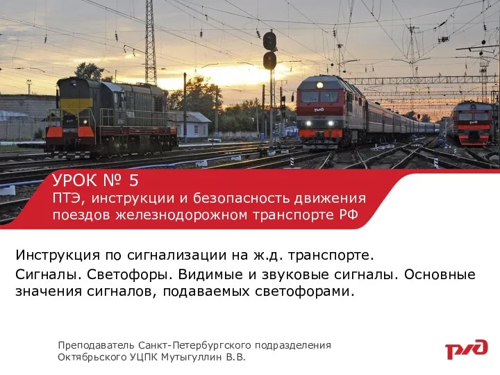 ПТЭ, инструкции и безопасность движения поездов железнодорожном транспорте РФ. Урок № 5
 чрезвычайные ситуации техногенного характера
 Безопасность на предприятиях общественного питания
 Влияние алкоголя и табака на здоровье человека
 Фізичні наслідки статевого життя до шлюбу
 презентация к уроку
 Дорожно-транспортные проишествия
 Чрезвычайные ситуации и их классификация
 Правовое регулирование аварийно-восстановительных работ
 Общие вопросы организации охраны труда
 Азбука безопасности на улице и дома для дошкольников
 Анализ травматизма по ПАО МРСК Северо-Запада за 2018