- A5 series debug guide

Содержание
- 2. CHIP RESISTOR
- 3. DIODE P N
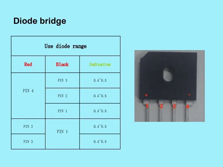
- 4. Diode bridge
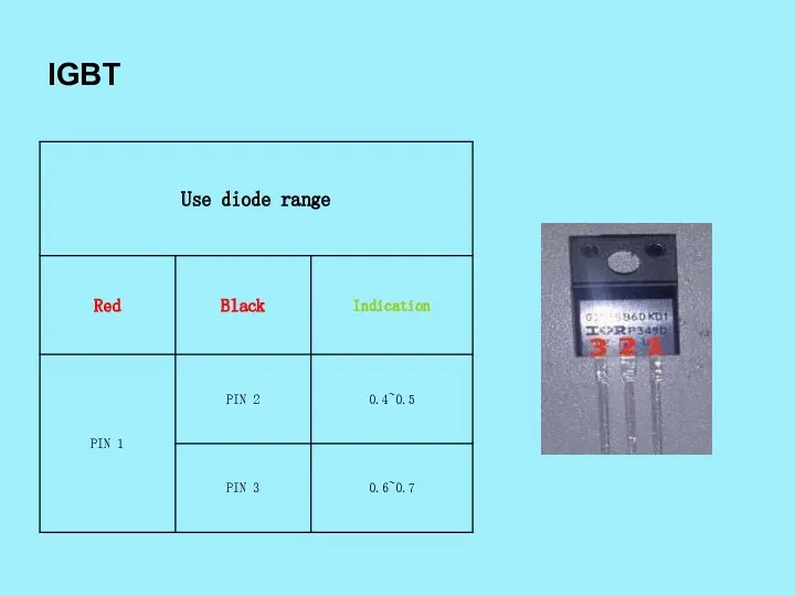
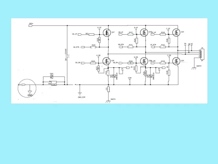
- 5. IGBT
- 6. IRF530
- 7. IC (2272) mark
- 8. 32V 5V 15V 5V Rectifier /filter Device module DC switch power supply motor MAIN IC trimming
- 9. AHE58
- 10. POWER SUPPLY BLOCK rectifier/filter AC 220V DC 300V Switch Power Supply To control IC DC 15V
- 11. Device Module Block J2 Encoder signal Main IC U2 Motor angel signal HALL signal UP position
- 12. SOLENOID CIRCUIT Master Chip U2 U7 U8 U29 U3 U4 U23 Q6 Q1 Q7 Q8 U27
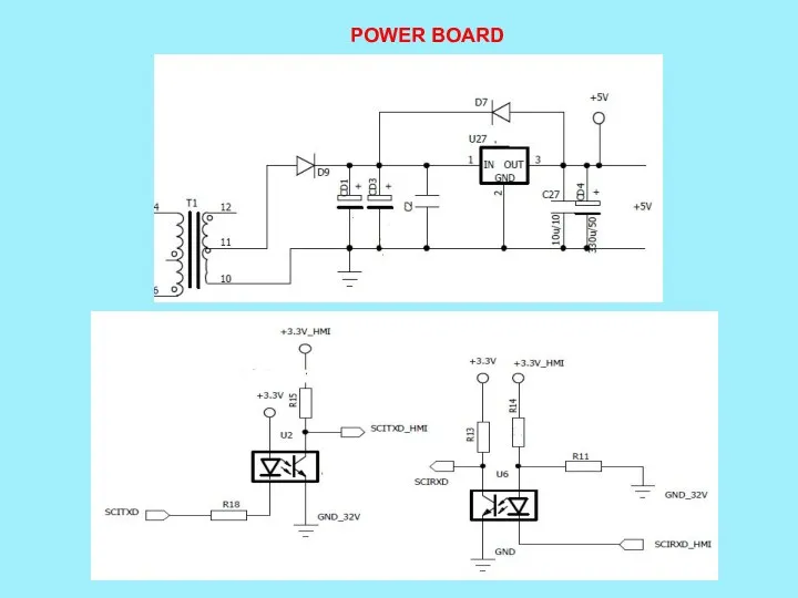
- 13. POWER BOARD Solenoid control footlift Thread tension Back tacking wiping Trimm ing DC power supply 5V
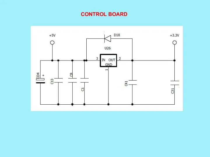
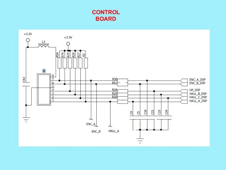
- 14. Control Board MIAN IC Rectifier /filter Device Control 3.3V
- 15. Power Board Control Board
- 16. Err-01 Test Test Test Test Test
- 17. Power board Control board C9 C8 U10 2136 IGBT
- 18. Control board
- 19. Control board
- 20. Err-07 Test Test
- 21. 2272
- 22. Control board
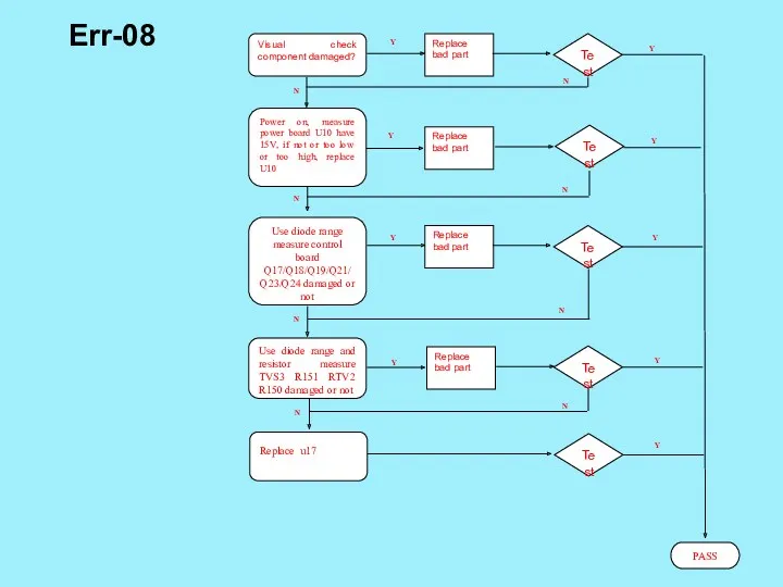
- 23. Err-08 Test Test Test Test
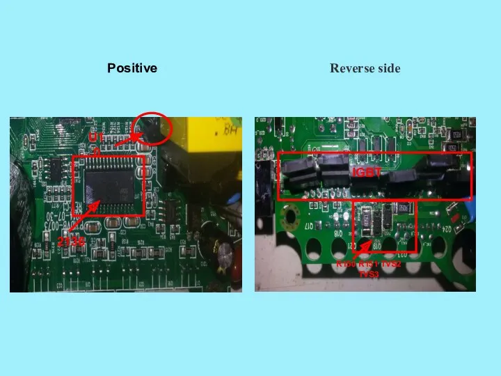
- 24. Power board Control board U10 2136 IGBT
- 25. Control board
- 26. Control board
- 27. Err-09 Test Test Test
- 28. IGBT
- 29. Power Supply
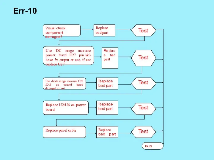
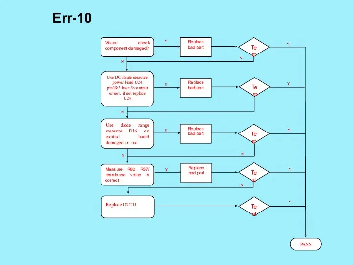
- 30. Err-10 Test Test Test Test Test
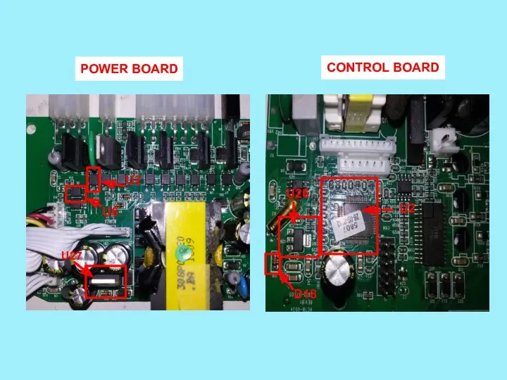
- 31. U27 D18 U26 U2 POWER BOARD CONTROL BOARD U6 U2 U27
- 32. POWER BOARD
- 33. CONTROL BOARD
- 34. Err-13 Test Test Test
- 35. CONTROL BOARD
- 36. CONTROL BOARD
- 37. AHE59
- 38. Replace bad part Visual check component damaged? Test Replace bad part Test PASS Y Y N
- 39. Reverse side IGBT R150 R151 TVS2 TVS3 Positive U10 2136
- 42. Replace bad part Visual check component damaged? Test Replace bad part Test PASS Y Y N
- 43. Reverse side IGBT R150 R151 TVS2 TVS3 Positive U10 2136
- 46. Replace bad part Visual check component damaged? Test Replace bad part Test PASS Y Use DC
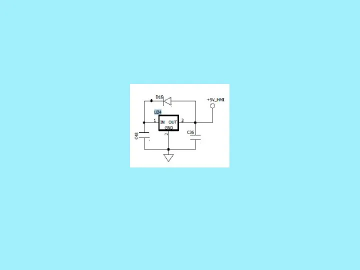
- 47. Reverse side U24 D16 Positive 1
- 50. Скачать презентацию
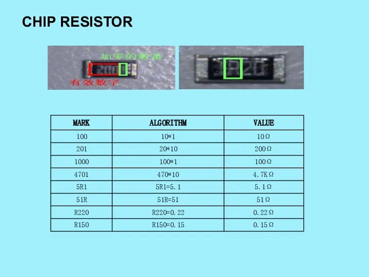
CHIP RESISTOR
CHIP RESISTOR
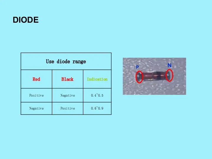
DIODE
P
N
DIODE
P
N
Diode bridge
Diode bridge
IGBT
IGBT
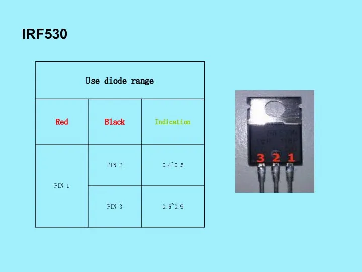
IRF530
IRF530
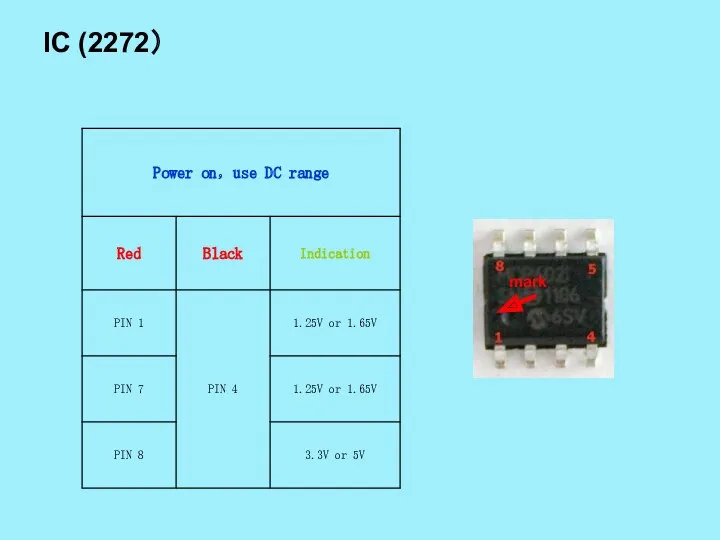
IC (2272)
mark
IC (2272)
mark
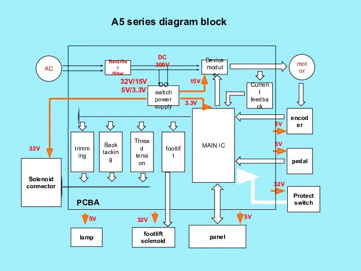
32V
5V
15V
5V
Rectifier
/filter
Device
module
DC switch power supply
motor
MAIN IC
trimming
Back tacking
footlift
Thread tension
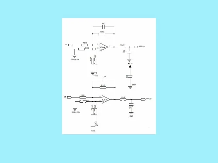
Current feedback
AC
encoder
pedal
footlift solenoid
Protect switch
DC 300V
32V/15V
32V
5V
15V
5V
Rectifier
/filter
Device
module
DC switch power supply
motor
MAIN IC
trimming
Back tacking
footlift
Thread tension
Current feedback
AC
encoder
pedal
footlift solenoid
Protect switch
DC 300V
32V/15V
AHE58
AHE58
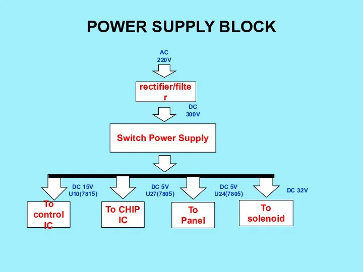
POWER SUPPLY BLOCK
rectifier/filter
AC 220V
DC 300V
Switch Power Supply
To control IC
DC 15V U10(7815)
To
POWER SUPPLY BLOCK
rectifier/filter
AC 220V
DC 300V
Switch Power Supply
To control IC
DC 15V U10(7815)
To
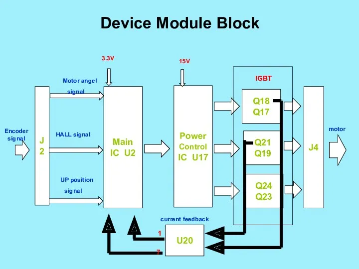
Device Module Block
J2
Encoder signal
Main IC U2
Motor angel signal
HALL signal
Device Module Block
J2
Encoder signal
Main IC U2
Motor angel signal
HALL signal
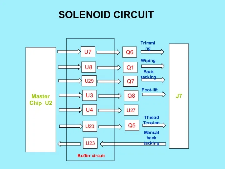
SOLENOID CIRCUIT
Master Chip U2
U7
U8
U29
U3
U4
U23
Q6
Q1
Q7
Q8
U27
U23
Q5
J7
Trimming
Wiping
Back tacking
Foot-lift
Thread Tension
Manual back tacking
Buffer circuit
SOLENOID CIRCUIT
Master Chip U2
U7
U8
U29
U3
U4
U23
Q6
Q1
Q7
Q8
U27
U23
Q5
J7
Trimming
Wiping
Back tacking
Foot-lift
Thread Tension
Manual back tacking
Buffer circuit
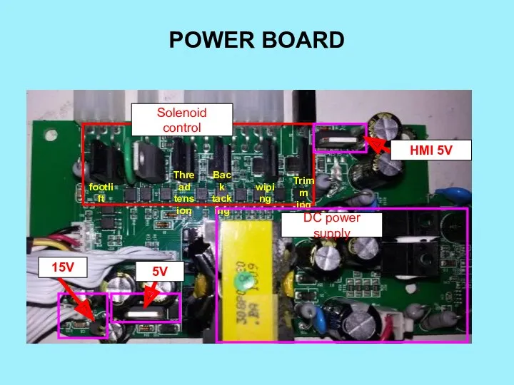
POWER BOARD
Solenoid control
footlift
Thread
tension
Back
tacking
wiping
Trimm
ing
DC power supply
5V
15V
HMI 5V
POWER BOARD
Solenoid control
footlift
Thread
tension
Back
tacking
wiping
Trimm
ing
DC power supply
5V
15V
HMI 5V
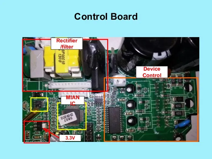
Control Board
MIAN IC
Rectifier
/filter
Device
Control
3.3V
Control Board
MIAN IC
Rectifier
/filter
Device
Control
3.3V
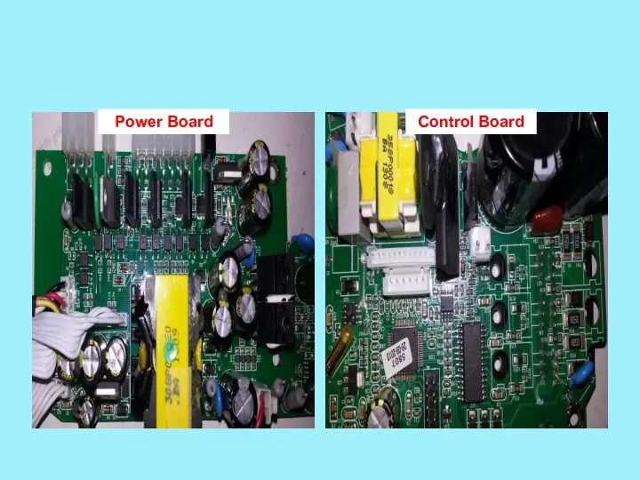
Power Board
Control Board
Power Board
Control Board
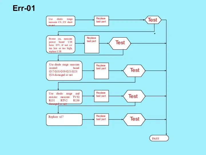
Err-01
Test
Test
Test
Test
Test
Err-01
Test
Test
Test
Test
Test
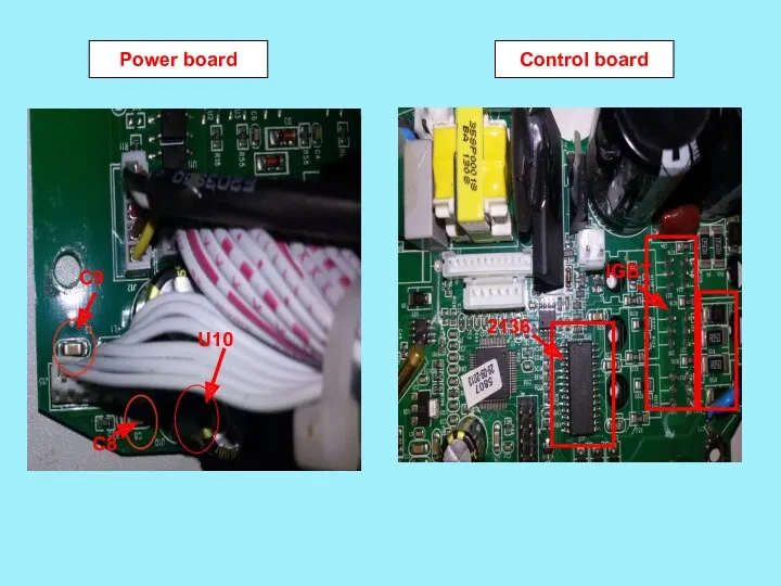
Power board
Control board
C9
C8
U10
2136
IGBT
Power board
Control board
C9
C8
U10
2136
IGBT

Control board
Control board
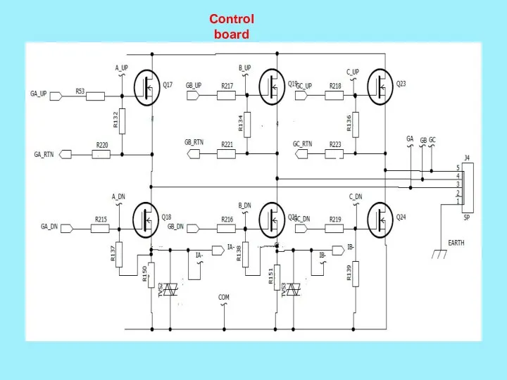
Control board
Control board
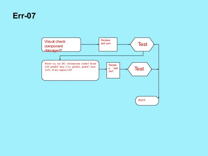
Err-07
Test
Test
Err-07
Test
Test
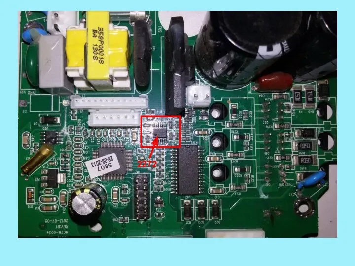
2272
2272
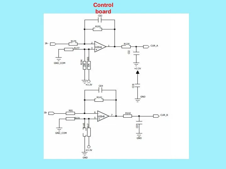
Control board
Control board
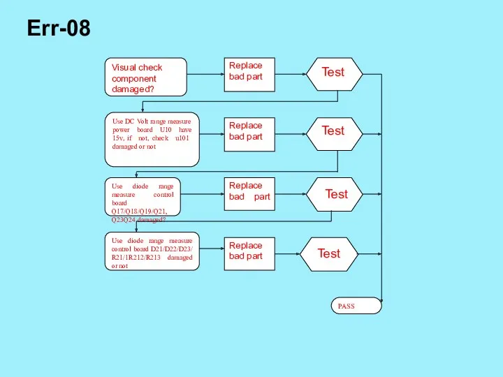
Err-08
Test
Test
Test
Test
Err-08
Test
Test
Test
Test
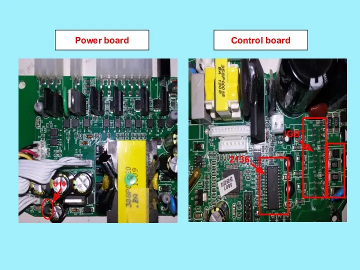
Power board
Control board
U10
2136
IGBT
Power board
Control board
U10
2136
IGBT
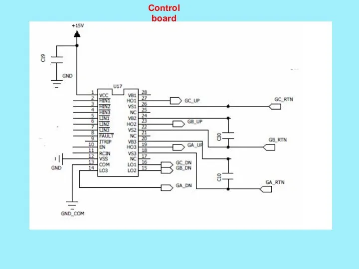
Control board
Control board

Control board
Control board
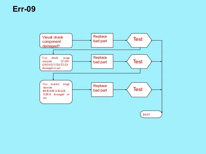
Err-09
Test
Test
Test
Err-09
Test
Test
Test
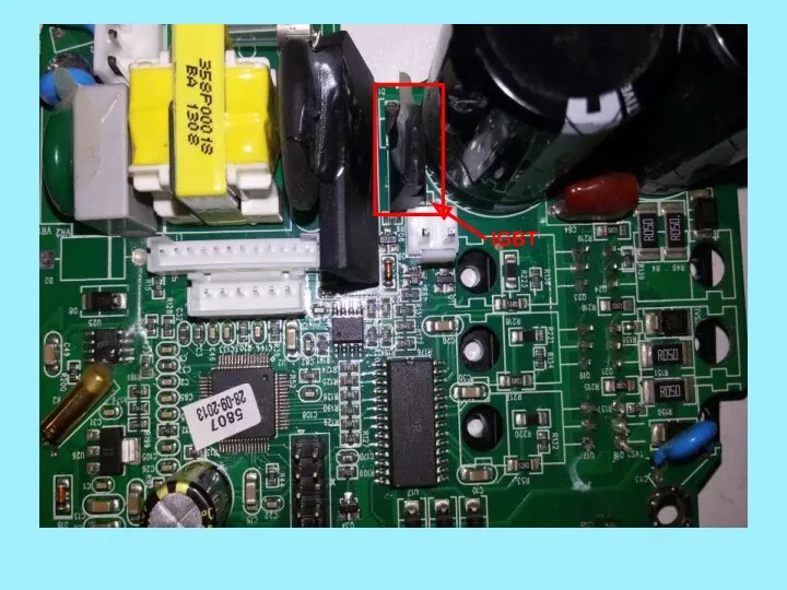
IGBT
IGBT
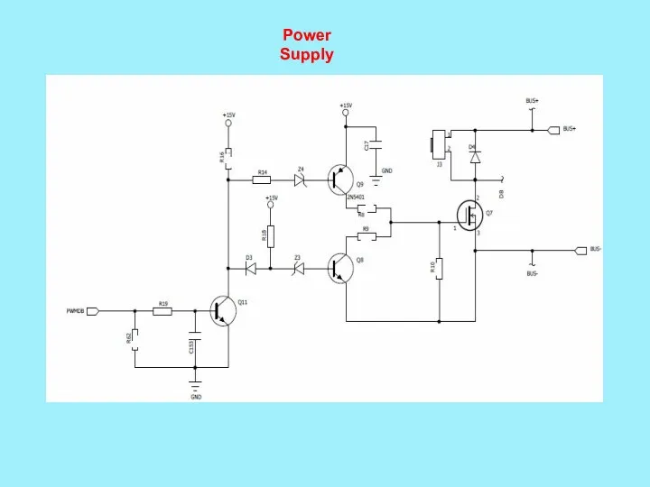
Power Supply
Power Supply
Err-10
Test
Test
Test
Test
Test
Err-10
Test
Test
Test
Test
Test
U27
D18
U26
U2
POWER BOARD
CONTROL BOARD
U6
U2
U27
U27
D18
U26
U2
POWER BOARD
CONTROL BOARD
U6
U2
U27
POWER BOARD
POWER BOARD
CONTROL BOARD
CONTROL BOARD
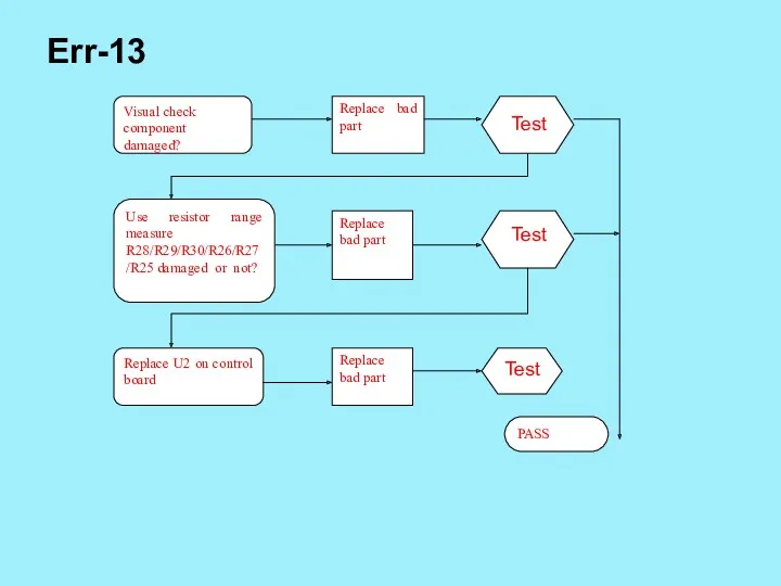
Err-13
Test
Test
Test
Err-13
Test
Test
Test
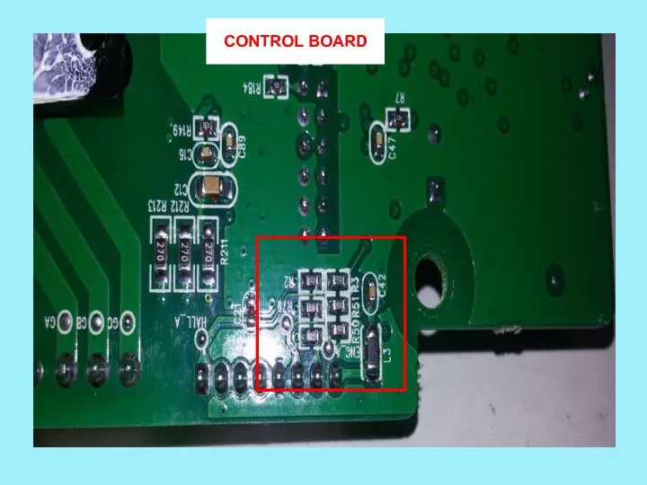
CONTROL BOARD
CONTROL BOARD
CONTROL BOARD
CONTROL BOARD

AHE59
AHE59
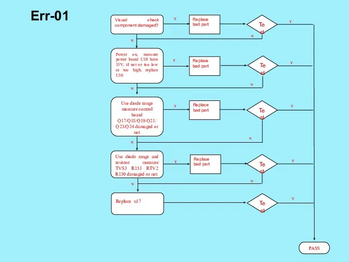
Replace bad part
Visual check component damaged?
Test
Replace bad part
Test
PASS
Y
Y
N
Power on, measure power
Replace bad part
Visual check component damaged?
Test
Replace bad part
Test
PASS
Y
Y
N
Power on, measure power

Reverse side
IGBT
R150 R151 TVS2 TVS3
Positive
U10
2136
Reverse side
IGBT
R150 R151 TVS2 TVS3
Positive
U10
2136
Replace bad part
Visual check component damaged?
Test
Replace bad part
Test
PASS
Y
Y
N
Power on, measure power
Replace bad part
Visual check component damaged?
Test
Replace bad part
Test
PASS
Y
Y
N
Power on, measure power
Reverse side
IGBT
R150 R151 TVS2 TVS3
Positive
U10
2136
Reverse side
IGBT
R150 R151 TVS2 TVS3
Positive
U10
2136


Replace bad part
Visual check component damaged?
Test
Replace bad part
Test
PASS
Y
Use DC range measure
Replace bad part
Visual check component damaged?
Test
Replace bad part
Test
PASS
Y
Use DC range measure
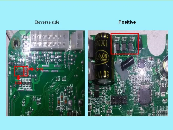
Reverse side
U24
D16
Positive
1
Reverse side
U24
D16
Positive
1
 Этика и деонтология в онкологии
 Что нужно знать о туберкулезе для личной безопасности?
 Презентация к занятию Чайный сервиз
 Места обитания, классификация зайцев
 Мои увлечения Мои наряды , мой стиль.
 Организация хранения и транспортировки ЛС, ИМН и медицинской техники
 Презентация Круг семейного чтения
 Урок Простые вещества - металлы
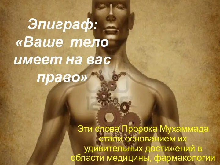 Ваше тело имеет на вас право
 Творчество Мариуса Ивановича Петипа
 Предмет и содержание курса медицинского снабжения Вооружённых Сил РК
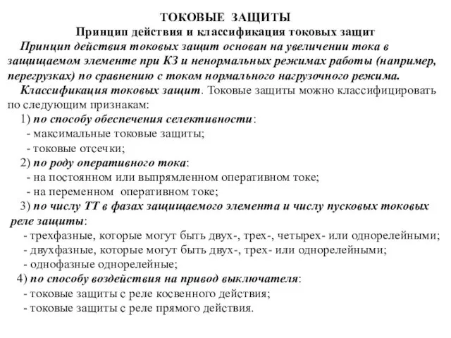 Токовые защиты. Принцип действия и классификация токовых защит
 Классный час Композиторы Кубани
 Теории происхождения нефти и газа – основа прогнозирования перспектив нефтеносности недр
 Решение неравенств, содержащих переменную под знаком модуля
 Микроклимат палатки
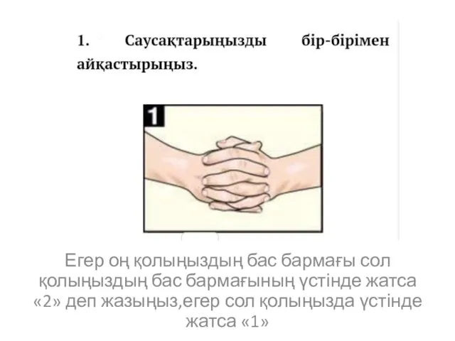 Саусақтарыңызды бір-бірімен айқастырыңыз
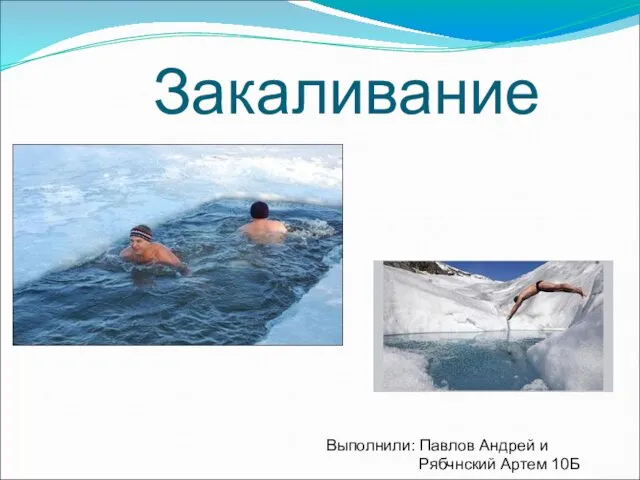 Закаливание. Методы закаливания
 Шаблон для презентаций Ко Дню Победы зеленый
 Православная позиция
 Использование оффшоров в международном менеджменте
 Подставка для яйца на Пасху (зайка) Диск
 Нанотехнологии - технологии будущего
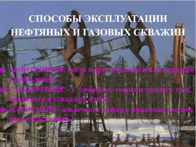 Способы эксплуатации нефтяных и газовых скважин
 Агрессия как социально-психологический феномен
 Символизм. Основные темы символистов
 OZoWS_GZUQaNOQ1uP_qq2A (1)
 Народные промыслы - Городецкая роспись