- CV338H-U42-10 maintainance guide

Содержание
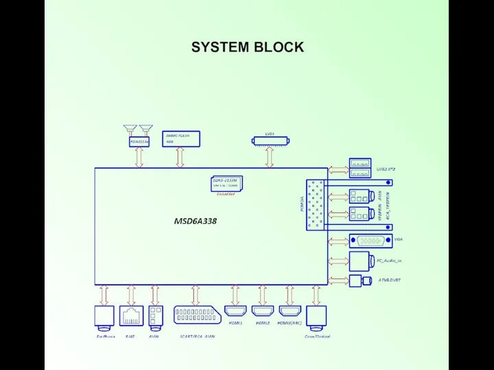
- 2. SYSTEM BLOCK
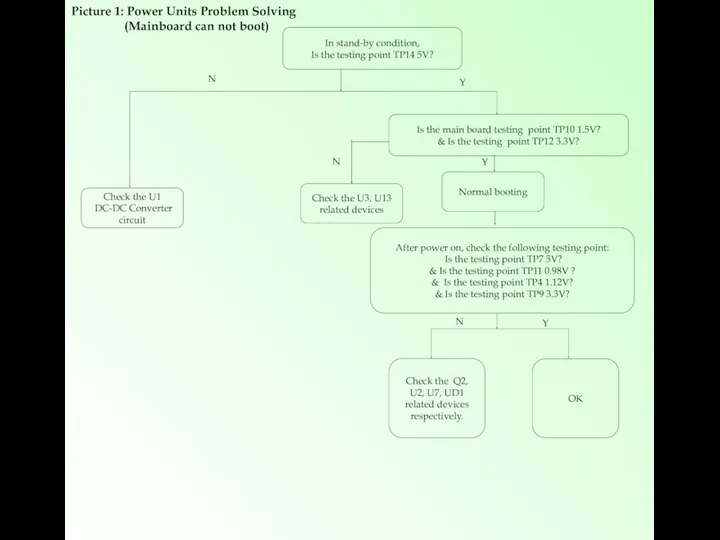
- 3. In stand-by condition, Is the testing point TP14 5V? Normal booting Check the Q2, U2, U7,
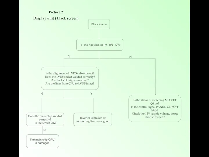
- 4. Black screen Is the testing point TP8 12V? Is the alignment of LVDS cable correct? Does
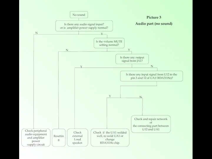
- 5. No sound Is there any audio signal input? or is amplifier power supply normal? Check peripheral
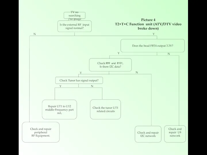
- 6. TV no searching /no image Picture 4 T2+T+C Function unit (ATV/DTV video broke down) Is the
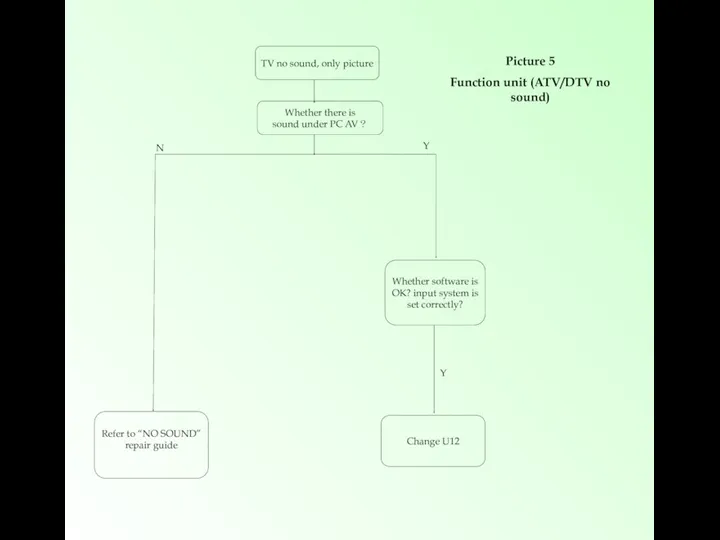
- 7. TV no sound, only picture Whether there is sound under PC AV? N Y Refer to
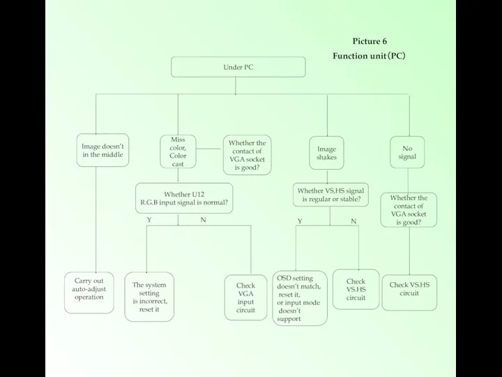
- 8. Under PC Image doesn’t in the middle Miss color, Color cast Image shakes No signal Carry
- 10. Скачать презентацию
SYSTEM BLOCK
SYSTEM BLOCK
In stand-by condition,
Is the testing point TP14 5V?
Normal booting
Check the Q2, U2, U7,
In stand-by condition,
Is the testing point TP14 5V?
Normal booting
Check the Q2, U2, U7,
Black screen
Is the testing point TP8 12V?
Is the alignment of LVDS cable correct?
Does
Black screen
Is the testing point TP8 12V?
Is the alignment of LVDS cable correct?
Does
No sound
Is there any audio signal input?
or is amplifier power supply normal?
Check peripheral
No sound
Is there any audio signal input?
or is amplifier power supply normal?
Check peripheral
TV no searching
/no image
Picture 4
T2+T+C Function unit (ATV/DTV video broke down)
Is the external
TV no searching
/no image
Picture 4
T2+T+C Function unit (ATV/DTV video broke down)
Is the external
TV no sound, only picture
Whether there is
sound under PC AV?
N
Y
Refer to “NO
TV no sound, only picture
Whether there is
sound under PC AV?
N
Y
Refer to “NO
Under PC
Image doesn’t
in the middle
Miss color,
Color
cast
Image
shakes
No signal
Carry out
auto-adjust
operation
Whether
Under PC
Image doesn’t
in the middle
Miss color,
Color
cast
Image
shakes
No signal
Carry out
auto-adjust
operation
Whether
 Будущая женщина, или Как правильно воспитывать девочку (консультация для родителей)
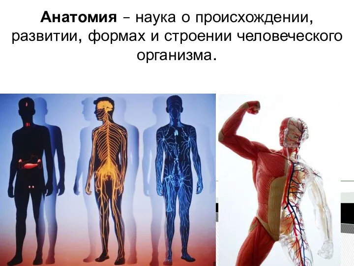 Анатомия – наука о происхождении, развитии, формах и строении человеческого организма
 Методология, теория и методы психологических исследований
 Культура Руси IX-XII веков
 Презентация Чудесный танец Вальс
 Определение суточного рациона питания по энергетической ценности пищевых продуктов
 Радиобиология человека
 Проект Моя семья
 20231119_urok_-_viktorina_gigiena_i_zdorove
 Роботы пылесосы
 Театрализованная деятельность в ДОУ
 Выявление дефектов возникающих в перегородках зданий
 Песни военных лет
 Презентация к классному часу Горячее сердце 2014
 Крупнейшие международные сети PR-агентств
 Презентация к уроку в рамках проекта Будь здоров!
 Внутрилабораторный контроль качества лабораторных исследований в УЗ
 Числа от 10 до 20
 Презентация урока природоведения 5 кл. Вещества, вырабатываемые растениями
 Презентация проекта педагогической деятельности Неделя здоровья
 Классификация мебели
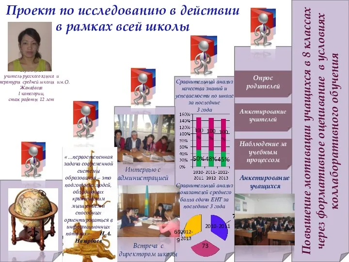 Проект по исследованию в действии в рамках всей школы
 My favorite actor
 ПЕТЕНКО ІА
 Презентация Народная свадебная кукла
 Вред употребления: снюс, насвай
 Синдром больного здания. Характеристика плюсов и минусов газификации жилого фонда
 Основы передачи данных в сетях. Лекция 3