- Development 3 Group Lab 1 (VD)

Содержание
- 2. Contents Product Overview Circuit Description Assembly and Disassembly Troubleshooting How to Execute Code Etc.
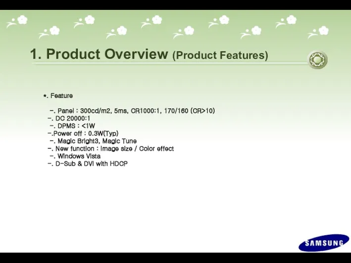
- 3. 1. Product Overview (Product Features) *. Feature -. Panel : 300cd/m2, 5ms, CR1000:1, 170/160 (CR>10) -.
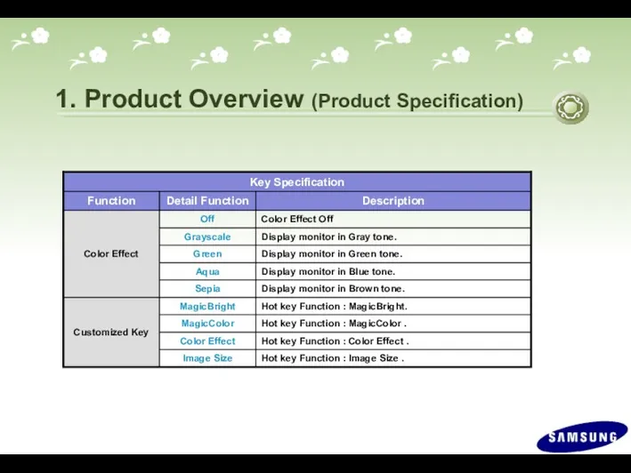
- 4. 1. Product Overview (Product Specification)
- 5. 1. Product Overview (Product Specification)
- 6. 1. Product Overview (Product Specification)
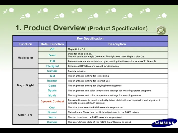
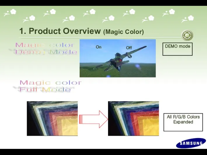
- 7. Magic color Demo Mode On Off Magic color Full Mode 1. Product Overview (Magic Color) All
- 8. Magic color Intelligent Mode 1. Product Overview (Magic Color) Except Skin Tone
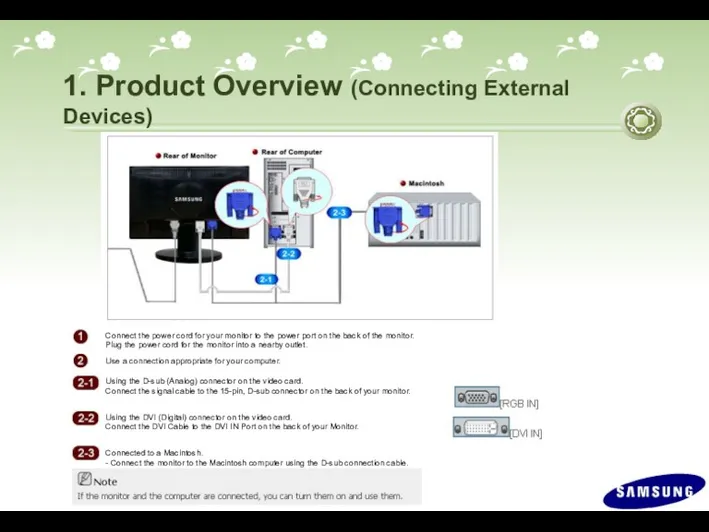
- 9. 1. Product Overview (Connecting External Devices)
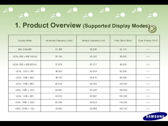
- 10. 1. Product Overview (Supported Display Modes)
- 11. 1. Product Overview (OSD Functions) MENU MagicBright™ / Down Brightness / Up Button Enter / Source
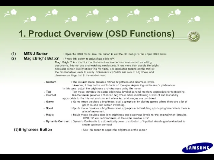
- 12. 1. Product Overview (OSD Functions) MENU Button : Open the OSD menu. Use this button to
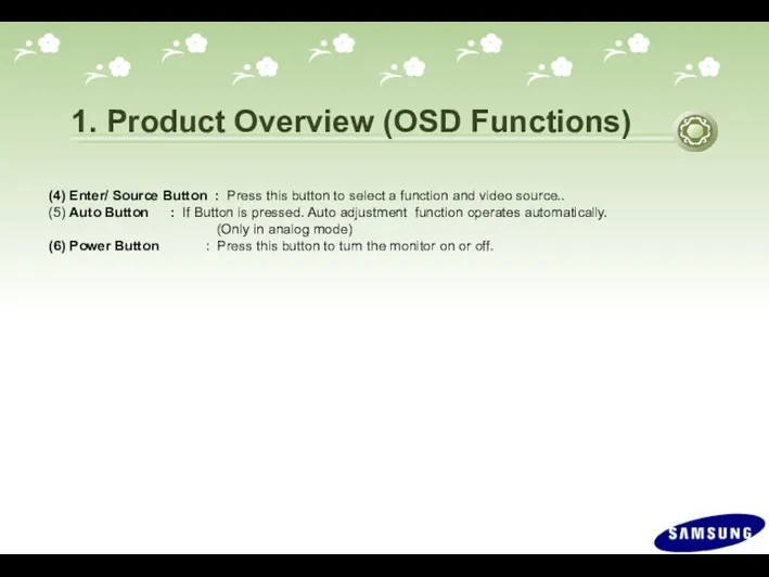
- 13. 1. Product Overview (OSD Functions) (4) Enter/ Source Button : Press this button to select a
- 14. 1. Product Overview (OSD Tree)
- 15. 1. Product Overview (OSD Hidden Key)
- 16. 1. Product Overview (Specifications of Options)
- 17. 2. Circuit Description (New Part) *. Scaler(MSTR) 2343BW (SE85AMH) / 2343NW(SE81AM) Use a type of scaler
- 18. 2. Circuit Description (Product Structure) 1. Panel Part See Product Specifications. 2. Main Board Part Receives
- 19. 2. Circuit Description (Panel Part)
- 20. 2. Circuit Description (Panel Part) * PROTECTION* LAMP(Inverter) PROTECION => The protection is activated if there
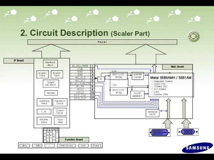
- 21. 2. Circuit Description (Scaler Part) P a n e l 5V Mstar SE85AMH / SE81AM -.
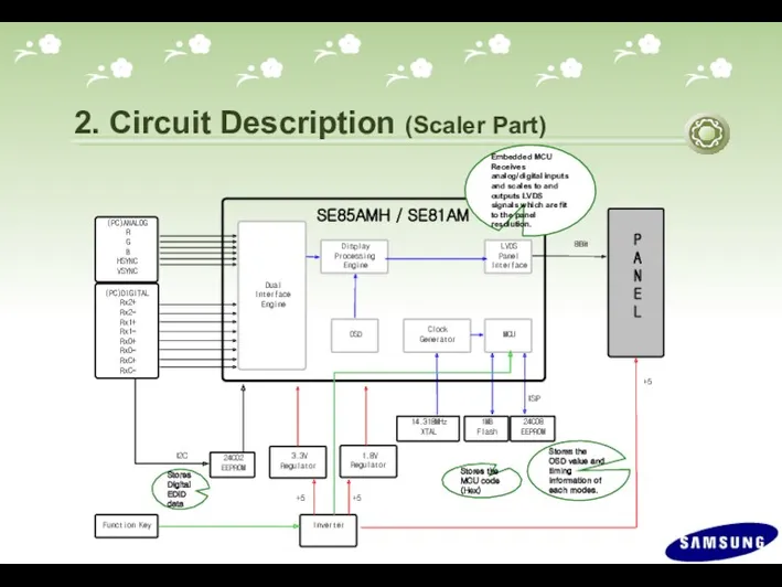
- 22. 2. Circuit Description (Scaler Part) P A N E L 24C08 EEPROM 1MB Flash Dual Interface
- 23. 2. Circuit Description (Power Flow Chart) IC 601 (NCP1117ST33T3G) IC 602 (NCP1117DT1815G) IC 203 (AT24C08) IC
- 24. 2. Circuit Description (Circuit Diagram)
- 25. 2. Circuit Description (Main PBA)
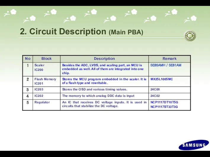
- 26. 2. Circuit Description (Main PBA)
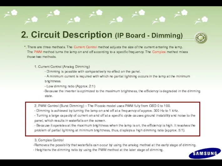
- 27. 2. Circuit Description (IP Board - Dimming) *. There are three methods. The Current Control method
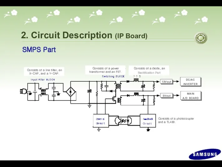
- 28. 2. Circuit Description (IP Board) SMPS Part Consists of a line filter, an X-CAP, and a
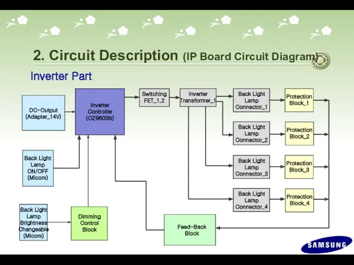
- 29. 2. Circuit Description (IP Board Circuit Diagram) Inverter Part DC-Output (Adapter_14V) Dimming Control Block Back Light
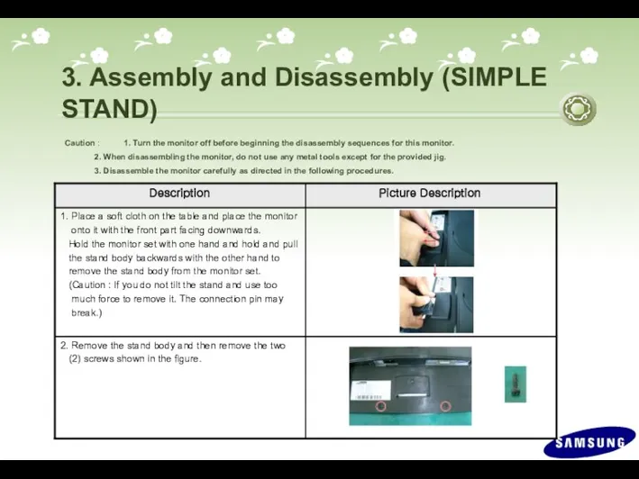
- 30. 3. Assembly and Disassembly (SIMPLE STAND) Caution : 1. Turn the monitor off before beginning the
- 31. 3. Assembly and Disassembly
- 32. 3. Assembly and Disassembly
- 33. 3. Assembly and Disassembly
- 34. 3. Assembly and Disassembly ※ The assembly is in the reverse order of disassembly
- 35. 3. Assembly and Disassembly (HAS STAND) ※ The assembly is in the reverse order of disassembly
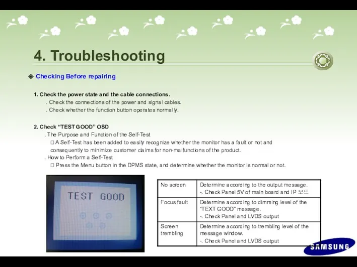
- 36. 4. Troubleshooting Checking Before repairing 1. Check the power state and the cable connections. . Check
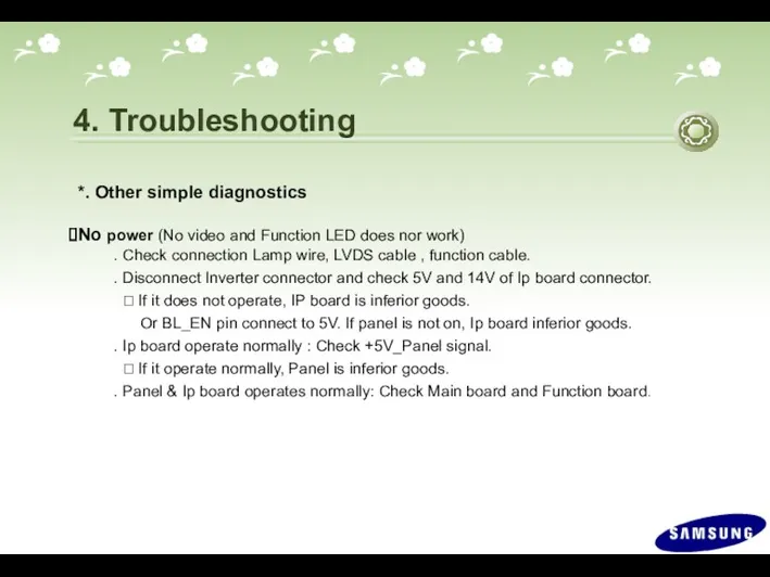
- 37. 4. Troubleshooting *. Other simple diagnostics No power (No video and Function LED does nor work)
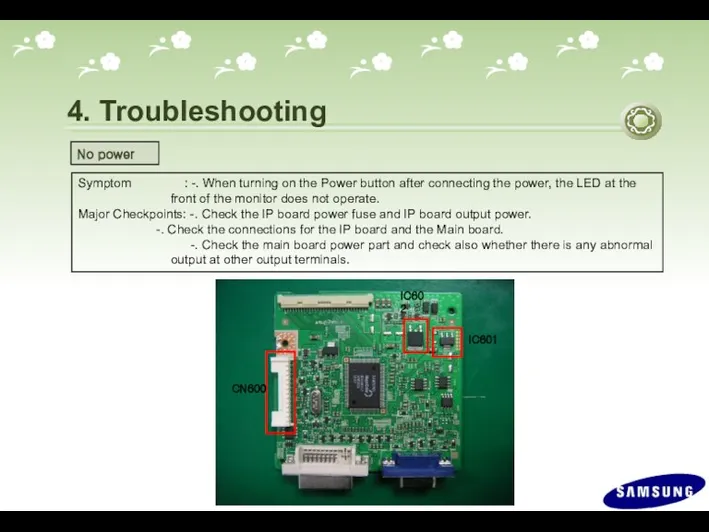
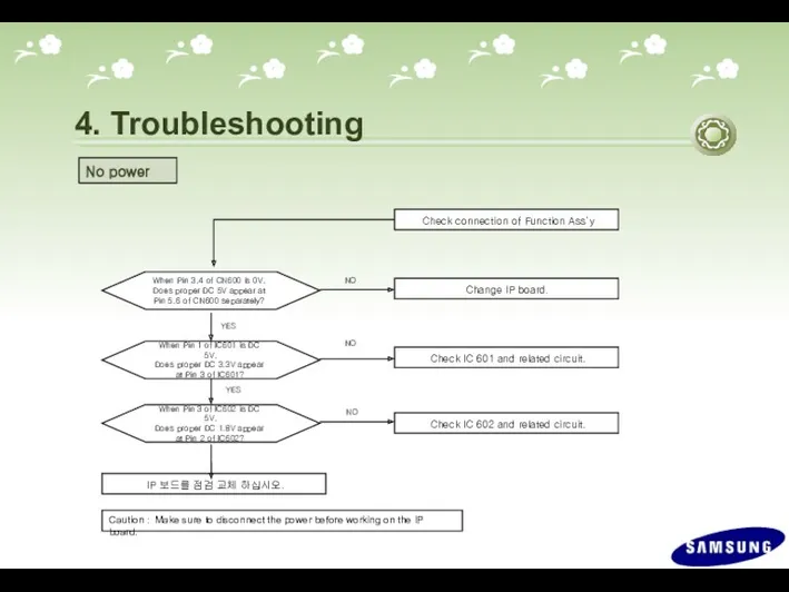
- 38. 4. Troubleshooting Symptom : -. When turning on the Power button after connecting the power, the
- 39. 4. Troubleshooting No power Check IC 601 and related circuit. Check IC 602 and related circuit.
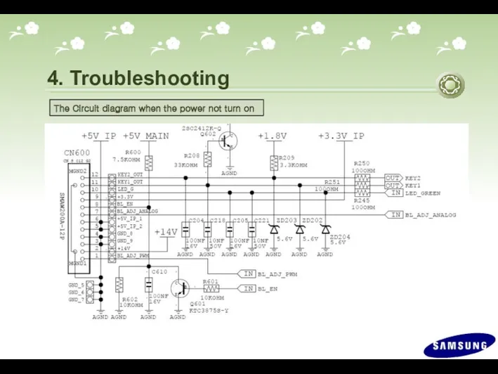
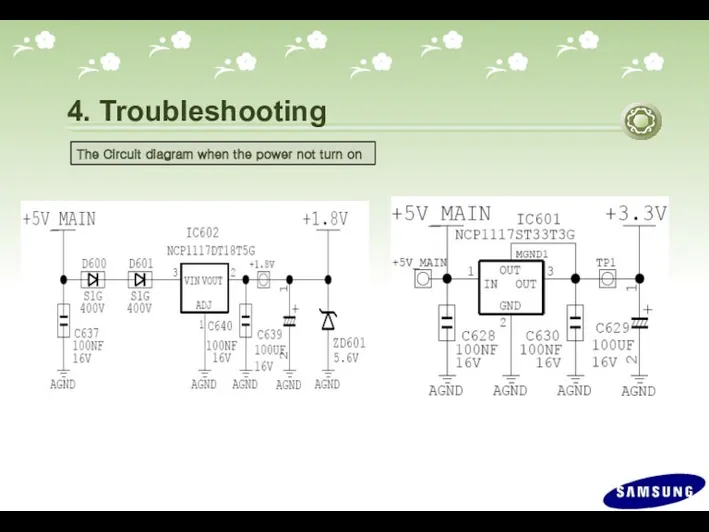
- 40. 4. Troubleshooting The Circuit diagram when the power not turn on
- 41. 4. Troubleshooting The Circuit diagram when the power not turn on
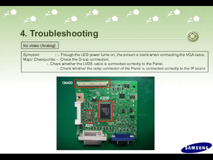
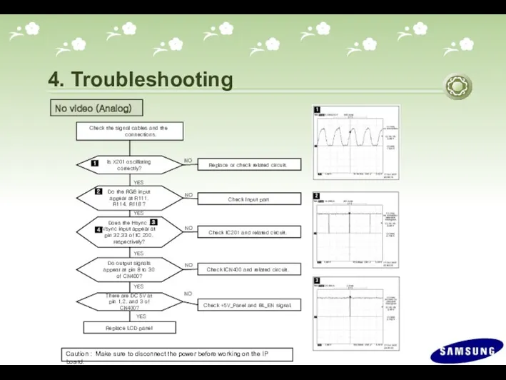
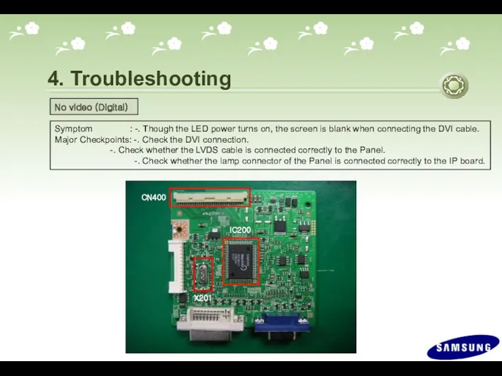
- 42. 4. Troubleshooting Symptom : -. Though the LED power turns on, the screen is blank when
- 43. 4. Troubleshooting Check IC201 and related circuit. Check +5V_Panel and BL_EN signal. Check the signal cables
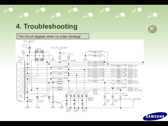
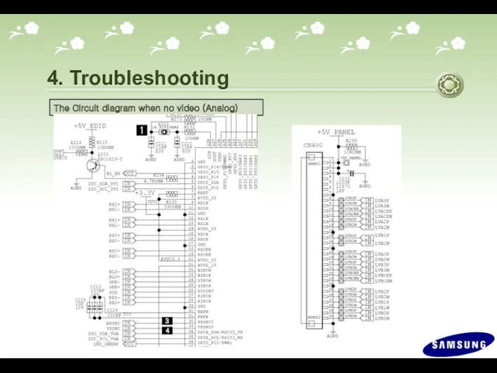
- 44. 4. Troubleshooting The Circuit diagram when no video (Analog) 2
- 45. 4. Troubleshooting The Circuit diagram when no video (Analog)
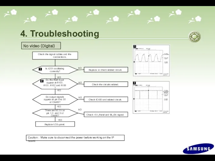
- 46. 4. Troubleshooting Symptom : -. Though the LED power turns on, the screen is blank when
- 47. 4. Troubleshooting Check +5V_Panel and BL_EN signal. Check the signal cables and the connections. Is X201
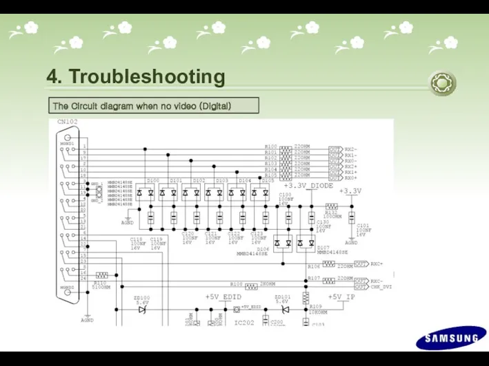
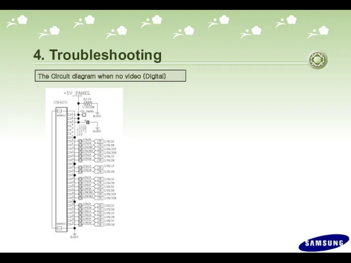
- 48. 4. Troubleshooting The Circuit diagram when no video (Digital) 2
- 49. 4. Troubleshooting The Circuit diagram when no video (Digital)
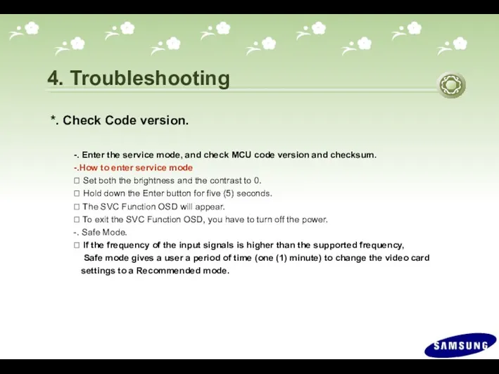
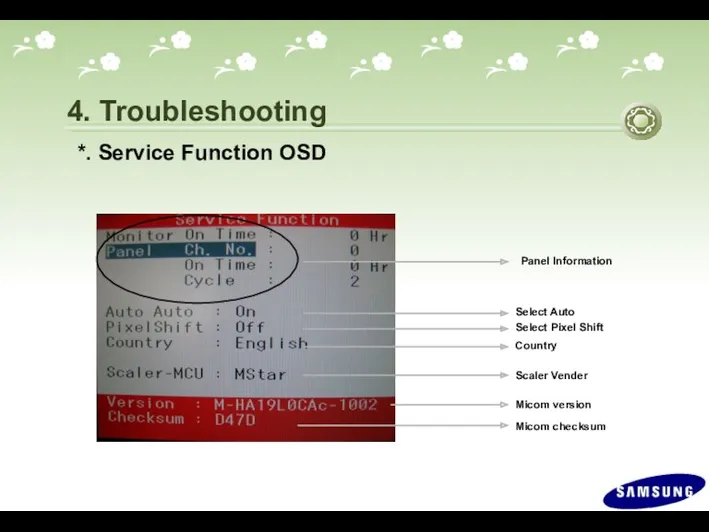
- 50. 4. Troubleshooting *. Check Code version. -. Enter the service mode, and check MCU code version
- 51. 4. Troubleshooting Select Auto Select Pixel Shift Panel Information Micom version Micom checksum Country Scaler Vender
- 52. *. To move next step. Press (+) key. 4. Troubleshooting
- 53. *. To select off/on. Press (-) key. 4. Troubleshooting
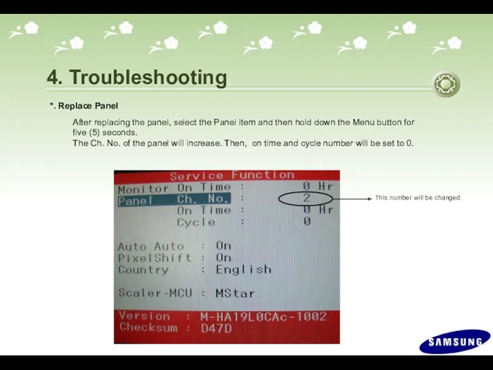
- 54. 4. Troubleshooting *. Replace Panel After replacing the panel, select the Panel item and then hold
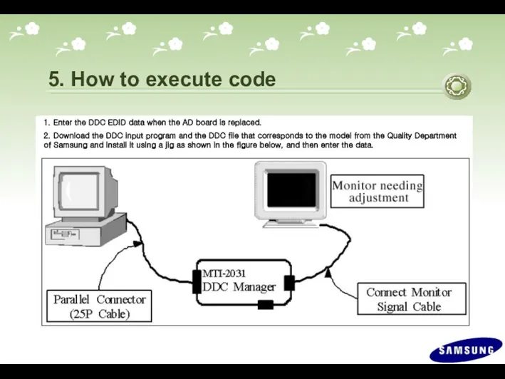
- 55. 5. How to execute code
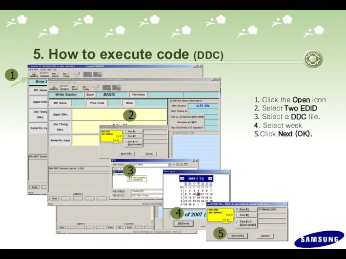
- 56. 5. How to execute code (DDC) 1. Click the Open icon 2. Select Two EDID 3.
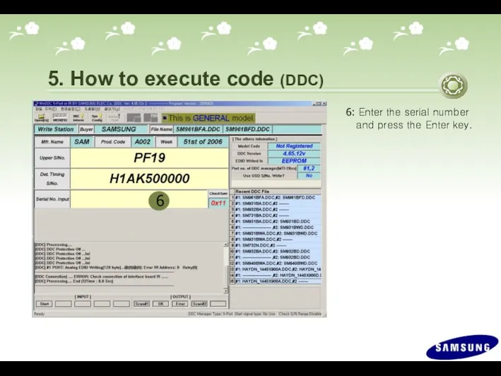
- 57. 6 6: Enter the serial number and press the Enter key. 5. How to execute code
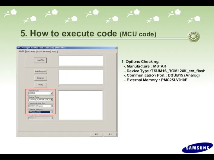
- 58. 1. Options Checking. -. Manufacture : MSTAR -. Device Type :TSUM16_ROM128K_ext_flash -. Communication Port : DSUB15
- 59. 2. After click the 'LoadFile' button , choose MCU code. 5. How to execute code (MCU
- 60. 3. ‘Auto Program' button choice. 5. How to execute code (MCU code)
- 61. 4. After the Program and Verify completed, execute hard power off/on. 5. How to execute code
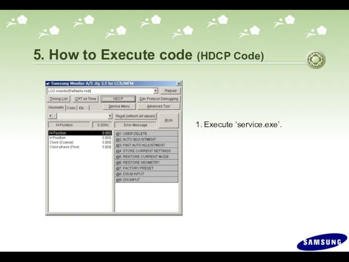
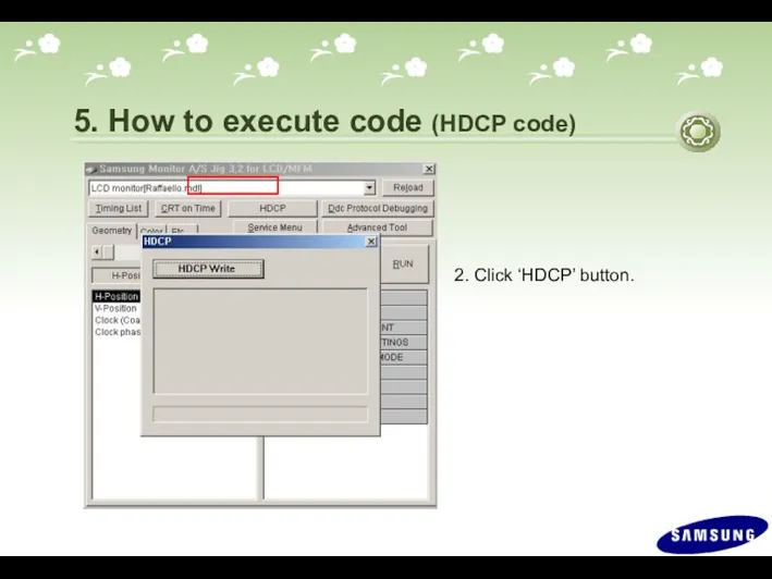
- 62. 5. How to Execute code (HDCP Code) 1. Execute ‘service.exe’.
- 63. 2. Click ‘HDCP’ button. 5. How to execute code (HDCP code)
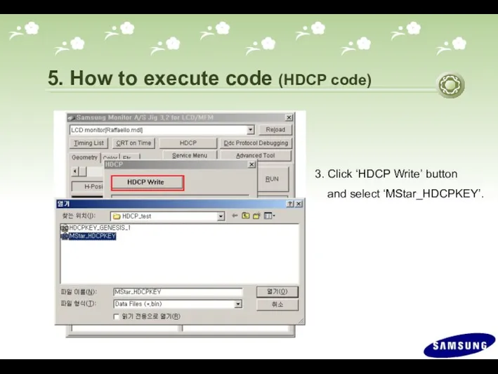
- 64. 3. Click ‘HDCP Write’ button and select ‘MStar_HDCPKEY’. 5. How to execute code (HDCP code)
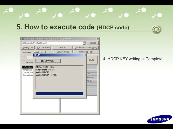
- 65. 4. HDCP KEY writing is Complete. 5. How to execute code (HDCP code)
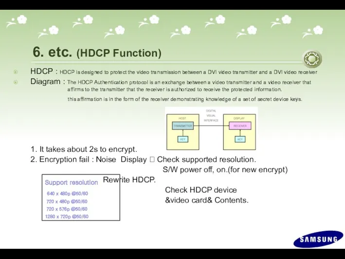
- 66. Support resolution 640 x 480p @50/60 720 x 480p @50/60 720 x 576p @50/60 1280 x
- 68. Скачать презентацию
Contents
Product Overview
Circuit Description
Assembly and Disassembly
Troubleshooting
How to Execute Code
Etc.
Contents
Product Overview
Circuit Description
Assembly and Disassembly
Troubleshooting
How to Execute Code
Etc.
1. Product Overview (Product Features)
*. Feature
-. Panel : 300cd/m2, 5ms,
1. Product Overview (Product Features)
*. Feature
-. Panel : 300cd/m2, 5ms,
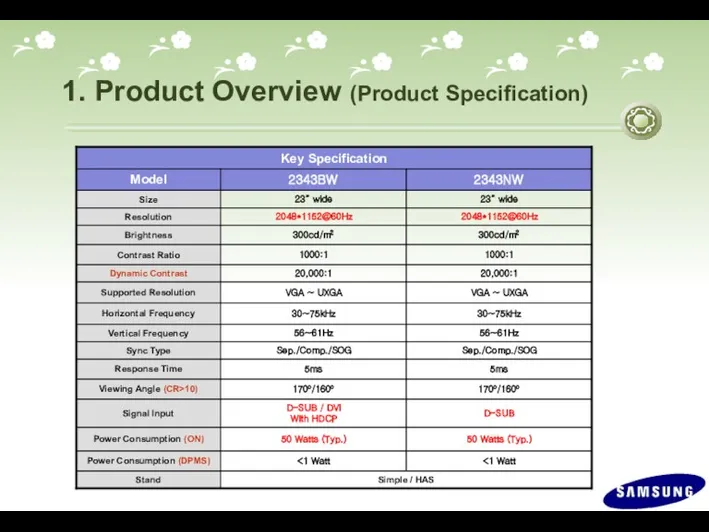
1. Product Overview (Product Specification)
1. Product Overview (Product Specification)
1. Product Overview (Product Specification)
1. Product Overview (Product Specification)
1. Product Overview (Product Specification)
1. Product Overview (Product Specification)
Magic color
Demo Mode
On
Off
Magic color
Full Mode
1. Product Overview
Magic color
Demo Mode
On
Off
Magic color
Full Mode
1. Product Overview

Magic color
Intelligent Mode
1. Product Overview (Magic Color)
Except Skin Tone
Magic color
Intelligent Mode
1. Product Overview (Magic Color)
Except Skin Tone
1. Product Overview (Connecting External Devices)
1. Product Overview (Connecting External Devices)
1. Product Overview (Supported Display Modes)
1. Product Overview (Supported Display Modes)
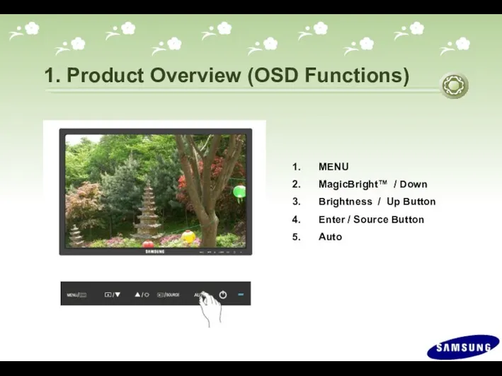
1. Product Overview (OSD Functions)
MENU
MagicBright™ / Down
Brightness / Up Button
Enter /
1. Product Overview (OSD Functions)
MENU
MagicBright™ / Down
Brightness / Up Button
Enter /
1. Product Overview (OSD Functions)
MENU Button : Open the OSD menu. Use
1. Product Overview (OSD Functions)
MENU Button : Open the OSD menu. Use
1. Product Overview (OSD Functions)
(4) Enter/ Source Button : Press this
1. Product Overview (OSD Functions)
(4) Enter/ Source Button : Press this
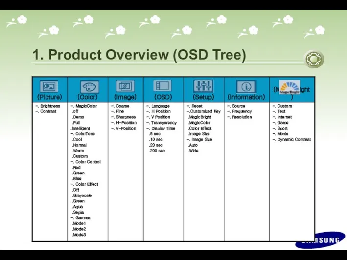
1. Product Overview (OSD Tree)
1. Product Overview (OSD Tree)
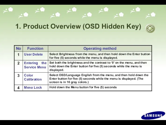
1. Product Overview (OSD Hidden Key)
1. Product Overview (OSD Hidden Key)
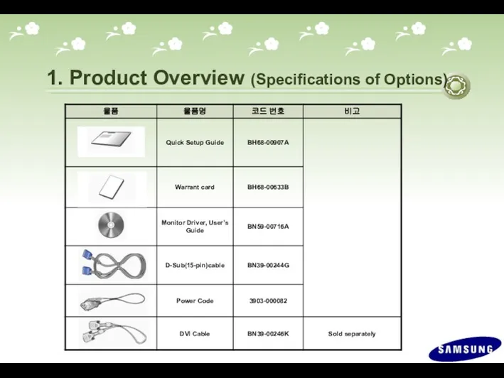
1. Product Overview (Specifications of Options)
1. Product Overview (Specifications of Options)
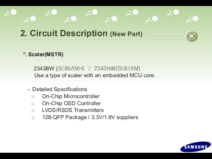
2. Circuit Description (New Part)
*. Scaler(MSTR)
2343BW (SE85AMH) / 2343NW(SE81AM)
2. Circuit Description (New Part)
*. Scaler(MSTR)
2343BW (SE85AMH) / 2343NW(SE81AM)
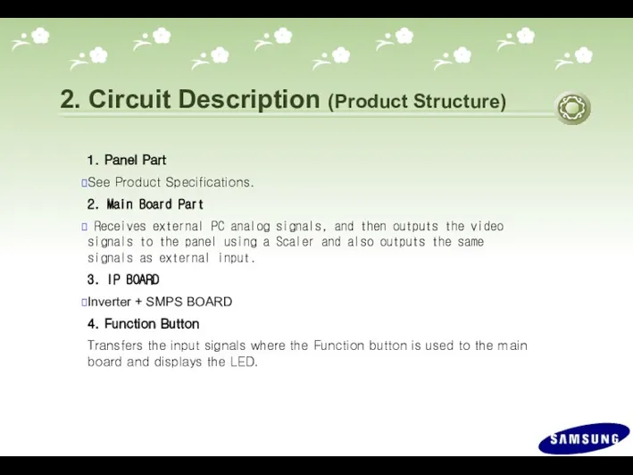
2. Circuit Description (Product Structure)
1. Panel Part
See Product Specifications.
2. Main Board
2. Circuit Description (Product Structure)
1. Panel Part
See Product Specifications.
2. Main Board
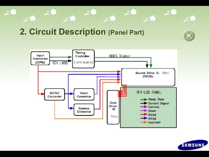
2. Circuit Description (Panel Part)
2. Circuit Description (Panel Part)
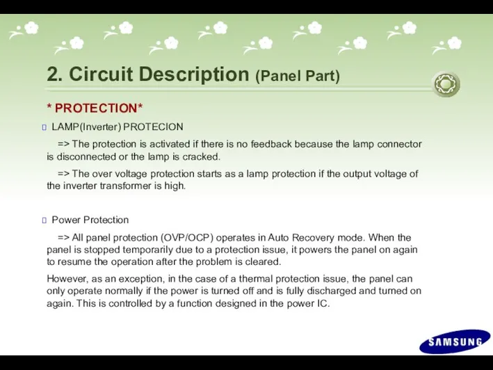
2. Circuit Description (Panel Part)
* PROTECTION*
LAMP(Inverter) PROTECION
=> The protection
2. Circuit Description (Panel Part)
* PROTECTION*
LAMP(Inverter) PROTECION
=> The protection
2. Circuit Description (Scaler Part)
P a n e l
5V
Mstar SE85AMH /
2. Circuit Description (Scaler Part)
P a n e l
5V
Mstar SE85AMH /
2. Circuit Description (Scaler Part)
P
A
N
E
L
24C08
EEPROM
1MB
Flash
Dual
Interface
Engine
Inverter
3.3V
Regulator
1.8V
Regulator
14.318MHz
XTAL
(PC)DIGITAL
Rx2+
Rx2-
Rx1+
Rx1-
Rx0+
Rx0-
RxC+
RxC-
(PC)ANALOG
R
G
B
HSYNC
VSYNC
Function Key
Display
Processing
Engine
LVDS
Panel
Interface
OSD
Clock
Generator
MCU
SE85AMH / SE81AM
+5
+5
8Bit
Stores the
MCU code (Hex)
Stores
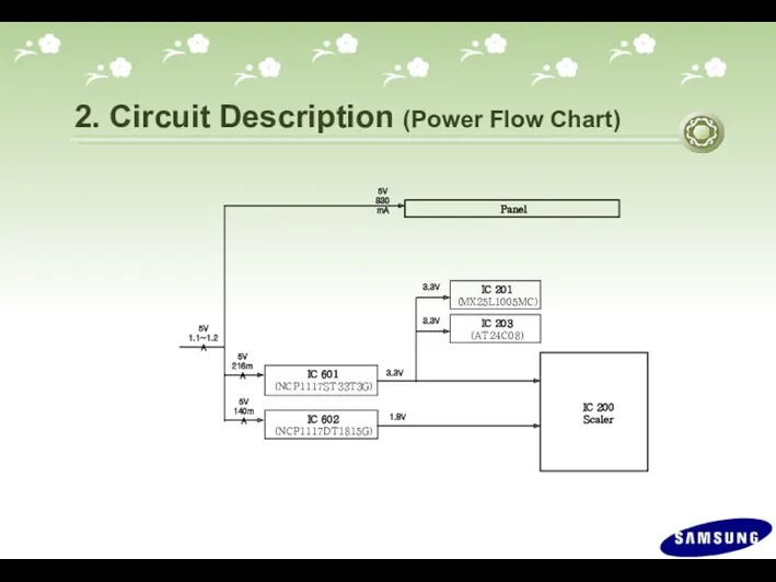
2. Circuit Description (Power Flow Chart)
IC 601
(NCP1117ST33T3G)
IC 602
(NCP1117DT1815G)
IC 203
(AT24C08)
IC 200
Scaler
5V
1.1~1.2A
3.3V
1.8V
IC 201
(MX25L1005MC)
Panel
5V
830
2. Circuit Description (Power Flow Chart)
IC 601
(NCP1117ST33T3G)
IC 602
(NCP1117DT1815G)
IC 203
(AT24C08)
IC 200
Scaler
5V
1.1~1.2A
3.3V
1.8V
IC 201
(MX25L1005MC)
Panel
5V
830
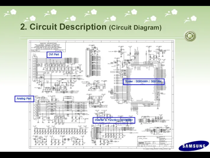
2. Circuit Description (Circuit Diagram)
2. Circuit Description (Circuit Diagram)
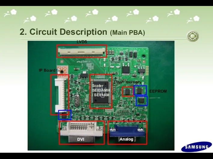
2. Circuit Description (Main PBA)
2. Circuit Description (Main PBA)
2. Circuit Description (Main PBA)
2. Circuit Description (Main PBA)
2. Circuit Description (IP Board - Dimming)
*. There are three methods.
2. Circuit Description (IP Board - Dimming)
*. There are three methods.
2. Circuit Description (IP Board)
SMPS Part
Consists of a line filter, an
2. Circuit Description (IP Board)
SMPS Part
Consists of a line filter, an
2. Circuit Description (IP Board Circuit Diagram)
Inverter Part
DC-Output
(Adapter_14V)
Dimming
Control
Block
Back Light
Lamp
Brightness
Changeable
(Micom)
Inverter
Transformer_1
Switching
FET_1,2
Inverter
Controller
(OZ960SN)
Back Light
Lamp
Connector_1
Back Light
Lamp
Connector_2
Back
2. Circuit Description (IP Board Circuit Diagram)
Inverter Part
DC-Output
(Adapter_14V)
Dimming
Control
Block
Back Light
Lamp
Brightness
Changeable
(Micom)
Inverter
Transformer_1
Switching
FET_1,2
Inverter
Controller
(OZ960SN)
Back Light
Lamp
Connector_1
Back Light
Lamp
Connector_2
Back
3. Assembly and Disassembly (SIMPLE STAND)
Caution : 1. Turn the monitor off
3. Assembly and Disassembly (SIMPLE STAND)
Caution : 1. Turn the monitor off
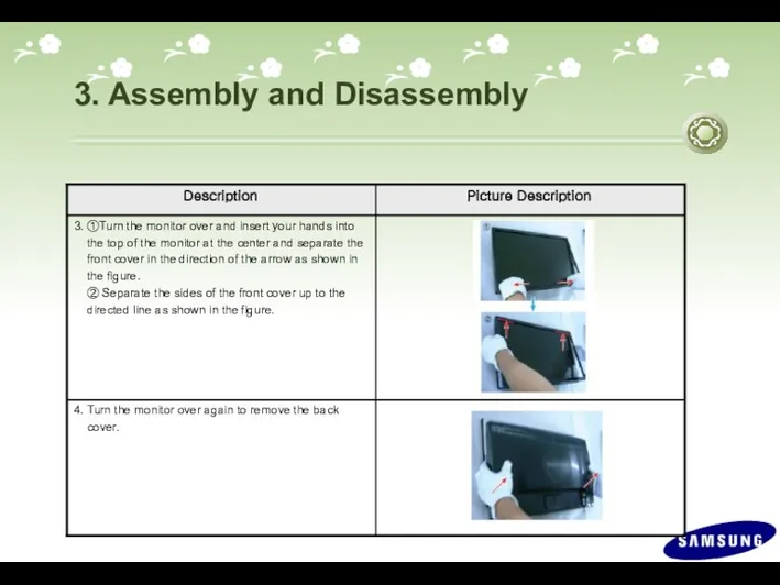
3. Assembly and Disassembly
3. Assembly and Disassembly
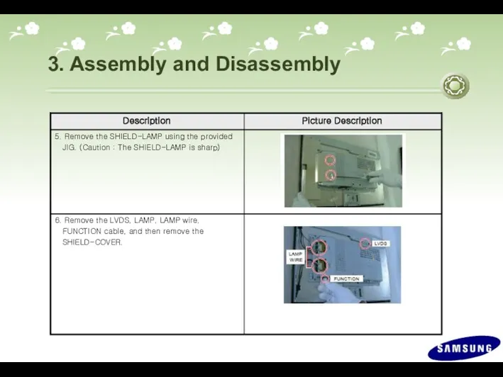
3. Assembly and Disassembly
3. Assembly and Disassembly
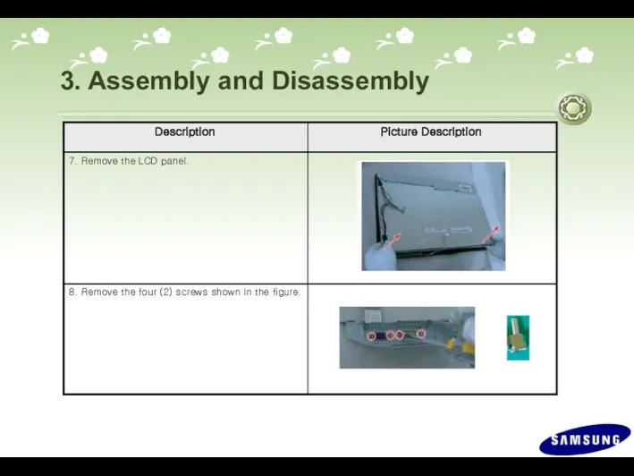
3. Assembly and Disassembly
3. Assembly and Disassembly
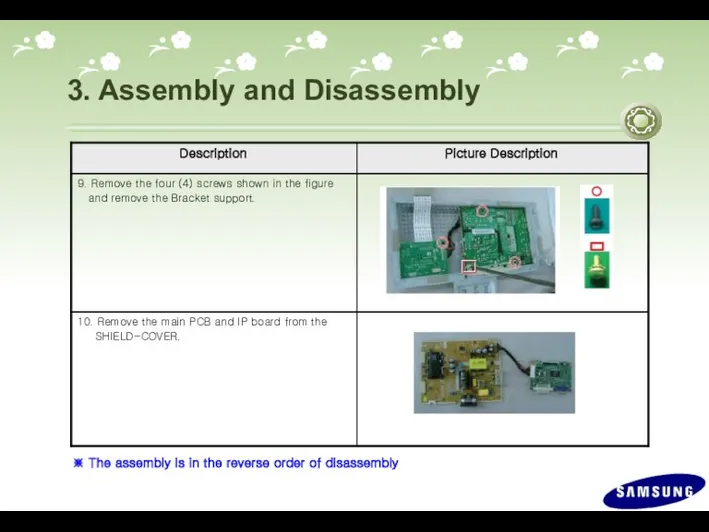
3. Assembly and Disassembly
※ The assembly is in the reverse order
3. Assembly and Disassembly
※ The assembly is in the reverse order
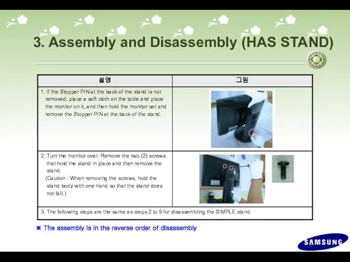
3. Assembly and Disassembly (HAS STAND)
※ The assembly is in the
3. Assembly and Disassembly (HAS STAND)
※ The assembly is in the
4. Troubleshooting
Checking Before repairing
1. Check the power state and the
4. Troubleshooting
Checking Before repairing
1. Check the power state and the
4. Troubleshooting
*. Other simple diagnostics
No power (No video and Function LED
4. Troubleshooting
*. Other simple diagnostics
No power (No video and Function LED
4. Troubleshooting
Symptom : -. When turning on the Power button after
4. Troubleshooting
Symptom : -. When turning on the Power button after
4. Troubleshooting
No power
Check IC 601 and related circuit.
Check IC 602 and
4. Troubleshooting
No power
Check IC 601 and related circuit.
Check IC 602 and
4. Troubleshooting
The Circuit diagram when the power not turn on
4. Troubleshooting
The Circuit diagram when the power not turn on
4. Troubleshooting
The Circuit diagram when the power not turn on
4. Troubleshooting
The Circuit diagram when the power not turn on
4. Troubleshooting
Symptom : -. Though the LED power turns on, the
4. Troubleshooting
Symptom : -. Though the LED power turns on, the
4. Troubleshooting
Check IC201 and related circuit.
Check +5V_Panel and BL_EN signal.
Check the
4. Troubleshooting
Check IC201 and related circuit.
Check +5V_Panel and BL_EN signal.
Check the
4. Troubleshooting
The Circuit diagram when no video (Analog)
2
4. Troubleshooting
The Circuit diagram when no video (Analog)
2
4. Troubleshooting
The Circuit diagram when no video (Analog)
4. Troubleshooting
The Circuit diagram when no video (Analog)
4. Troubleshooting
Symptom : -. Though the LED power turns on, the
4. Troubleshooting
Symptom : -. Though the LED power turns on, the
4. Troubleshooting
Check +5V_Panel and BL_EN signal.
Check the signal cables and the
4. Troubleshooting
Check +5V_Panel and BL_EN signal.
Check the signal cables and the
4. Troubleshooting
The Circuit diagram when no video (Digital)
2
4. Troubleshooting
The Circuit diagram when no video (Digital)
2
4. Troubleshooting
The Circuit diagram when no video (Digital)
4. Troubleshooting
The Circuit diagram when no video (Digital)
4. Troubleshooting
*. Check Code version.
-. Enter the service mode, and check
4. Troubleshooting
*. Check Code version.
-. Enter the service mode, and check
4. Troubleshooting
Select Auto
Select Pixel Shift
Panel Information
Micom version
Micom checksum
Country
Scaler Vender
*. Service Function
4. Troubleshooting
Select Auto
Select Pixel Shift
Panel Information
Micom version
Micom checksum
Country
Scaler Vender
*. Service Function
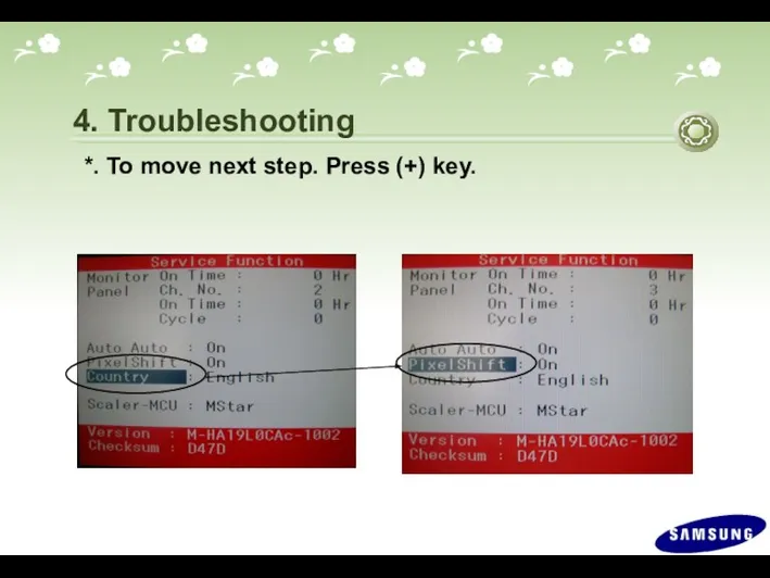
*. To move next step. Press (+) key.
4. Troubleshooting
*. To move next step. Press (+) key.
4. Troubleshooting
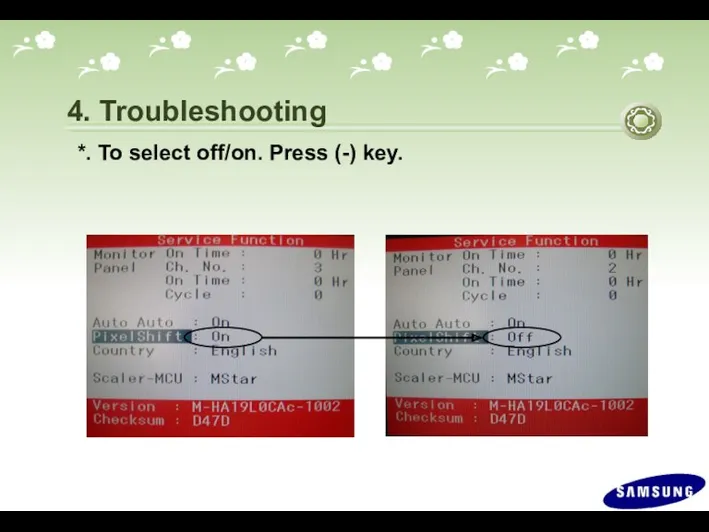
*. To select off/on. Press (-) key.
4. Troubleshooting
*. To select off/on. Press (-) key.
4. Troubleshooting
4. Troubleshooting
*. Replace Panel
After replacing the panel, select the Panel
4. Troubleshooting
*. Replace Panel
After replacing the panel, select the Panel
5. How to execute code
5. How to execute code
5. How to execute code (DDC)
1. Click the Open icon
2. Select
5. How to execute code (DDC)
1. Click the Open icon
2. Select
6
6: Enter the serial number
and press the Enter key.
5.
6
6: Enter the serial number
and press the Enter key.
5.
1. Options Checking.
-. Manufacture : MSTAR
-. Device Type :TSUM16_ROM128K_ext_flash
1. Options Checking.
-. Manufacture : MSTAR
-. Device Type :TSUM16_ROM128K_ext_flash
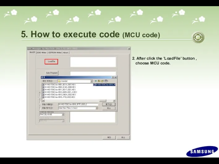
2. After click the 'LoadFile' button ,
choose MCU code.
5.
2. After click the 'LoadFile' button ,
choose MCU code.
5.
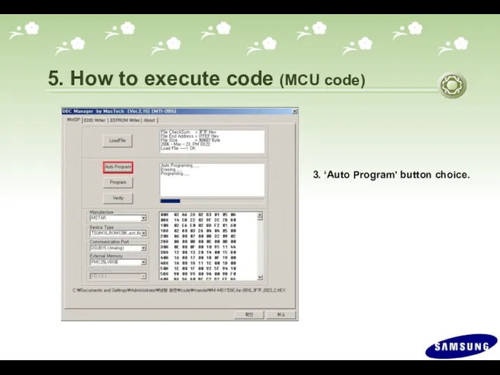
3. ‘Auto Program' button choice.
5. How to execute code (MCU
3. ‘Auto Program' button choice.
5. How to execute code (MCU
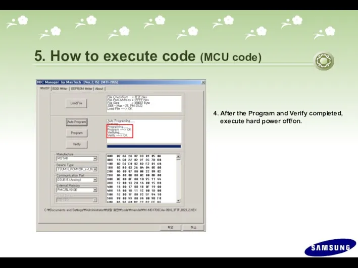
4. After the Program and Verify completed,
execute hard power
4. After the Program and Verify completed,
execute hard power
5. How to Execute code (HDCP Code)
1. Execute ‘service.exe’.
5. How to Execute code (HDCP Code)
1. Execute ‘service.exe’.
2. Click ‘HDCP’ button.
5. How to execute code (HDCP code)
2. Click ‘HDCP’ button.
5. How to execute code (HDCP code)
3. Click ‘HDCP Write’ button
and select ‘MStar_HDCPKEY’.
5. How to execute
3. Click ‘HDCP Write’ button
and select ‘MStar_HDCPKEY’.
5. How to execute
4. HDCP KEY writing is Complete.
5. How to execute code (HDCP
4. HDCP KEY writing is Complete.
5. How to execute code (HDCP
Support resolution
640 x 480p @50/60
720 x 480p @50/60
720
Support resolution
640 x 480p @50/60
720 x 480p @50/60
720
 Новогодняя сказка 2014!
 Параллелограмм, прямоугольник, ромб, квадрат
 Невербальные средства коммуникации
 Логика. Системы логических уравнений
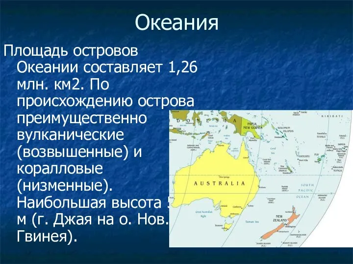 7 класс: Океания. Страны
 Молитва сердце очищает. Должники
 Скалярное произведение векторов. Геометрия 9 класс
 Урок-игра по роману А.С.Пушкина Дубровский
 Lactacyd Mailer +VO
 Алгоритм и его формальное исполнение
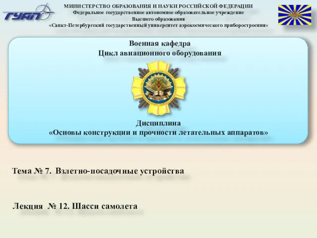 Шасси самолета
 Брендинг территории: Архангельская область
 Решение тестовых задач на движение (подготовка к ЕГЭ)
 Лабораторная работа №3
 Повітря забруднення
 Классный час на тему: Права и обязанности школьника
 Гетьманські столиці України
 Формирование толерантности на уроках и во внеклассной работе как средство успешной социализации младших школьников.
 Информационно-коммуникационная технология (Шесть шляп мышления)
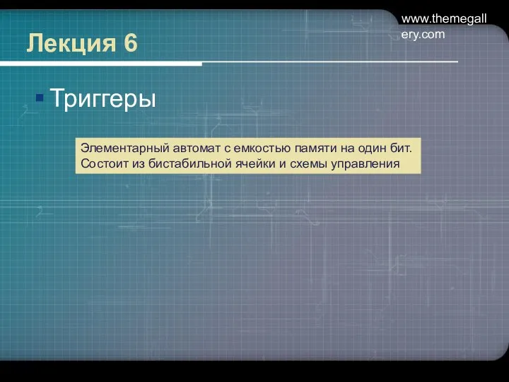 Триггеры. (Лекция 6)
 Родительское собрание Проблемы воспитания
 Реализация стратегии развития ОАО РЖД в современных условиях
 Сетевое взаимодействие как средство развития профессиональной компетентности воспитателей ДОУ
 Политическая полиция в первой половине XIX века
 Основные классы методов получения наночастиц
 Обучение работе с обращениями в GSD (подрядчики)
 Реконструкция канализационной насосной станции
 Действия с десятичными дробями