- Half-Wavelength Dipole Antenna

Содержание

Simulation Geometry and Setup
Antenna diameter is d = l/100
Antenna length is
Simulation Geometry and Setup
Antenna diameter is d = l/100
Antenna length is
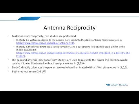
Antenna Reciprocity
To demonstrate reciprocity, two studies are performed.
In Study 1, a
Antenna Reciprocity
To demonstrate reciprocity, two studies are performed.
In Study 1, a
 Родина моя - Россия
 Зір тварин
 Агентство маркетинговых исследований
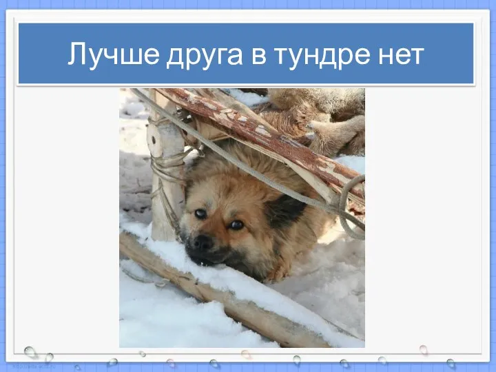 Лучше друга в тундре нет (к уроку Культура народов Ямала)
 ООО Аптека Исцеление
 Педагогическое общение
 Всенощное бдение. Великая вечерня (окончание)
 Future Tenses
 ВКР: Электрификация и автоматизация технологических процессов при строительстве станции Улица Новаторов
 Роман А.С.Пушкина Евгений Онегин
 Сбор и хранение медицинских отходов
 Респираторно - синцитиальная инфекция
 Дамудың қатерлі кезеңдері
 Эффективность и справедливость в бюджетных расходах. Фискальный федерализм
 Возрастные особенности онтогенеза
 Бюджетный федерализм
 Театральный словарь
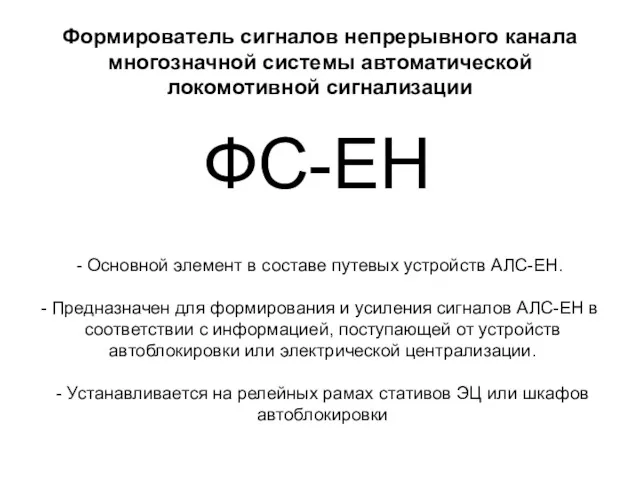 Формирователь сигналов непрерывного канала многозначной системы автоматической локомотивной сигнализации
 Группа в социальном пространстве. Признаки и функции коллектива, методика его формирования
 Промежуточный мозг
 Химические реакции
 تابع الفصل الثالث برنامج العروض التقديمية
 Адаптивная физическая культура и ее значение в коррекции нарушений у детей с ограниченными возможностями здоровья
 Презентация MsPP Дни воинской славы России, часть 1
 Ф.А.Искандер - советский и российский прозаик и абхазский поэт
 Мультимедийная презентация по реализации задач образовательной области Здоровье
 Жизнелюбие и отношения полов
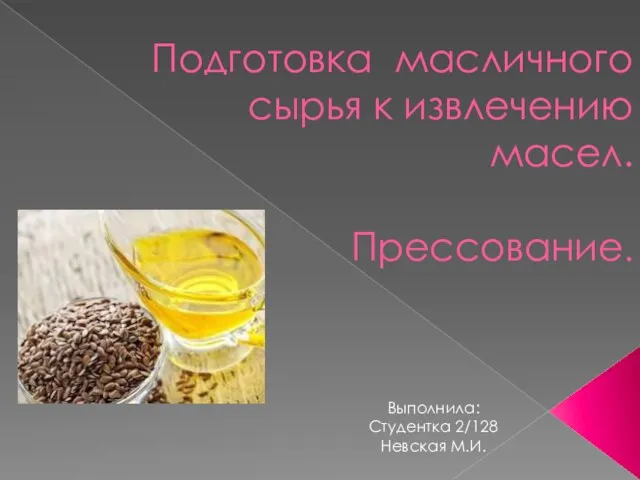 Подготовка масличного сырья к извлечению. Прессование