- Manual de Treinamento

Содержание
- 2. Ⅰ. Concept Ⅱ. Specification Ⅲ. Product Image Ⅳ. Inner Feature Ⅴ. Disassemble Ⅵ. Troubleshooting Ⅶ. Feature
- 3. Ⅰ. Product Concept “The Most Affordable LED TV ever” Picture Quality : Direct LED backlighting Panel
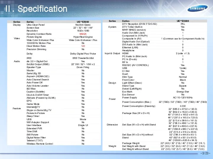
- 4. Ⅱ. Specification -3/23-
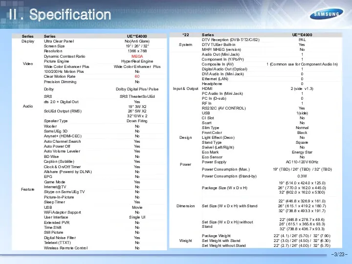
- 5. Ⅱ. Specification -3/23-
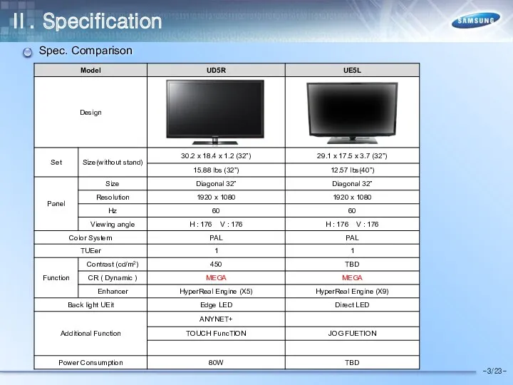
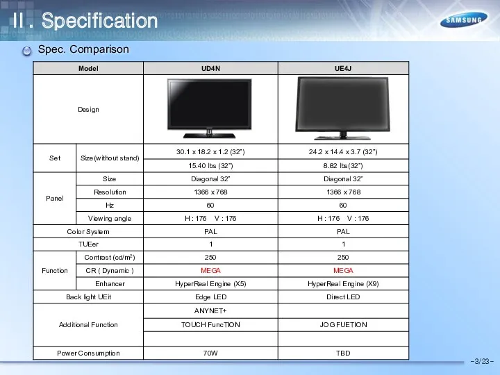
- 6. Ⅱ. Specification -3/23- Spec. Comparison
- 7. Ⅱ. Specification -3/23- Spec. Comparison
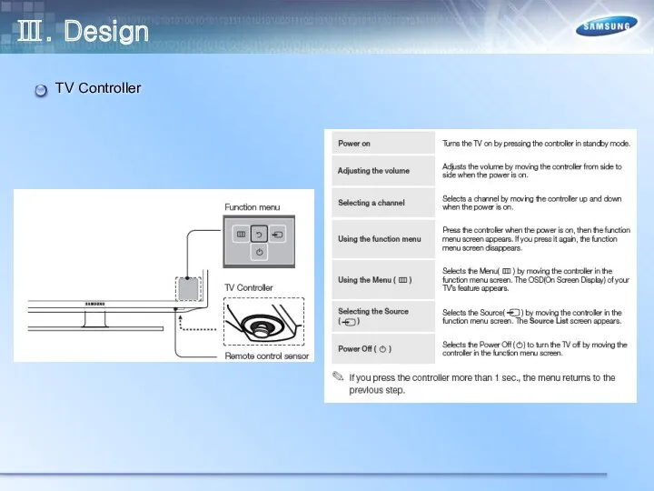
- 8. Ⅲ. Design TV Controller
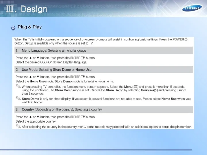
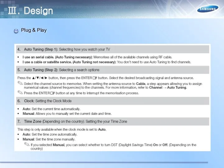
- 9. Ⅲ. Design Plug & Play
- 10. Ⅲ. Design Plug & Play
- 11. Ⅲ. Design Plug & Play
- 12. Ⅲ. Design Connectios
- 13. Ⅲ. Design Connectios
- 14. Ⅲ. Design Changing the Input Source
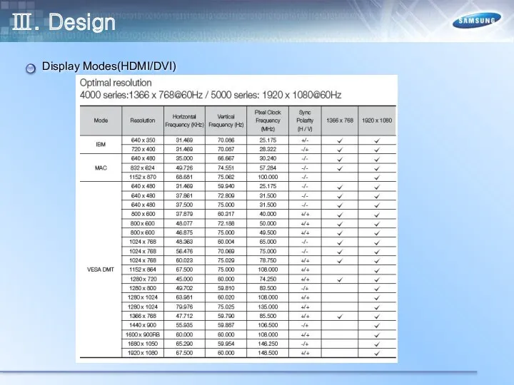
- 15. Ⅲ. Design Display Modes(HDMI/DVI)
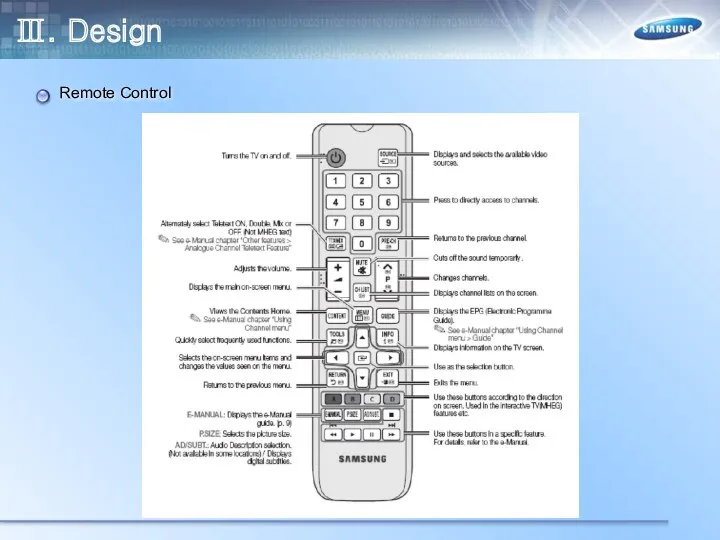
- 16. Ⅲ. Design Remote Control
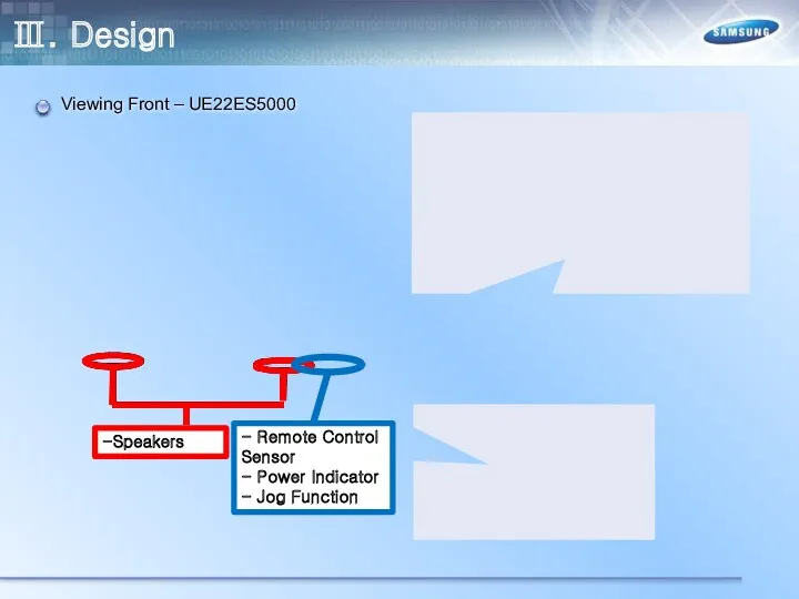
- 17. Ⅲ. Design Viewing Front – UE22ES5000 -Speakers - Remote Control Sensor - Power Indicator - Jog
- 18. Ⅲ. Design Rear – UE22ES5000
- 19. Ⅲ. Design Viewing Front - UE32EH5000 -Speakers - Remote Control Sensor - Power Indicator - Jog
- 20. Ⅲ. Design Rear - UE32EH5000
- 21. Ⅲ. Design Viewing Front - UE40EH5000 - Speakers - Remote Control Sensor - Power Indicator -
- 22. Ⅲ. Design Rear - UE40EH5000
- 23. Ⅲ. Design Viewing Front - UE46EH5000 -Speakers - Remote Control Sensor - Power Indicator - Jog
- 24. Ⅲ. Design Rear - UE46EH5000
- 25. Ⅲ. Design Viewing Front – UE19ES4000 -Speakers - Remote Control Sensor - Power Indicator - Jog
- 26. Ⅲ. Design Rear – UE19ES4000
- 27. Ⅲ. Design Viewing Front - UE26EH4000 -Speakers - Remote Control Sensor - Power Indicator - Jog
- 28. Ⅲ. Design Rear – UE26EH4000
- 29. Ⅲ. Design Viewing Front - UE32EH4000 - Speakers - Remote Control Sensor - Power Indicator -
- 30. Ⅲ. Design Rear - UE32EH4000
- 31. Ⅳ. Inner Feature LAY OUT – UE19ES5000 Main Board SMPS Board Speaker (R) Speaker (L)
- 32. Ⅳ. Inner Feature LAY OUT – UE32EH5000 Main Board SMPS Board Speaker (R) Speaker (L)
- 33. Ⅳ. Inner Feature LAY OUT – UE40EH5000 Main Board SMPS Board Speaker (R) Speaker (L)
- 34. Ⅳ. Inner Feature LAY OUT – UE46EH5000 Main Board SMPS Board Speaker (R) Speaker (L)
- 35. Ⅳ. Inner Feature LAY OUT – UE19ES4000 Main Board SMPS Board Speaker (R) Speaker (L)
- 36. Ⅳ. Inner Feature Main Board SMPS Board Speaker (R) Speaker (L) LAY OUT – UE26EH4000
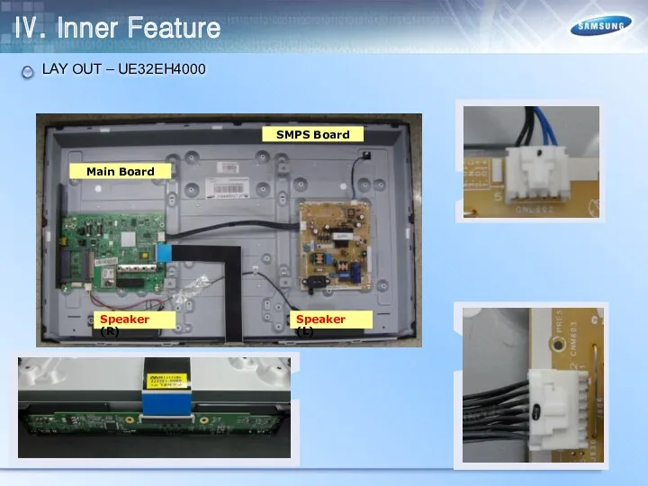
- 37. Main Board SMPS Board Speaker (R) Speaker (L) Ⅳ. Inner Feature LAY OUT – UE32EH4000
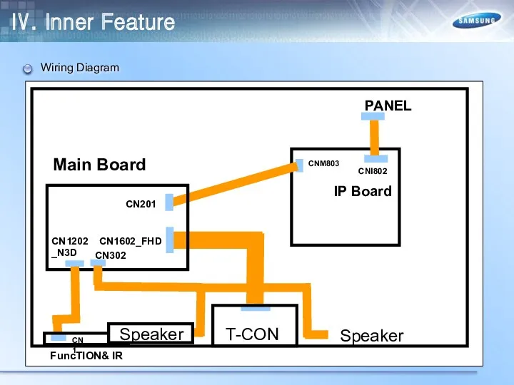
- 38. Ⅳ. Inner Feature Wiring Diagram
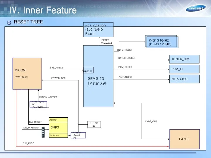
- 39. Ⅳ. Inner Feature RESET TREE SEMS 23 (Mstar X9) SMPS Standby B+ Power SW_POWER POWER_DET PANEL
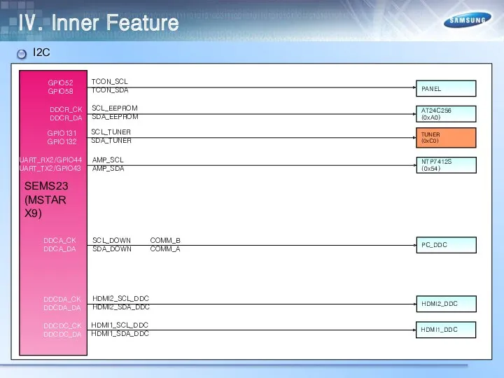
- 40. Ⅳ. Inner Feature I2C SEMS23 (MSTAR X9) UART_RX2/GPIO44 UART_TX2/GPIO43 DDCR_CK DDCR_DA AT24C256 (0xA0) SCL_EEPROM SDA_EEPROM TUNER
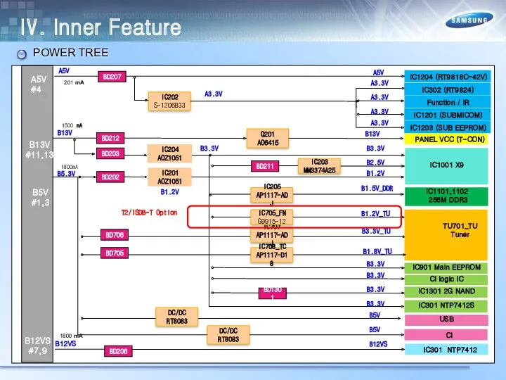
- 41. Ⅳ. Inner Feature POWER TREE
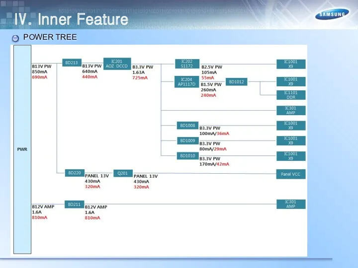
- 42. Ⅳ. Inner Feature POWER TREE
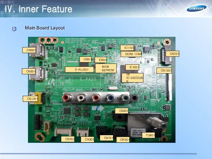
- 43. Ⅳ. Inner Feature Main Board Layout
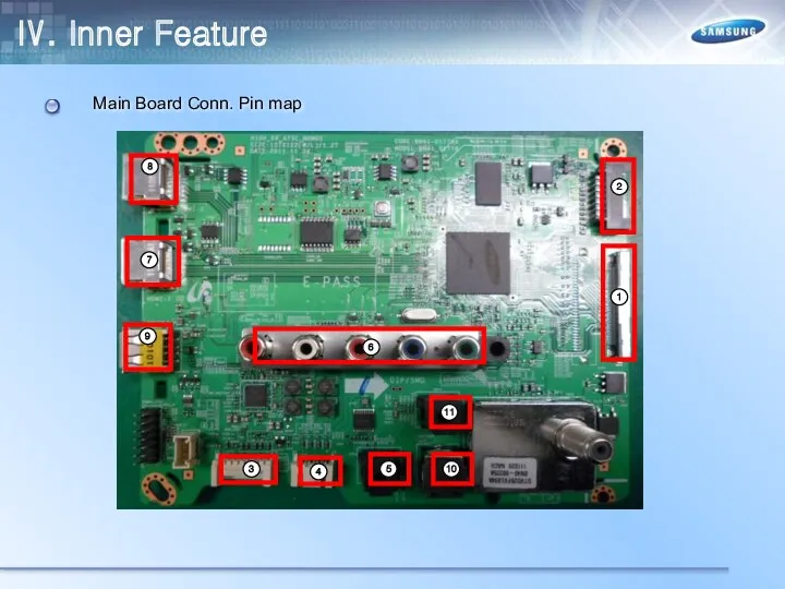
- 44. Ⅳ. Inner Feature Main Board Conn. Pin map
- 45. Ⅳ. Inner Feature Main Board Conn. Pin map
- 46. Ⅳ. Inner Feature Main Board Conn. Pin map
- 47. Ⅳ. Inner Feature Main Board Conn. Pin map
- 48. Ⅴ. Disassembly Place monitor face down on cushioned table. 2. Remove 4 screws from the stand.
- 49. Ⅴ. Disassembly 3. Remove stand. 4. 32/40" : Remove 1 screw of cover jack 46" :
- 50. Ⅴ. Disassembly 5. 32/40" : Remove the cover jack 46" : Remove the rear cover. 6.
- 51. Ⅴ. Disassembly 7. Remove the screws of rear-cover. 8. Remove the rear-cover. 40 32 46 46
- 52. Ⅴ. Disassembly 9.Remove the screws of main board and IP board and Panel. 10. Remove the
- 53. Ⅴ. Disassembly 11. Remove the LVDS cable and Panel drive cable 12. Completed disassembly
- 54. Ⅴ. Disassembly Place monitor face down on cushioned table. 2. Remove 4 screws from the stand.
- 55. Ⅴ. Disassembly 3. Remove stand. 4. Remove the 1 screw of cover jack
- 56. Ⅴ. Disassembly 5. Remove the cover jack. 6. Disconnect the function assy cable..
- 57. Ⅴ. Disassembly 7. Remove the screws of rear-cover. 8. Remove the rear-cover. 32 26
- 58. Ⅴ. Disassembly 9.Remove the screws of main board and IP board and Panel. 10. Remove the
- 59. Ⅴ. Disassembly 11. Remove the LVDS cable and Panel drive cable 12. Completed disassembly
- 60. Ⅴ. Disassembly(PTC) 1. Place monitor face up on cushioned table. 2. remove the T-CON Cover
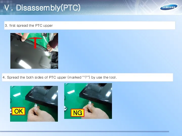
- 61. Ⅴ. Disassembly(PTC) 3. first spread the PTC upper 4. Spread the both sides of PTC upper
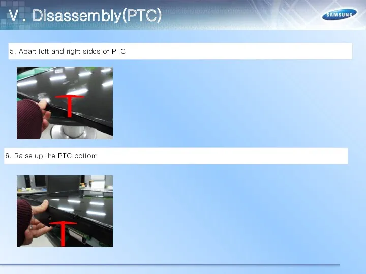
- 62. Ⅴ. Disassembly(PTC) 5. Apart left and right sides of PTC 6. Raise up the PTC bottom
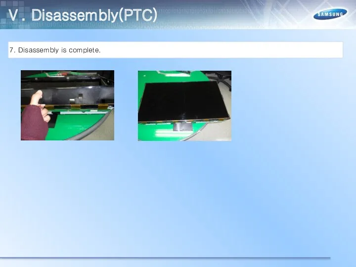
- 63. Ⅴ. Disassembly(PTC) 7. Disassembly is complete.
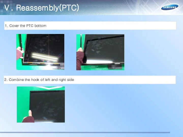
- 64. Ⅴ. Reassembly(PTC) 1. Cover the PTC bottom 2. Combine the hook of left and right side
- 65. Ⅴ. Disassembly(PTC) 3. Check to combine the top and bottom ※caution ※ Combine to stuck the
- 66. Ⅴ. Disassembly(PTC) 3. Check to combine the top and bottom
- 67. Ⅴ. Disassembly(PTC) ※caution ※ Combine to stuck the PTC Rib in middle molde
- 68. Ⅴ. Disassembly(PTC) 4. Disassembly is complete.
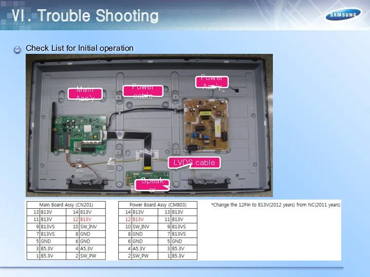
- 69. Ⅵ. Trouble Shooting Check List for Initial operation
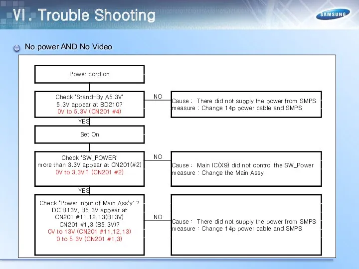
- 70. Ⅵ. Trouble Shooting No power AND No Video
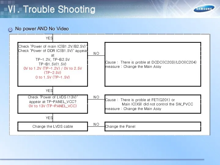
- 71. Ⅵ. Trouble Shooting No power AND No Video
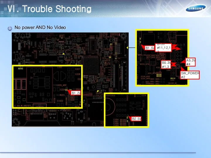
- 72. Ⅵ. Trouble Shooting No power AND No Video
- 73. Ⅵ. Trouble Shooting RS232C code
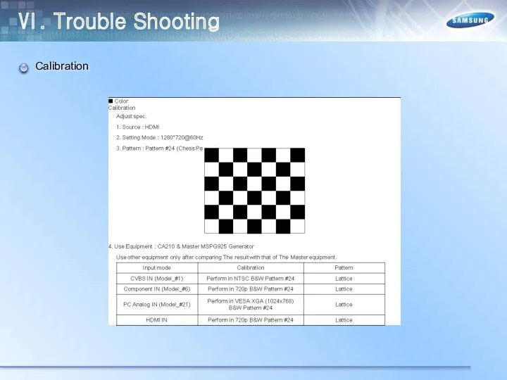
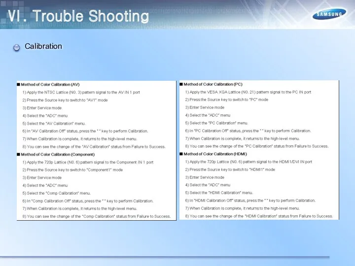
- 74. Ⅵ. Trouble Shooting Calibration
- 75. Ⅵ. Trouble Shooting Calibration
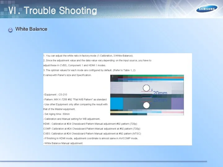
- 76. Ⅵ. Trouble Shooting White Balance
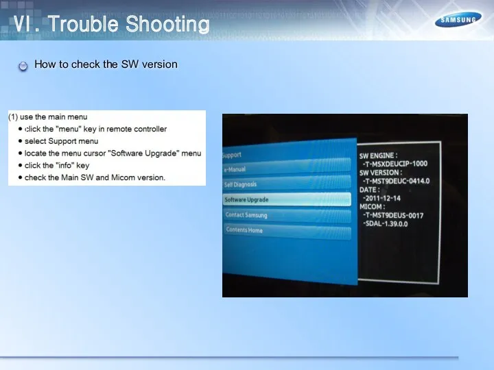
- 77. Ⅵ. Trouble Shooting How to check the SW version
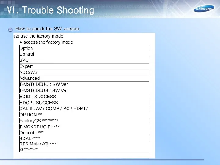
- 78. Ⅵ. Trouble Shooting How to check the SW version
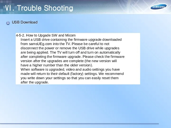
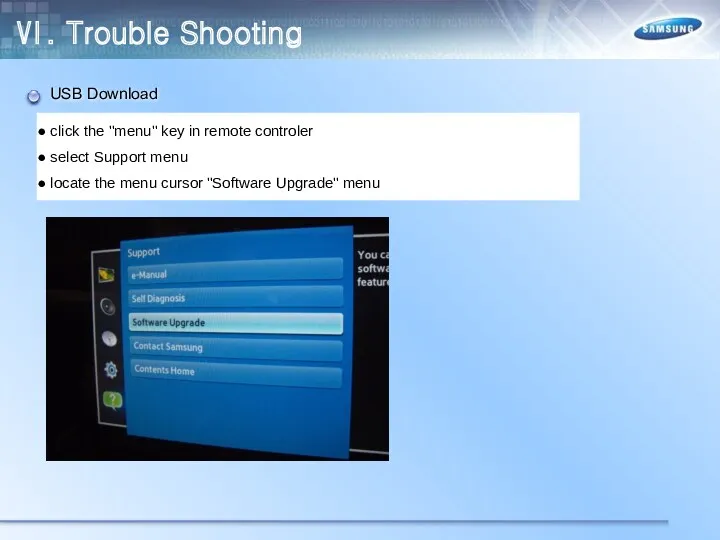
- 79. Ⅵ. Trouble Shooting USB Download
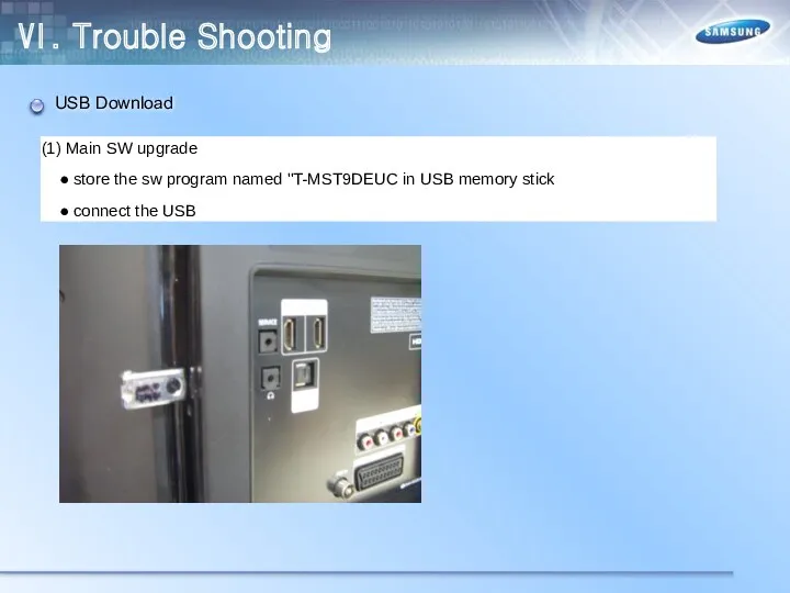
- 80. Ⅵ. Trouble Shooting USB Download
- 81. Ⅵ. Trouble Shooting USB Download
- 83. Скачать презентацию
Ⅰ. Concept
Ⅱ. Specification
Ⅲ. Product Image
Ⅳ. Inner Feature
Ⅴ. Disassemble
Ⅵ. Troubleshooting
Ⅶ. Feature
Ⅰ. Concept
Ⅱ. Specification
Ⅲ. Product Image
Ⅳ. Inner Feature
Ⅴ. Disassemble
Ⅵ. Troubleshooting
Ⅶ. Feature
Ⅰ. Product Concept
“The Most Affordable LED TV ever”
Picture Quality : Direct
Ⅰ. Product Concept
“The Most Affordable LED TV ever”
Picture Quality : Direct

Ⅱ. Specification
-3/23-
Ⅱ. Specification
-3/23-
Ⅱ. Specification
-3/23-
Ⅱ. Specification
-3/23-
Ⅱ. Specification
-3/23-
Spec. Comparison
Ⅱ. Specification
-3/23-
Spec. Comparison
Ⅱ. Specification
-3/23-
Spec. Comparison
Ⅱ. Specification
-3/23-
Spec. Comparison
Ⅲ. Design
TV Controller
Ⅲ. Design
TV Controller
Ⅲ. Design
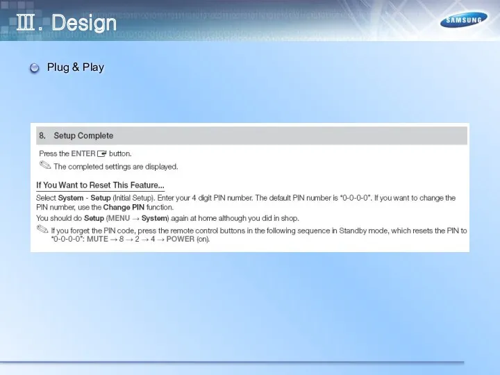
Plug & Play
Ⅲ. Design
Plug & Play
Ⅲ. Design
Plug & Play
Ⅲ. Design
Plug & Play
Ⅲ. Design
Plug & Play
Ⅲ. Design
Plug & Play
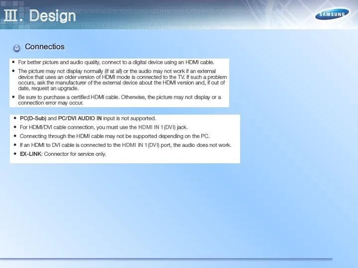
Ⅲ. Design
Connectios
Ⅲ. Design
Connectios
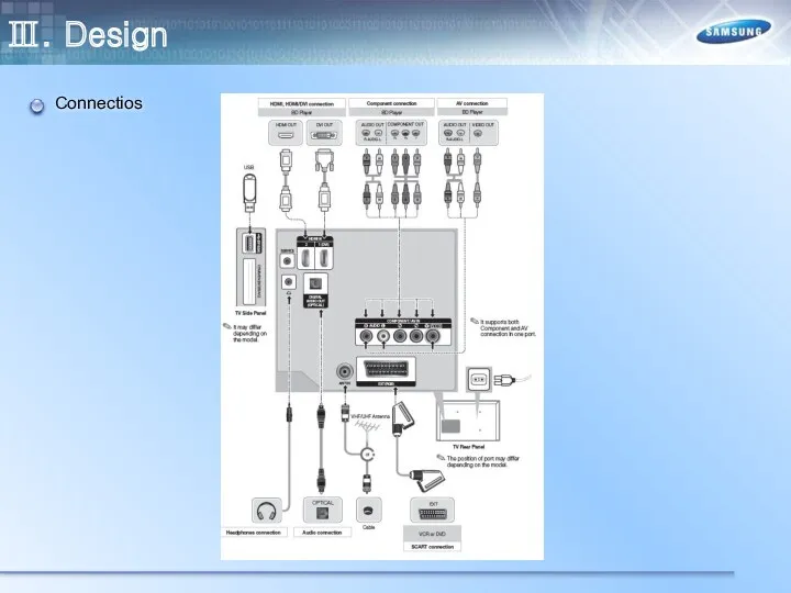
Ⅲ. Design
Connectios
Ⅲ. Design
Connectios
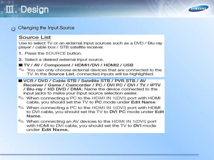
Ⅲ. Design
Changing the Input Source
Ⅲ. Design
Changing the Input Source
Ⅲ. Design
Display Modes(HDMI/DVI)
Ⅲ. Design
Display Modes(HDMI/DVI)
Ⅲ. Design
Remote Control
Ⅲ. Design
Remote Control
Ⅲ. Design
Viewing Front – UE22ES5000
-Speakers
- Remote Control Sensor
- Power Indicator
- Jog Function
Ⅲ. Design
Viewing Front – UE22ES5000
-Speakers
- Remote Control Sensor
- Power Indicator
- Jog Function
Ⅲ. Design
Rear – UE22ES5000
Ⅲ. Design
Rear – UE22ES5000
Ⅲ. Design
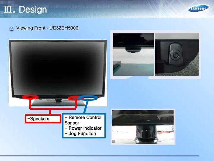
Viewing Front - UE32EH5000
-Speakers
- Remote Control Sensor
- Power Indicator
- Jog Function
Ⅲ. Design
Viewing Front - UE32EH5000
-Speakers
- Remote Control Sensor
- Power Indicator
- Jog Function
Ⅲ. Design
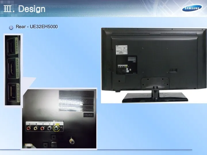
Rear - UE32EH5000
Ⅲ. Design
Rear - UE32EH5000
Ⅲ. Design
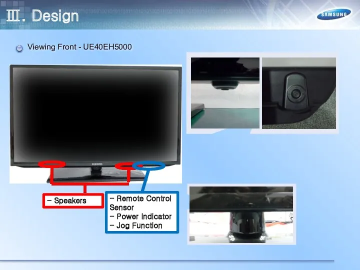
Viewing Front - UE40EH5000
- Speakers
- Remote Control Sensor
- Power Indicator
- Jog
Ⅲ. Design
Viewing Front - UE40EH5000
- Speakers
- Remote Control Sensor
- Power Indicator
- Jog
Ⅲ. Design
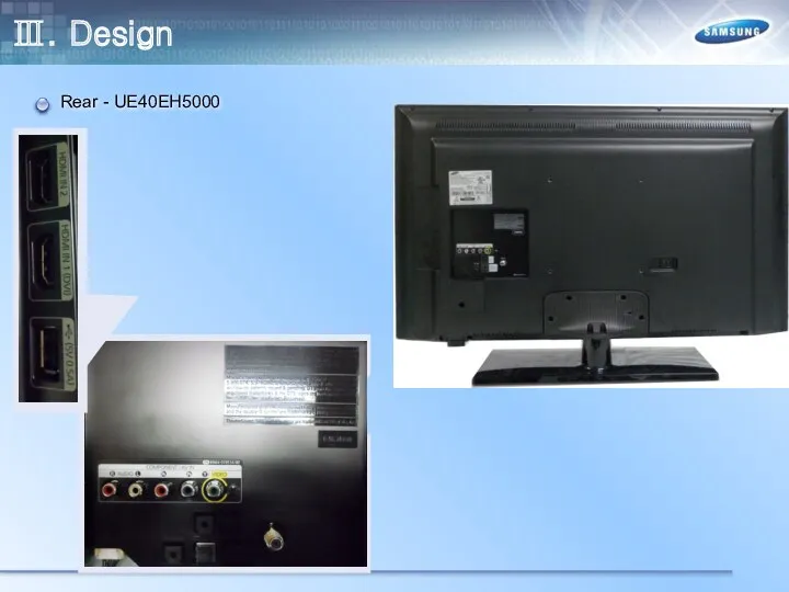
Rear - UE40EH5000
Ⅲ. Design
Rear - UE40EH5000
Ⅲ. Design
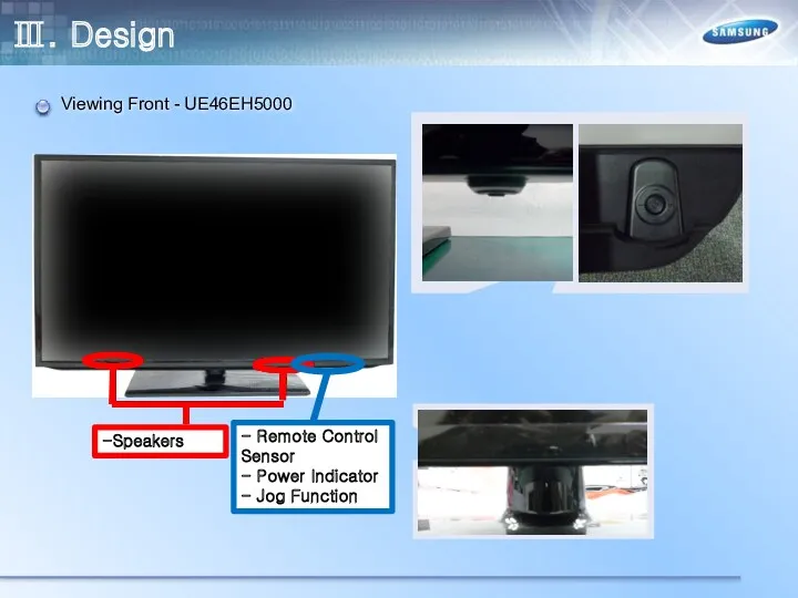
Viewing Front - UE46EH5000
-Speakers
- Remote Control Sensor
- Power Indicator
- Jog Function
Ⅲ. Design
Viewing Front - UE46EH5000
-Speakers
- Remote Control Sensor
- Power Indicator
- Jog Function
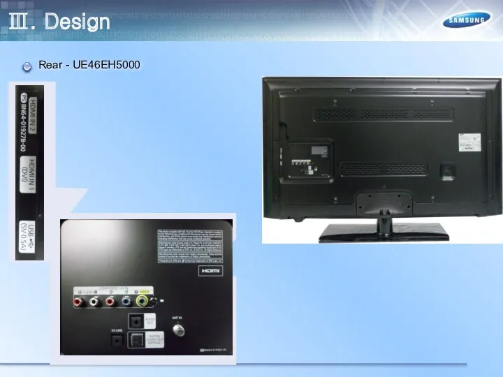
Ⅲ. Design
Rear - UE46EH5000
Ⅲ. Design
Rear - UE46EH5000
Ⅲ. Design
Viewing Front – UE19ES4000
-Speakers
- Remote Control Sensor
- Power Indicator
- Jog Function
Ⅲ. Design
Viewing Front – UE19ES4000
-Speakers
- Remote Control Sensor
- Power Indicator
- Jog Function

Ⅲ. Design
Rear – UE19ES4000
Ⅲ. Design
Rear – UE19ES4000
Ⅲ. Design
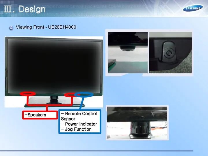
Viewing Front - UE26EH4000
-Speakers
- Remote Control Sensor
- Power Indicator
- Jog Function
Ⅲ. Design
Viewing Front - UE26EH4000
-Speakers
- Remote Control Sensor
- Power Indicator
- Jog Function
Ⅲ. Design
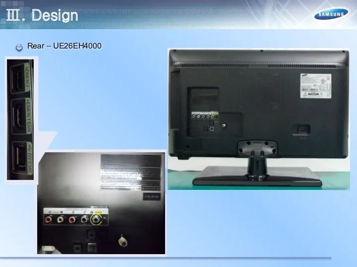
Rear – UE26EH4000
Ⅲ. Design
Rear – UE26EH4000
Ⅲ. Design
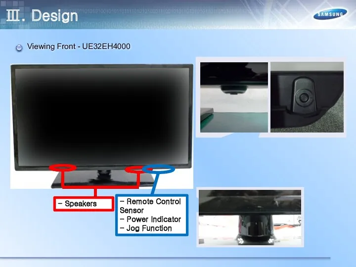
Viewing Front - UE32EH4000
- Speakers
- Remote Control Sensor
- Power Indicator
- Jog Function
Ⅲ. Design
Viewing Front - UE32EH4000
- Speakers
- Remote Control Sensor
- Power Indicator
- Jog Function
Ⅲ. Design
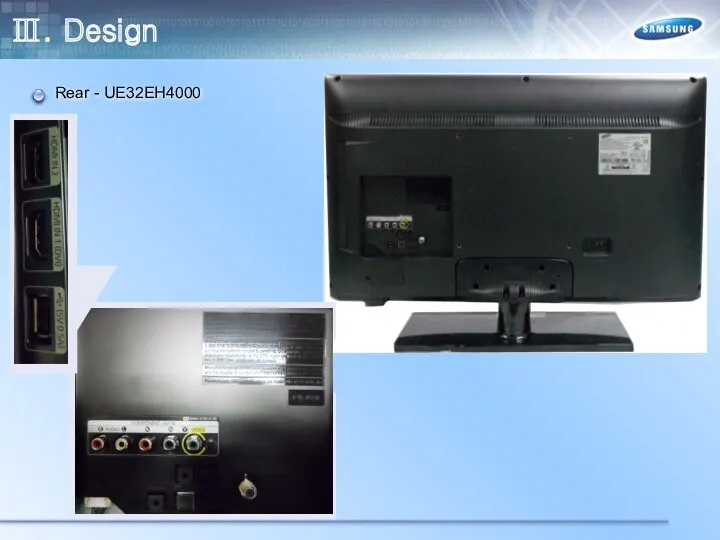
Rear - UE32EH4000
Ⅲ. Design
Rear - UE32EH4000
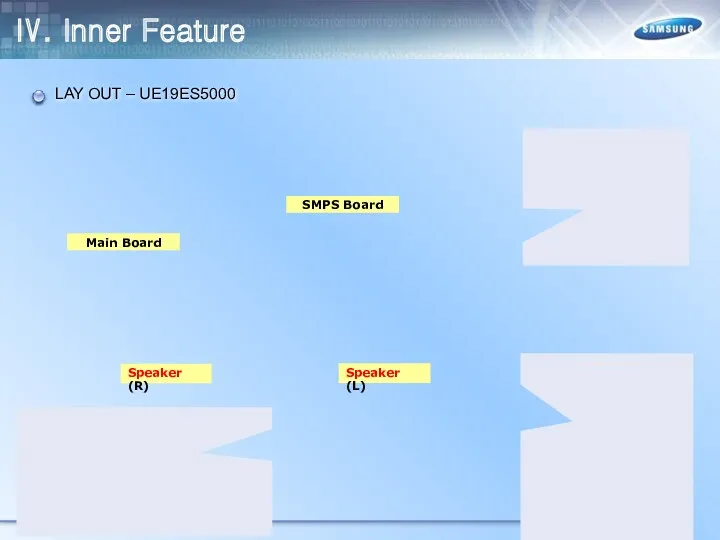
Ⅳ. Inner Feature
LAY OUT – UE19ES5000
Main Board
SMPS Board
Speaker (R)
Speaker (L)
Ⅳ. Inner Feature
LAY OUT – UE19ES5000
Main Board
SMPS Board
Speaker (R)
Speaker (L)
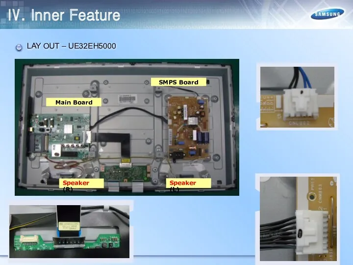
Ⅳ. Inner Feature
LAY OUT – UE32EH5000
Main Board
SMPS Board
Speaker (R)
Speaker (L)
Ⅳ. Inner Feature
LAY OUT – UE32EH5000
Main Board
SMPS Board
Speaker (R)
Speaker (L)
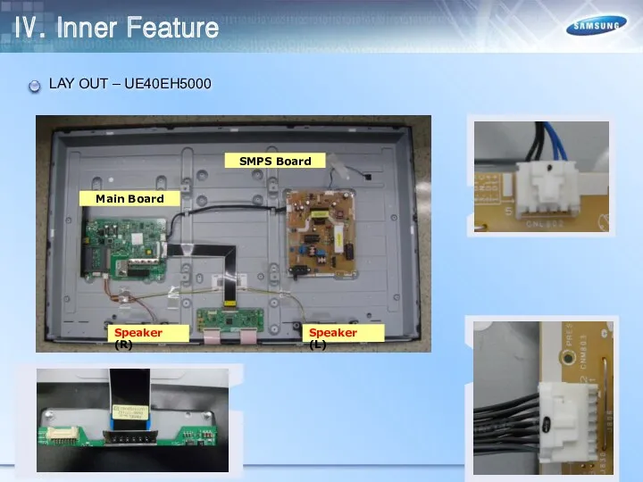
Ⅳ. Inner Feature
LAY OUT – UE40EH5000
Main Board
SMPS Board
Speaker (R)
Speaker (L)
Ⅳ. Inner Feature
LAY OUT – UE40EH5000
Main Board
SMPS Board
Speaker (R)
Speaker (L)
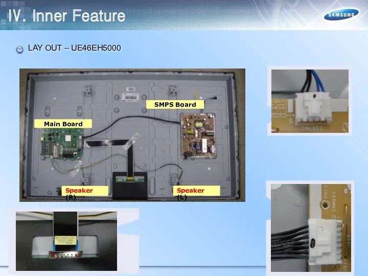
Ⅳ. Inner Feature
LAY OUT – UE46EH5000
Main Board
SMPS Board
Speaker (R)
Speaker (L)
Ⅳ. Inner Feature
LAY OUT – UE46EH5000
Main Board
SMPS Board
Speaker (R)
Speaker (L)
Ⅳ. Inner Feature
LAY OUT – UE19ES4000
Main Board
SMPS Board
Speaker (R)
Speaker (L)
Ⅳ. Inner Feature
LAY OUT – UE19ES4000
Main Board
SMPS Board
Speaker (R)
Speaker (L)

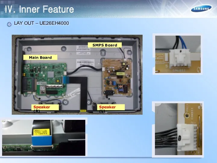
Ⅳ. Inner Feature
Main Board
SMPS Board
Speaker (R)
Speaker (L)
LAY OUT – UE26EH4000
Ⅳ. Inner Feature
Main Board
SMPS Board
Speaker (R)
Speaker (L)
LAY OUT – UE26EH4000
Main Board
SMPS Board
Speaker (R)
Speaker (L)
Ⅳ. Inner Feature
LAY OUT – UE32EH4000
Main Board
SMPS Board
Speaker (R)
Speaker (L)
Ⅳ. Inner Feature
LAY OUT – UE32EH4000
Ⅳ. Inner Feature
Wiring Diagram
Ⅳ. Inner Feature
Wiring Diagram
Ⅳ. Inner Feature
RESET TREE
SEMS 23
(Mstar X9)
SMPS
Standby
B+ Power
SW_POWER
POWER_DET
PANEL
SW_PVCC
MICOM
(WT61P802)
SW_INVERTER
RT9824
(Reset IC)
MICOM_nRESET
SYS_HRESET
RT9818_42PV
(Reset IC)
Ⅳ. Inner Feature
RESET TREE
SEMS 23
(Mstar X9)
SMPS
Standby
B+ Power
SW_POWER
POWER_DET
PANEL
SW_PVCC
MICOM
(WT61P802)
SW_INVERTER
RT9824
(Reset IC)
MICOM_nRESET
SYS_HRESET
RT9818_42PV
(Reset IC)
Ⅳ. Inner Feature
I2C
SEMS23
(MSTAR X9)
UART_RX2/GPIO44 UART_TX2/GPIO43
DDCR_CK DDCR_DA
AT24C256
(0xA0)
SCL_EEPROM SDA_EEPROM
TUNER
(0xC0)
SCL_TUNER SDA_TUNER
TCON_SCL TCON_SDA
PANEL
NTP7412S
(0x54)
AMP_SCL AMP_SDA
PC_DDC
HDMI2_DDC
HDMI2_SCL_DDC HDMI2_SDA_DDC
HDMI1_DDC
SCL_DOWN
Ⅳ. Inner Feature
I2C
SEMS23
(MSTAR X9)
UART_RX2/GPIO44 UART_TX2/GPIO43
DDCR_CK DDCR_DA
AT24C256
(0xA0)
SCL_EEPROM SDA_EEPROM
TUNER
(0xC0)
SCL_TUNER SDA_TUNER
TCON_SCL TCON_SDA
PANEL
NTP7412S
(0x54)
AMP_SCL AMP_SDA
PC_DDC
HDMI2_DDC
HDMI2_SCL_DDC HDMI2_SDA_DDC
HDMI1_DDC
SCL_DOWN
Ⅳ. Inner Feature
POWER TREE
Ⅳ. Inner Feature
POWER TREE
Ⅳ. Inner Feature
POWER TREE
Ⅳ. Inner Feature
POWER TREE
Ⅳ. Inner Feature
Main Board Layout
Ⅳ. Inner Feature
Main Board Layout
Ⅳ. Inner Feature
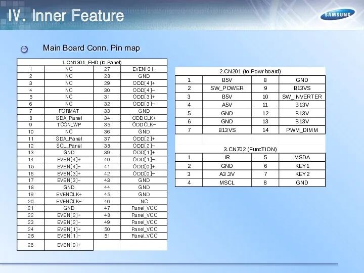
Main Board Conn. Pin map
Ⅳ. Inner Feature
Main Board Conn. Pin map
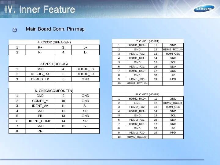
Ⅳ. Inner Feature
Main Board Conn. Pin map
Ⅳ. Inner Feature
Main Board Conn. Pin map
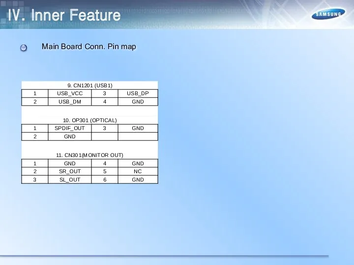
Ⅳ. Inner Feature
Main Board Conn. Pin map
Ⅳ. Inner Feature
Main Board Conn. Pin map
Ⅳ. Inner Feature
Main Board Conn. Pin map
Ⅳ. Inner Feature
Main Board Conn. Pin map
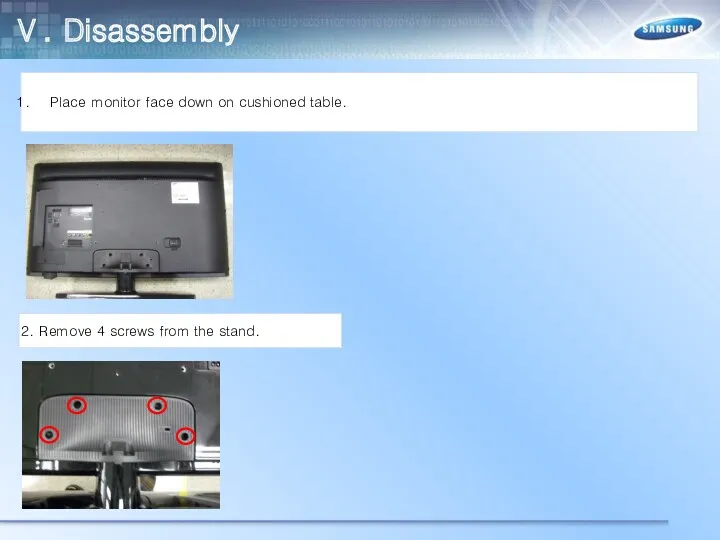
Ⅴ. Disassembly
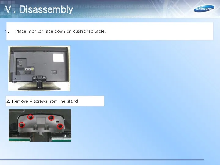
Place monitor face down on cushioned table.
2. Remove 4 screws from
Ⅴ. Disassembly
Place monitor face down on cushioned table.
2. Remove 4 screws from
Ⅴ. Disassembly
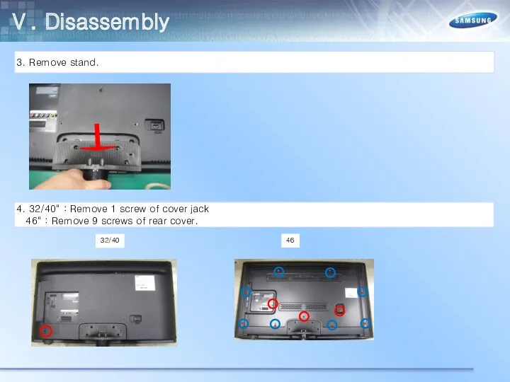
3. Remove stand.
4. 32/40" : Remove 1 screw of cover jack
Ⅴ. Disassembly
3. Remove stand.
4. 32/40" : Remove 1 screw of cover jack
Ⅴ. Disassembly
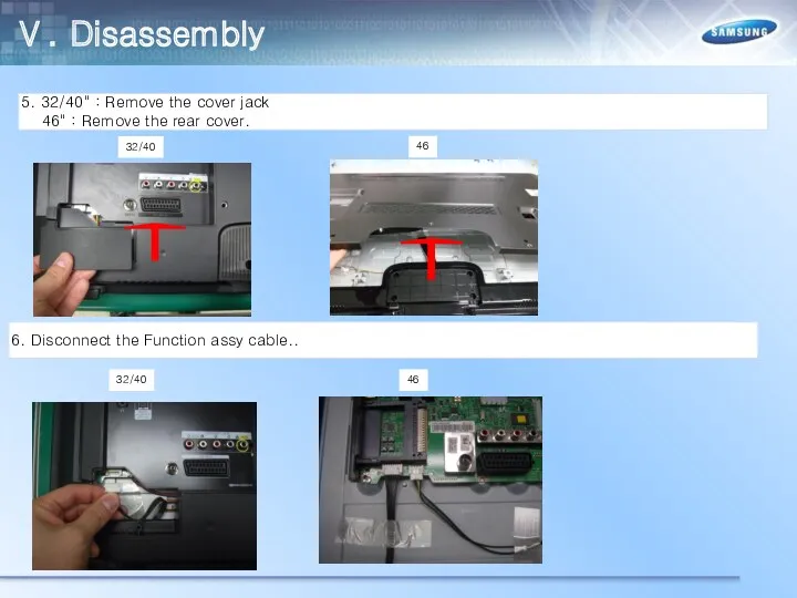
5. 32/40" : Remove the cover jack
46" : Remove the
Ⅴ. Disassembly
5. 32/40" : Remove the cover jack
46" : Remove the
Ⅴ. Disassembly
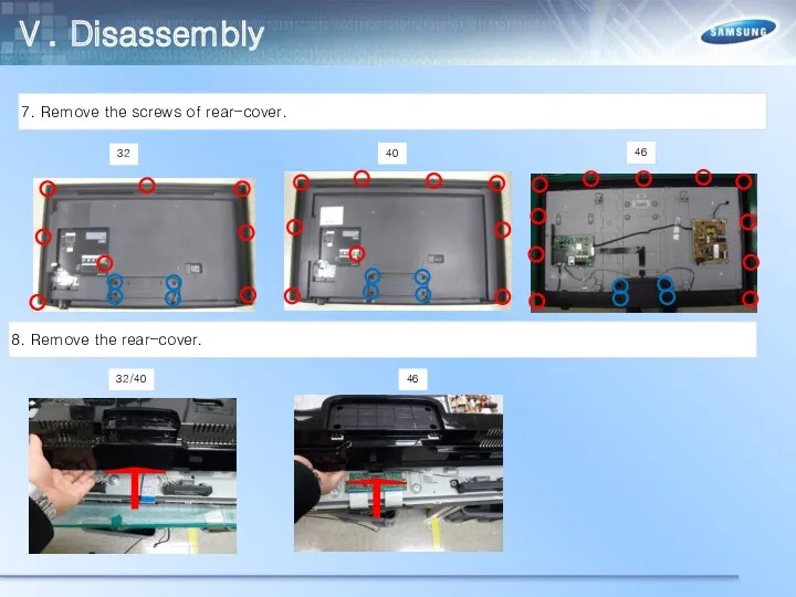
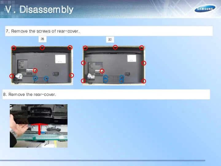
7. Remove the screws of rear-cover.
8. Remove the rear-cover.
40
32
46
46
32/40
Ⅴ. Disassembly
7. Remove the screws of rear-cover.
8. Remove the rear-cover.
40
32
46
46
32/40
Ⅴ. Disassembly
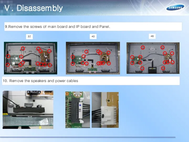
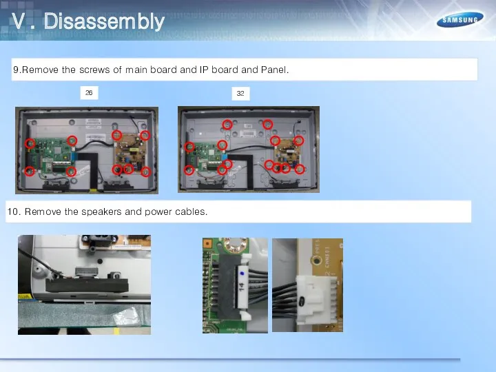
9.Remove the screws of main board and IP board and Panel.
10.
Ⅴ. Disassembly
9.Remove the screws of main board and IP board and Panel.
10.
Ⅴ. Disassembly
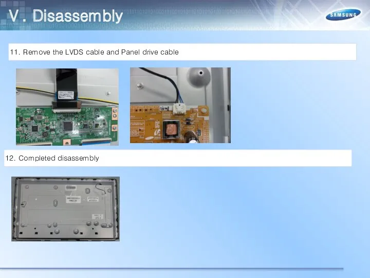
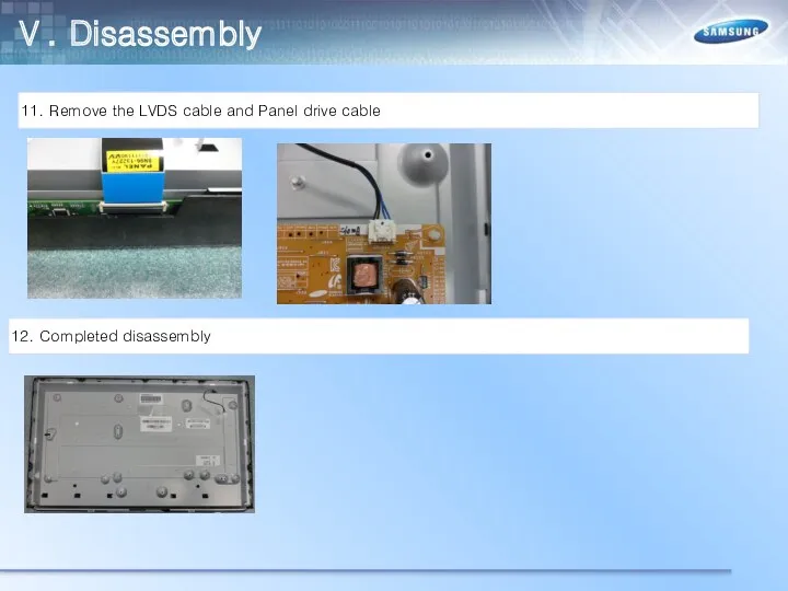
11. Remove the LVDS cable and Panel drive cable
12. Completed disassembly
Ⅴ. Disassembly
11. Remove the LVDS cable and Panel drive cable
12. Completed disassembly
Ⅴ. Disassembly
Place monitor face down on cushioned table.
2. Remove 4 screws from
Ⅴ. Disassembly
Place monitor face down on cushioned table.
2. Remove 4 screws from
Ⅴ. Disassembly
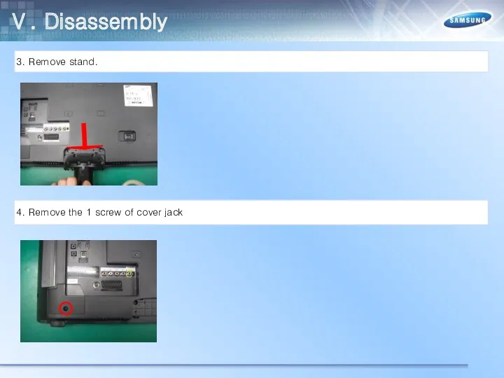
3. Remove stand.
4. Remove the 1 screw of cover jack
Ⅴ. Disassembly
3. Remove stand.
4. Remove the 1 screw of cover jack
Ⅴ. Disassembly
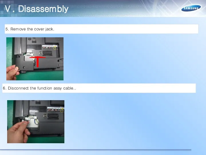
5. Remove the cover jack.
6. Disconnect the function assy cable..
Ⅴ. Disassembly
5. Remove the cover jack.
6. Disconnect the function assy cable..
Ⅴ. Disassembly
7. Remove the screws of rear-cover.
8. Remove the rear-cover.
32
26
Ⅴ. Disassembly
7. Remove the screws of rear-cover.
8. Remove the rear-cover.
32
26
Ⅴ. Disassembly
9.Remove the screws of main board and IP board and Panel.
10.
Ⅴ. Disassembly
9.Remove the screws of main board and IP board and Panel.
10.
Ⅴ. Disassembly
11. Remove the LVDS cable and Panel drive cable
12. Completed disassembly
Ⅴ. Disassembly
11. Remove the LVDS cable and Panel drive cable
12. Completed disassembly
Ⅴ. Disassembly(PTC)
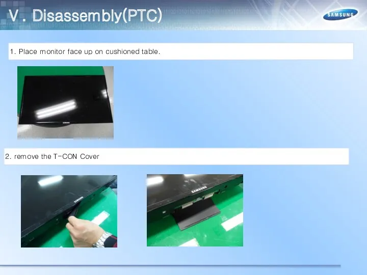
1. Place monitor face up on cushioned table.
2. remove the T-CON
Ⅴ. Disassembly(PTC)
1. Place monitor face up on cushioned table.
2. remove the T-CON
Ⅴ. Disassembly(PTC)
3. first spread the PTC upper
4. Spread the both sides of
Ⅴ. Disassembly(PTC)
3. first spread the PTC upper
4. Spread the both sides of
Ⅴ. Disassembly(PTC)
5. Apart left and right sides of PTC
6. Raise up the
Ⅴ. Disassembly(PTC)
5. Apart left and right sides of PTC
6. Raise up the
Ⅴ. Disassembly(PTC)
7. Disassembly is complete.
Ⅴ. Disassembly(PTC)
7. Disassembly is complete.
Ⅴ. Reassembly(PTC)
1. Cover the PTC bottom
2. Combine the hook of left and
Ⅴ. Reassembly(PTC)
1. Cover the PTC bottom
2. Combine the hook of left and
Ⅴ. Disassembly(PTC)
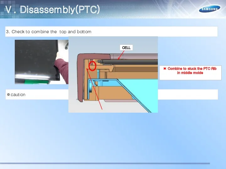
3. Check to combine the top and bottom
※caution
※ Combine to stuck
Ⅴ. Disassembly(PTC)
3. Check to combine the top and bottom
※caution
※ Combine to stuck
Ⅴ. Disassembly(PTC)
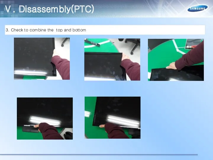
3. Check to combine the top and bottom
Ⅴ. Disassembly(PTC)
3. Check to combine the top and bottom
Ⅴ. Disassembly(PTC)
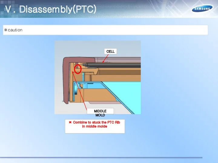
※caution
※ Combine to stuck the PTC Rib in middle molde
Ⅴ. Disassembly(PTC)
※caution
※ Combine to stuck the PTC Rib in middle molde
Ⅴ. Disassembly(PTC)
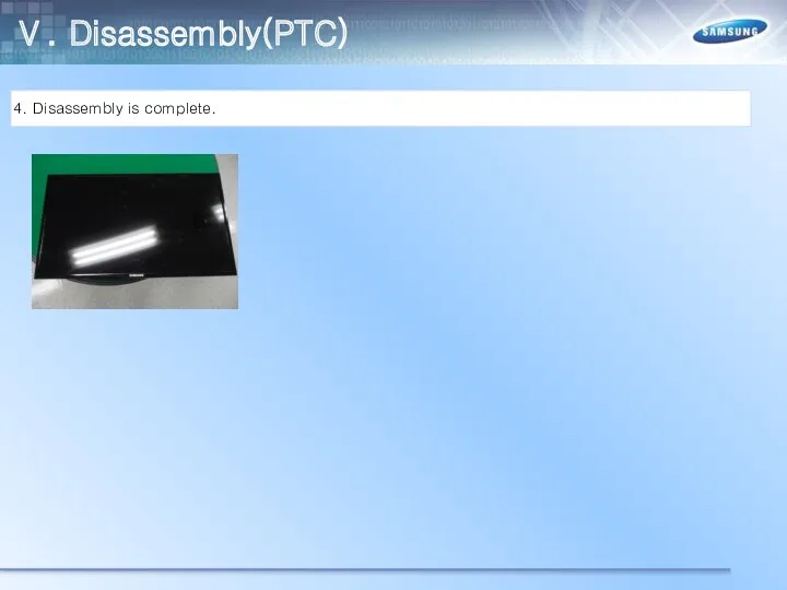
4. Disassembly is complete.
Ⅴ. Disassembly(PTC)
4. Disassembly is complete.
Ⅵ. Trouble Shooting
Check List for Initial operation
Ⅵ. Trouble Shooting
Check List for Initial operation
Ⅵ. Trouble Shooting
No power AND No Video
Ⅵ. Trouble Shooting
No power AND No Video
Ⅵ. Trouble Shooting
No power AND No Video
Ⅵ. Trouble Shooting
No power AND No Video
Ⅵ. Trouble Shooting
No power AND No Video
Ⅵ. Trouble Shooting
No power AND No Video
Ⅵ. Trouble Shooting
RS232C code
Ⅵ. Trouble Shooting
RS232C code
Ⅵ. Trouble Shooting
Calibration
Ⅵ. Trouble Shooting
Calibration
Ⅵ. Trouble Shooting
Calibration
Ⅵ. Trouble Shooting
Calibration
Ⅵ. Trouble Shooting
White Balance
Ⅵ. Trouble Shooting
White Balance
Ⅵ. Trouble Shooting
How to check the SW version
Ⅵ. Trouble Shooting
How to check the SW version
Ⅵ. Trouble Shooting
How to check the SW version
Ⅵ. Trouble Shooting
How to check the SW version
Ⅵ. Trouble Shooting
USB Download
Ⅵ. Trouble Shooting
USB Download
Ⅵ. Trouble Shooting
USB Download
Ⅵ. Trouble Shooting
USB Download
Ⅵ. Trouble Shooting
USB Download
Ⅵ. Trouble Shooting
USB Download
 Почему идет дождь и дует ветер
 Психологическая готовность ребенка к обучению в школе
 Classroom language
 Буынның түрлері, құрылысы. Мозайканы құрастыру
 Учимся писать посты
 tovka 2 2
 Қатты және жұмсақ таңдай кілегей қабығының анатомо-топографиялық ерекшеліктері
 Геометрические задачи С4, по материалам ЕГЭ. Подобие треугольников
 Полное снятие блокады Ленинграда
 Итоговая презентация к проекту на тему: Весна. Праздник Пасхи
 Дополнительные материалы к экзамену. Реальный сектор экономики
 Основы почвоведения. Факторы и процессы почвообразования
 Развитие музыкальности старших дошкольников на основе применения народной музыки
 Цель водоподготовки для ТЭЦ. Качество обессоленной воды для ТЭЦ. Достоинства и недостатки мембранных технологий
 ФГОС
ФГОС Устройство персонального компьютера
 Статья- Ранее воспитание детей-главная цель в развитии ребенка.
 Диагностика беременности
 Монтаж осветительных щитков
 Prezentatsia
 Научная работа, представляемая на Республиканский конкурс НИРС: структура и требования к оформлению
 Предметная и проблемная область
 Японское чудо
 Зерномучные товары. Мука
 Ортопедиялық стоматология пропедевтикасының модулі
 Мы рисуем море
 Таблица сложения. Тренажёр Игра в футбол
 Гидроизоляция с Пенетрон