- MP C3003-6003. Service master update training Ricoh Academy Europe

Содержание
- 2. Objectives After completing this training you should be: Able to install the MP C3003 series in
- 3. Requirements Metis-C1 with Cheetah operation panel. Windows PC. Field Service Manual. This presentation.
- 4. Pre-requisites and exam Before starting this training you must already have followed the My-Ricoh training for:
- 5. Module overview 1. Introduction 2. Installation 3. Maintenance 4. Detailed Section Descriptions 5. Troubleshooting 6. Android
- 6. 1. Introduction
- 7. Metis-C1 The Metis-C1 is the successor model of the Athena, Apollon and Diana series. The Metis-C1
- 8. Different models ARDF SPDF Cheetah panel Conventional panel
- 9. Difference between the models Fusing unit: Fusing lamps and shield is different between a/b models and
- 10. Yield and consumables Toner cartridges: Metis-C1a/b: K: 28k prints/bottle YMC: 18k prints/bottle Metis-C1c/d/e: K: 31k prints/bottle
- 11. Targets & reliability Average Print Volume (APV): Metis-C1a: 5k/month Metis-C1b: 7k/month Metis-C1c: 10k/month Metis-C1d: 12k/month Metis-C1e:
- 12. 2. Installation
- 13. Important 1 of the changed items from the predecessor is the total weight of the machines.
- 14. Hardware Installation Basically, this is very simple. Remove packing materials. Remove the seals from the PCDUs
- 15. Lifting the machine Always lift the machine with the handles at the bottom. When shipped from
- 16. Removing the PCDU seals Each PCDU [A] has a seal [B] that must be removed during
- 17. Front covers PCDU’s & ITB unit Covers are not installed on the machine when it is
- 18. ITB levers Two levers: Move them down for normal operation. Move them up when you want
- 19. Toner bottles Toner bottles The shape of the bottles is different from previous models. You must
- 20. ARDF To prevent original jams when feeding thin originals the slider in the exit can be
- 21. Boards (SPDF/ARDF) An additional IPU board is installed on the SPDF model. The BCU board is
- 22. Internal finisher The punch unit for this finisher must be installed first before you install the
- 23. Finisher SR3140 (D687) Only for D687: Two stabilizers are included as accessories. They must be attached
- 24. Imageable area extension unit You need this option for printing on 320mm width paper. During installation:
- 25. What can happen? SP setting is the normal setting (SRA3 paper not supported) and the optional
- 26. Enter SP Mode The number sequence to enter SP mode is changed.
- 27. SD Card Slots [A]: SD card slot 1 (option slot) [B]: SD card slot 2 (service
- 28. SD Card Merging In former models there are some SD card options that can’t be merged.
- 29. Embedded OCR (Searchable PDF) Do the installation procedure according to the field service manual. SP 5-878-004
- 30. After Installing the Machine and All Options After you have finished installing the machine, back up
- 31. 3. Maintenance
- 32. PM Parts PCDU PCU-K: 400k Development Unit – K: 600k Transfer ITB Unit: 600k ITB Cleaning
- 33. Yield Parts Development Unit – CMY: 600k PCU – CMY: 270k ARDF Feed Belt, Pick-up Roller,
- 34. Replacing a PM Part Execute the SP for forced detection of a new part. See the
- 35. SP Modes before PM part replacement SP3-701-002 PCU Bk SP3-701-003 Dev Bk SP3-701-025 PCU C SP3-701-026
- 36. New Function: PM Counter New features on the PM counter display allow you to see the
- 37. New Function: PM Counter For some machines this function was already available. SP Mode initial screen
- 38. PM counter By pressing the PM Counter button, you go into the PM Parts menu of
- 39. All PM parts list
- 40. Counter clear for parts exceeding target yield
- 41. Parts list for PM yield indicator
- 42. Clear all PM settings
- 43. Parts exceeding target yield
- 44. Counter list print out
- 45. Estimated Usage Rate/Remain Days
- 46. Commissioning Status Report Print
- 47. Page counter and Running distance PM Counter Running Distance A B C You should replace the
- 48. Page Counter and Running Distance PM parts yield is based on the page counter when the
- 49. Estimated Value Display
- 50. Estimated Usage Rate Display Displays the larger of these two values: Page counter (SP7-954-xxx) and running
- 51. Estimated Remaining Days Display Displays the smaller of these two values: Page counter (SP7-951-XXX) and running
- 52. Commissioning Status Report You can print the Status Report to check the machine status. SP7-403-001~010 SC
- 53. 4. Detailed Section Descriptions
- 54. Chapter Overview 4.1 Machine Overview 4.2 Scanner 4.3 Laser Unit 4.4 PCDU 4.5 Toner Supply 4.6
- 55. 4.1 Machine Overview
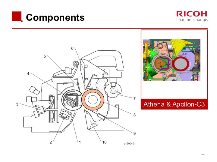
- 56. Components Athena & Apollon-C3
- 57. Drive Components Athena & Apollon-C3
- 58. Differences from Predecessors: Drive
- 59. Drive Components Paper Feed Motor Transport Motor Registration Motor Paper Transfer Contact Motor Fusing Motor Development
- 60. Paper Path (1/3) Athena & Apollon-C3
- 61. Paper Path (2/3) Athena & Apollon-C3 Internal Finisher not available.
- 62. Paper Path (3/3)
- 63. Cooling Metis-C1 a/b 8 Fan’s are used for cooling. Front Rear PCBs
- 64. Cooling Metis-C1 c/d/e 11 Fan’s are used for cooling. Front Rear PCBs
- 65. Function of fans
- 66. Cooling Notes Toner supply cooling duct: The shape of the duct for Met-C1c/d/e is different from
- 67. Differences from Predecessors: Electrical Components
- 68. Locations of PCBs Inside the Controller Box IPU Sub (only if an SPDF is present) IPU
- 69. Locations of PCBs Behind the Controller Box HVP_TTS Imaging IOB
- 70. Locations of PCBs Inside the Power Box PSU (AC controller board) PSU (DC Power) PSU Cooling
- 71. Locations of PCBs Behind the Power Box HVP_CB Paper Transport IOB
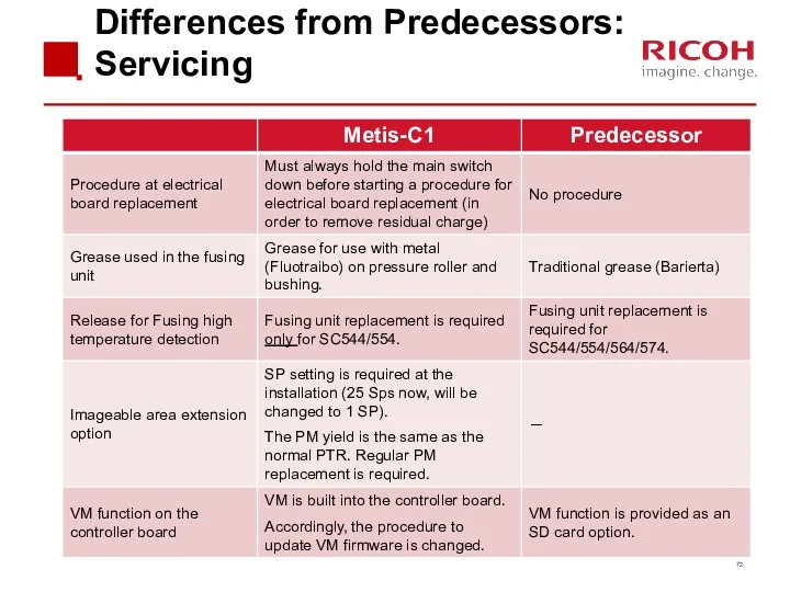
- 72. Differences from Predecessors: Servicing
- 73. Switch off procedure Push the power switch [A] on the machine. Wait until the shut-off screen
- 74. Starting the machine again To start the machine, press the main power switch. If you press
- 75. Forced Shutdown In case normal shutdown does not complete, the machine has a forced shutdown function.
- 76. Replacement of parts Some of the covers have tabs on them which break easily. The procedures
- 77. LCD Panel (1/2) LCD panels from two different vendors are used. Depending on which type is
- 78. LCD Panel (2/2) How to determine the correct type to install? There are three labels on
- 79. Replacing NVRAMs on the Controller Board Make sure that the NVRAMs are installed in the correct
- 80. 4.2 Scanner
- 81. Differences from Predecessors: Scanner unit
- 82. Scanner Unit
- 83. DF exposure glass Originals may cause streaks on the exposure glass. To prevent these streaks non-contact
- 84. Dust Detection – Overview This function checks the ADF exposure glass for dust that can cause
- 85. Dust Detection (SP 4-020) SP 4-020-001: Enable/disable (default – disabled) SP 4-020-002: Sensitivity adjustment SP 4-020-003:
- 86. Dust Detection - Action Taken When dust detection determines that dust exists, the scan point shifts
- 87. Laser Unit
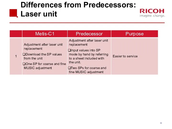
- 88. Differences from Predecessors: Laser unit
- 89. Overview
- 90. Components There are two LD drive boards. M150, M149, M148: 2 beams/colour M147, M146: 1 beam/colour
- 91. Skew Adjustment The 2nd mirrors for C, M, and Y have a motor to adjust the
- 92. Replacing the Laser Unit After installing the new unit: Disconnect the skew correction motor harness. Execute
- 93. PCDU
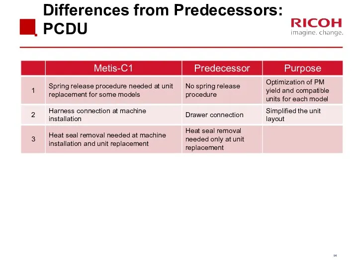
- 94. Differences from Predecessors: PCDU
- 95. Layout Athena & Apollon-C3
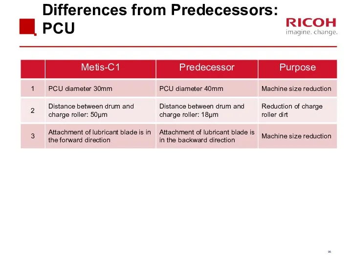
- 96. Differences from Predecessors: PCU
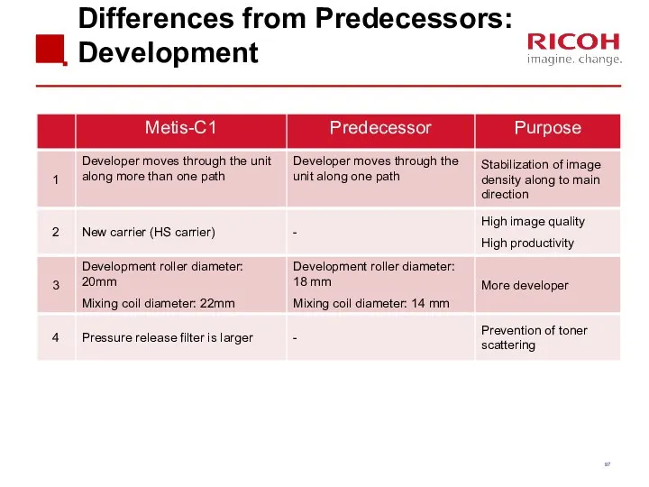
- 97. Differences from Predecessors: Development
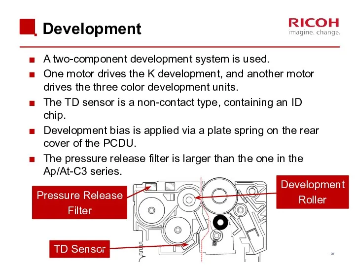
- 98. Development A two-component development system is used. One motor drives the K development, and another motor
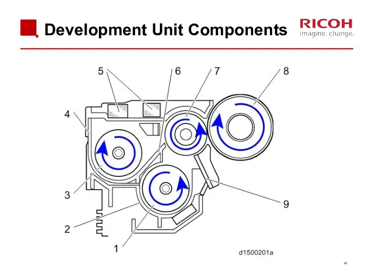
- 99. Development Unit Components
- 100. Replacing Note for PCDU or PCU Before replacing a PCU or PCDU, set SP3-701 to "1"
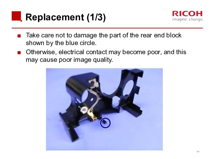
- 101. Replacement (1/3) Take care not to damage the part of the rear end block shown by
- 102. Replacement (2/3) If you join the drum unit and development unit while pressing the charge roller,
- 103. Replacement (3/3) To check that toner lines do not appear, turn the drum in the direction
- 104. Replacing the PCDU / PCU on a D149 or D150 An additional procedure is required when
- 105. Replacing the PCDU or PCU on a D149 or D150 1. Remove the seal 2. Move
- 106. Toner Supply
- 107. Differences from Predecessors: Toner Supply
- 108. Layout Athena & Apollon-C3
- 109. From bottle to sub hopper (1/2) When toner end is detected, the toner in the bottle
- 110. From bottle to sub hopper (2/2) To prevent toner from remaining, a spring [A] in the
- 111. Toner Near-end Detection The machine estimates the amount of toner remaining in the cartridge using two
- 112. ‘Estimated Toner Near-end’ If the amount of remaining toner falls below a certain limit (SP3-110-001 to
- 113. ‘Definite Toner Near-end’ If the amount of remaining toner falls below a certain limit (SP3-120-001 to
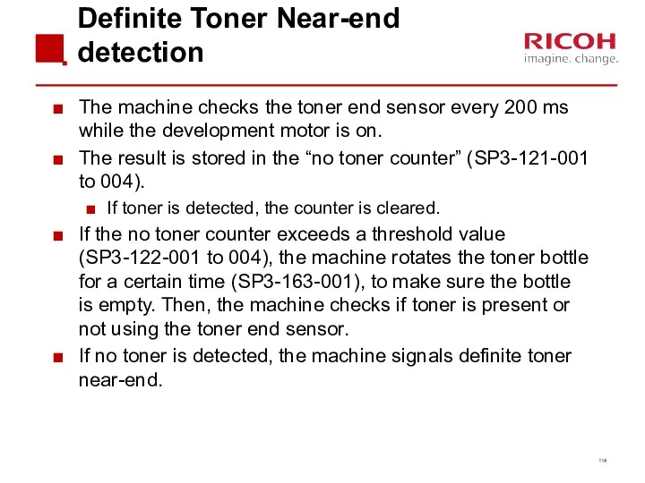
- 114. Definite Toner Near-end detection The machine checks the toner end sensor every 200 ms while the
- 115. Toner End Detection After toner near-end is detected, the machine signals toner end if one of
- 116. Paper Feed
- 117. Differences from Predecessors: Paper Feed
- 118. Differences from Predecessors: By-pass
- 119. Differences from Predecessors: Optional PFU
- 120. Differences from Predecessors: Tandem LCT
- 121. Differences from Predecessors: Side LCT
- 122. Overview
- 123. Drive (1) The paper feed motor(1) drives the pick-up and feed rollers in both trays. The
- 124. Bottom Plate Lift When the tray is removed, the coupling is released, and the base plate
- 125. Remaining Paper Detection – Trays 1 and 2 The lift motor assembly contains two height sensors,
- 126. Paper Dust Removal A mylar sheet contacts the registration idle roller, and sends paper dust to
- 127. Tray Pull-in Mechanism The tray is pulled in by a one-way clutch and spring mechanism in
- 128. Paper Jam LED (Metis-C1c/d/e only) When a Z jam or a B jam occurs, the remaining
- 129. Paper thickness & Double-feed Detection (Metis-C1e only) If the wrong paper weight setting is used the
- 130. Principle On the left, normal paper is being fed. On the right, thick paper is being
- 131. Inside Paper Thickness Sensor There is an encoder inside the sensor to measure the angle of
- 132. Double-feed Detection The machine compares the thickness of the current sheet with the previous sheet. If
- 133. Sensor Tolerance For each paper weight setting that is applied to a tray, there is a
- 134. Paper Thickness Detection Other Points Sensor error detection The paper thickness sensor output value is measured
- 135. By-pass Tray Components
- 136. By-pass Tray Size Detection The width sensor is a rotary switch, connected through gears and a
- 137. By-pass Tray Side Fence Contact Mechanism (D150 only) This mechanism adjusts the positions of the side
- 138. Side Fence Contact Mechanism A sensor is attached below the side fence. It converts a magnetic
- 139. Exercise Remove the 1st and 2nd paper feed unit and remove on the D150 the paper
- 140. Image Transfer
- 141. Differences from Predecessors: Image Transfer
- 142. Overview Image Transfer Roller ITB Drive Roller Paper Transfer Roller ITB Cleaning Unit
- 143. Drive The K drum motor drives the image transfer belt (ITB). The motor contains a monitoring
- 144. Power Supply Power is supplied to the image transfer rollers and the ITB drive roller from
- 145. ITB Contact and Release The motor is also the toner supply motor for magenta. The direction
- 146. ITB Cleaning The cleaning unit is on top of the ITB unit. A counter blade is
- 147. Paper Transfer Roller (PTR) Charge applied to the ITB drive roller transfers toner from the ITB
- 148. PTR Contact and Release During Process control or MUSIC the PTR is moved away from the
- 149. ID Sensors Three ID sensors are used for process control. The sensors are located above the
- 150. Real Time Process Control Image Area Patches Patches
- 151. Replacement ITB Lever Position Before you remove or insert the image transfer belt unit: Open the
- 152. Replacement ITB Cleaning Unit When removing the ITB cleaning unit: Turn the ITB unit upside down
- 153. Replacement ID Sensors Before you replace the ID sensor, you must input the values 1-6 on
- 154. Fusing
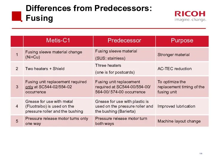
- 155. Differences from Predecessors: Fusing
- 156. Components Athena & Apollon-C3
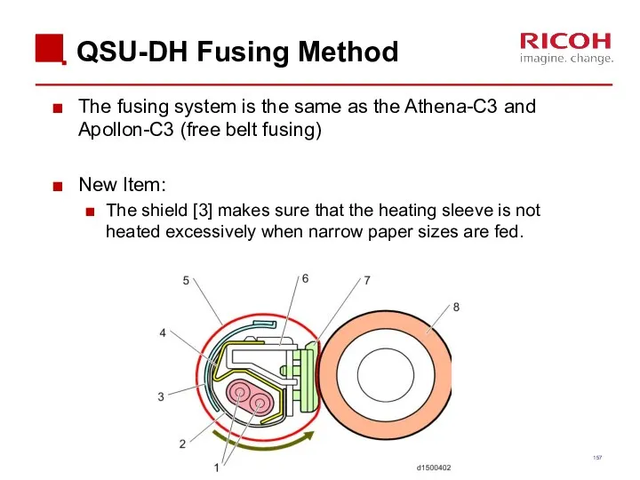
- 157. QSU-DH Fusing Method The fusing system is the same as the Athena-C3 and Apollon-C3 (free belt
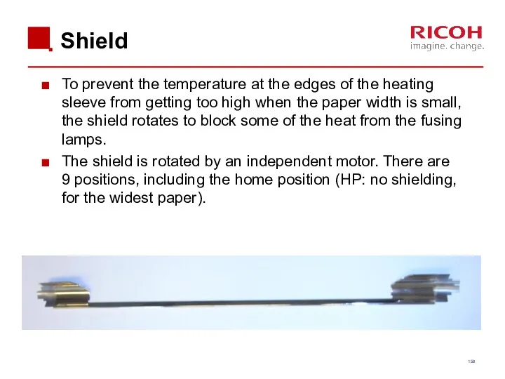
- 158. Shield To prevent the temperature at the edges of the heating sleeve from getting too high
- 159. Shield Rotation A B C D E F J I H G
- 160. Temperature Control Thermopile (edge) Thermopile (center) Heater Thermistor (edge) NC sensor (edge) NC sensor (center) Thermostat
- 161. CPM Down Control Handling Low Temperatures The central thermopile is checked at regular intervals, and if
- 162. CPM Down Control Handling High Temperatures Because the fusing unit has a low heat capacity, the
- 163. Fusing Temperature Detection The temperature is checked at regular intervals. If the temperature is above a
- 164. Paper Passage Time Depending on the paper size, it may not be possible to use a
- 165. Pressure Roller Replacement When replacing the pressure roller do not remove or adjust the pressure adjusting
- 166. Replacement Fusing Sleeve Belt Unit Do NOT touch the surface of the fusing sleeve belt. It
- 167. Installing Fusing Unit When putting the fusing unit back in the machine, fasten the screw at
- 168. Fusing Shield Motor Test Remove the fusing unit. The motor rotation is not visible when the
- 169. Hardware Detection SC Codes A new fusing unit / heating sleeve unit must be installed for
- 170. Paper Exit, Duplex
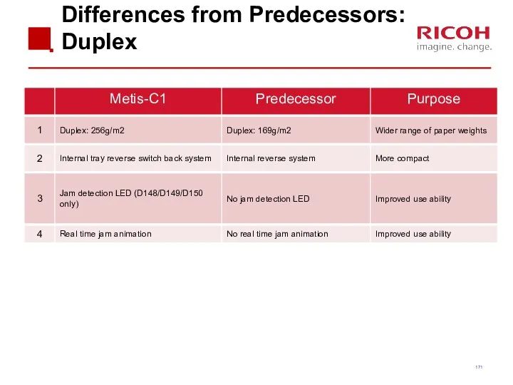
- 171. Differences from Predecessors: Duplex
- 172. Paper Exit To feed the paper to the standard exit, without duplexing, the junction gate stays
- 173. Duplex Feed Path
- 174. Duplex Feed Inverter Area
- 175. Interleaving The following items have influence on the number of sheets inside the machine: Paper length
- 176. Waste Toner Collection
- 177. Differences from Predecessors: Waste Toner
- 178. Collection Coils Waste toner from the PCU and transfer unit is collected at the front of
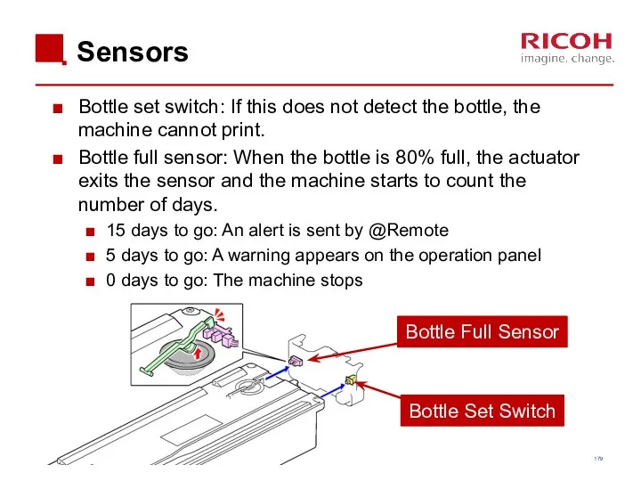
- 179. Sensors Bottle set switch: If this does not detect the bottle, the machine cannot print. Bottle
- 180. 5. Troubleshooting
- 181. Capturing the Debug Logs (1/3) Debug logs for the controller, engine, and operation panel can be
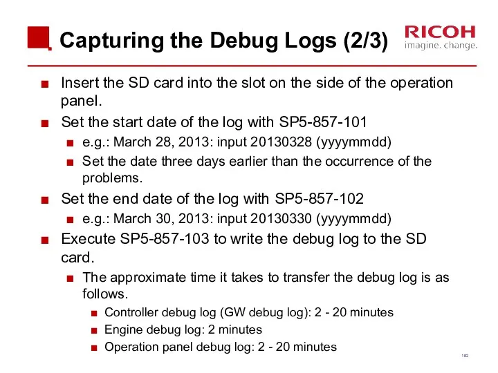
- 182. Capturing the Debug Logs (2/3) Insert the SD card into the slot on the side of
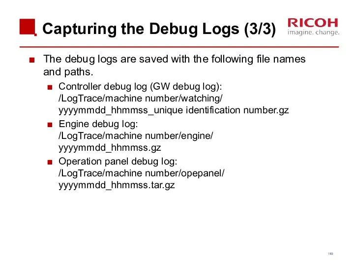
- 183. Capturing the Debug Logs (3/3) The debug logs are saved with the following file names and
- 184. 6. Android Operation Panel Smart Operation Panel Type M3 (D148)
- 185. Appearance (1/2) Home key Back key (Only used for Android Apps) Check status key Stop key
- 186. Appearance (2/2)
- 187. System Configuration
- 188. Basic information (1/3) There are two kinds of applications. 1) Android applications You can use “flick
- 189. Basic information (2/3) You can customize the Home display. You can add widgets (Toner remaining, clock,
- 190. Basic information (3/3) SC or machine status is displayed in legacy mode. There is no independent
- 191. Applications
- 192. Legacy UI on Cheetah Legacy UI will be prepared for all MFP functions, such as Copy,
- 193. Start up There are two start up displays: GW controller and Android) Android GW controller
- 194. Screen start up mode There are two modes for screen start up: Normal (Default) Low electricity
- 195. Special shut down mode There are two special shut down modes: Shut down for maintenance. When
- 196. Service Modes There are three SP modes. Machine service mode Android operation panel service mode Recovery
- 198. Скачать презентацию
Objectives
After completing this training you should be:
Able to install the MP
Objectives
After completing this training you should be:
Able to install the MP
Requirements
Metis-C1 with Cheetah operation panel.
Windows PC.
Field Service Manual.
This presentation.
Requirements
Metis-C1 with Cheetah operation panel.
Windows PC.
Field Service Manual.
This presentation.

Pre-requisites and exam
Before starting this training you must already have followed
Pre-requisites and exam
Before starting this training you must already have followed
Module overview
1. Introduction
2. Installation
3. Maintenance
4. Detailed Section Descriptions
5. Troubleshooting
6. Android Operation
Module overview
1. Introduction
2. Installation
3. Maintenance
4. Detailed Section Descriptions
5. Troubleshooting
6. Android Operation

1. Introduction
1. Introduction
Metis-C1
The Metis-C1 is the successor model of the Athena, Apollon and
Metis-C1
The Metis-C1 is the successor model of the Athena, Apollon and
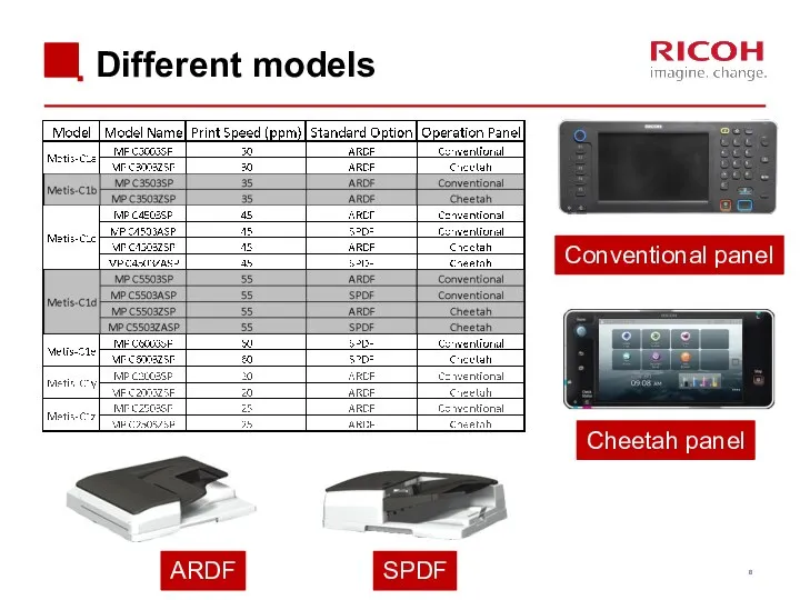
Different models
ARDF
SPDF
Cheetah panel
Conventional panel
Different models
ARDF
SPDF
Cheetah panel
Conventional panel
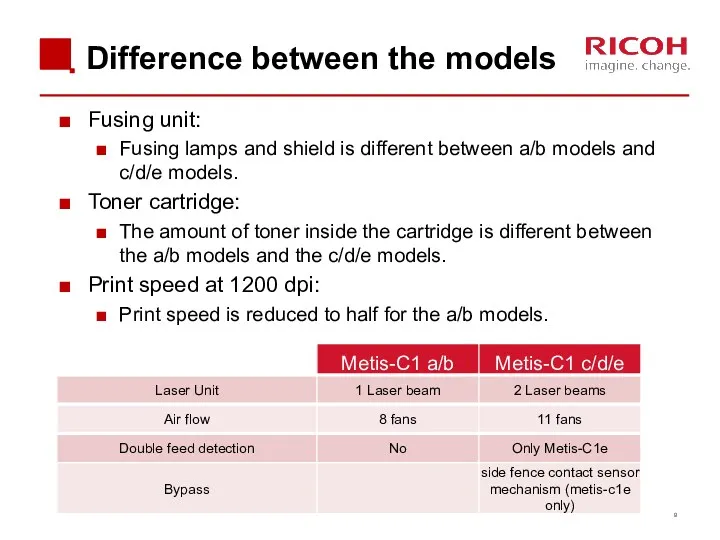
Difference between the models
Fusing unit:
Fusing lamps and shield is different
Difference between the models
Fusing unit:
Fusing lamps and shield is different
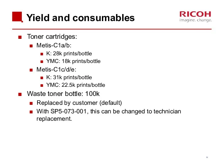
Yield and consumables
Toner cartridges:
Metis-C1a/b:
K: 28k prints/bottle
YMC: 18k prints/bottle
Metis-C1c/d/e:
K: 31k prints/bottle
YMC: 22.5k
Yield and consumables
Toner cartridges:
Metis-C1a/b:
K: 28k prints/bottle
YMC: 18k prints/bottle
Metis-C1c/d/e:
K: 31k prints/bottle
YMC: 22.5k
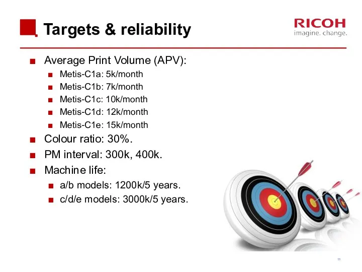
Targets & reliability
Average Print Volume (APV):
Metis-C1a: 5k/month
Metis-C1b: 7k/month
Metis-C1c: 10k/month
Metis-C1d: 12k/month
Metis-C1e: 15k/month
Colour
Targets & reliability
Average Print Volume (APV):
Metis-C1a: 5k/month
Metis-C1b: 7k/month
Metis-C1c: 10k/month
Metis-C1d: 12k/month
Metis-C1e: 15k/month
Colour
2. Installation
2. Installation
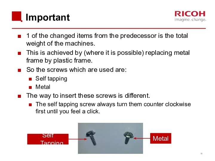
Important
1 of the changed items from the predecessor is the
Important
1 of the changed items from the predecessor is the
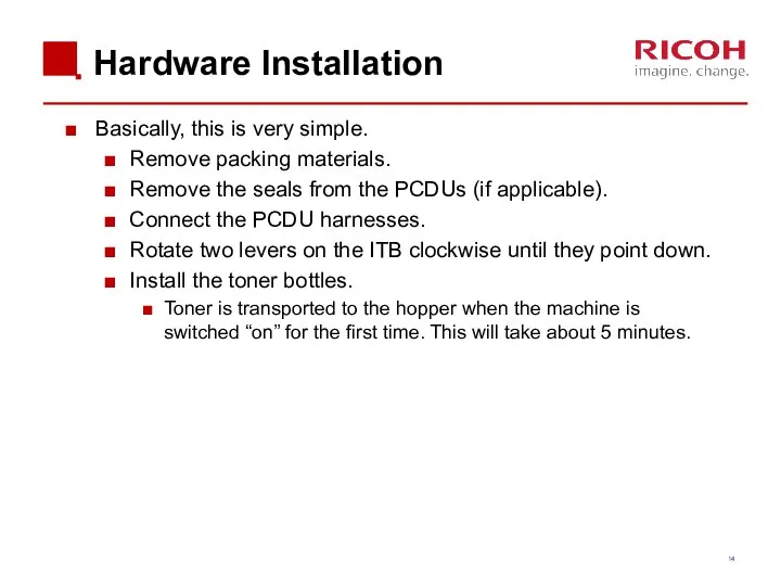
Hardware Installation
Basically, this is very simple.
Remove packing materials.
Remove the seals from
Hardware Installation
Basically, this is very simple.
Remove packing materials.
Remove the seals from
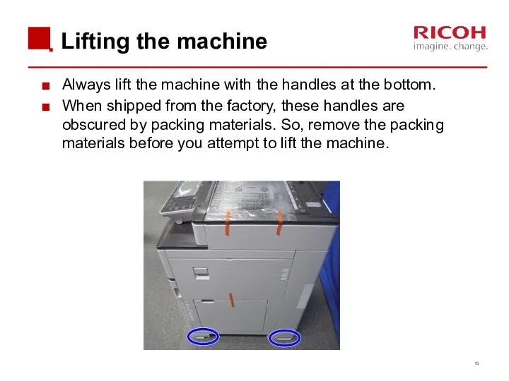
Lifting the machine
Always lift the machine with the handles at the
Lifting the machine
Always lift the machine with the handles at the
![Removing the PCDU seals Each PCDU [A] has a seal](/_ipx/f_webp&q_80&fit_contain&s_1440x1080/imagesDir/jpg/201019/slide-15.jpg)
Removing the PCDU seals
Each PCDU [A] has a seal [B] that
Removing the PCDU seals
Each PCDU [A] has a seal [B] that
Front covers PCDU’s & ITB unit
Covers are not installed on the
Front covers PCDU’s & ITB unit
Covers are not installed on the
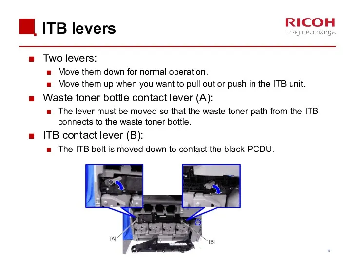
ITB levers
Two levers:
Move them down for normal operation.
Move them up when
ITB levers
Two levers:
Move them down for normal operation.
Move them up when
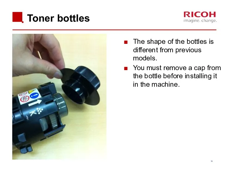
Toner bottles
Toner bottles
The shape of the bottles is different from previous
Toner bottles
Toner bottles
The shape of the bottles is different from previous
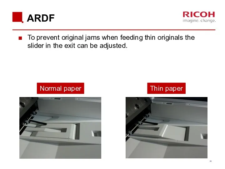
ARDF
To prevent original jams when feeding thin originals the slider in
ARDF
To prevent original jams when feeding thin originals the slider in

Boards (SPDF/ARDF)
An additional IPU board is installed on the SPDF model.
The
Boards (SPDF/ARDF)
An additional IPU board is installed on the SPDF model.
The
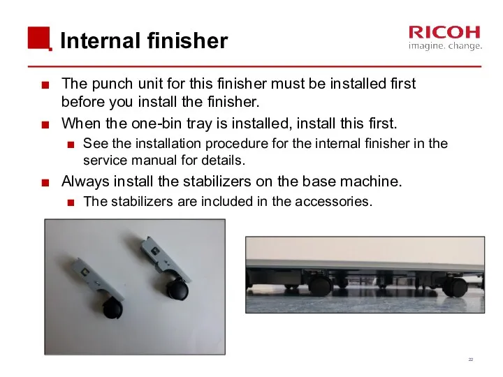
Internal finisher
The punch unit for this finisher must be installed first
Internal finisher
The punch unit for this finisher must be installed first
Finisher SR3140 (D687)
Only for D687: Two stabilizers are included as accessories.
They
Finisher SR3140 (D687)
Only for D687: Two stabilizers are included as accessories.
They
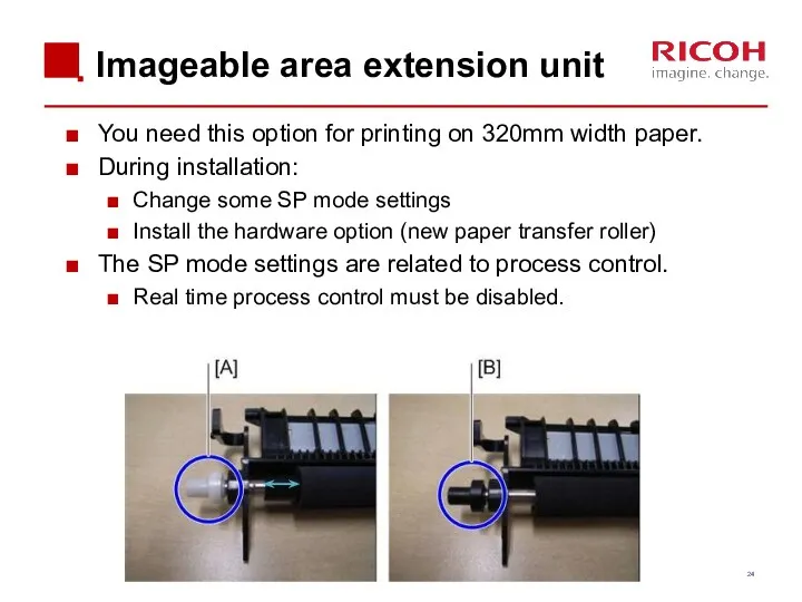
Imageable area extension unit
You need this option for printing on 320mm
Imageable area extension unit
You need this option for printing on 320mm
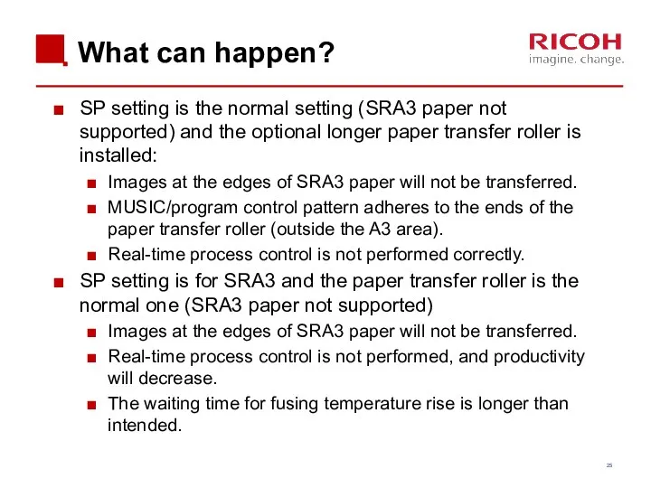
What can happen?
SP setting is the normal setting (SRA3 paper not
What can happen?
SP setting is the normal setting (SRA3 paper not
Enter SP Mode
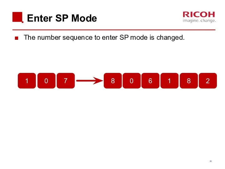
The number sequence to enter SP mode is changed.
Enter SP Mode
The number sequence to enter SP mode is changed.
![SD Card Slots [A]: SD card slot 1 (option slot)](/_ipx/f_webp&q_80&fit_contain&s_1440x1080/imagesDir/jpg/201019/slide-26.jpg)
SD Card Slots
[A]: SD card slot 1 (option slot)
[B]: SD card
SD Card Slots
[A]: SD card slot 1 (option slot)
[B]: SD card
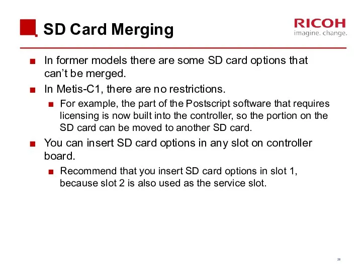
SD Card Merging
In former models there are some SD card options
SD Card Merging
In former models there are some SD card options
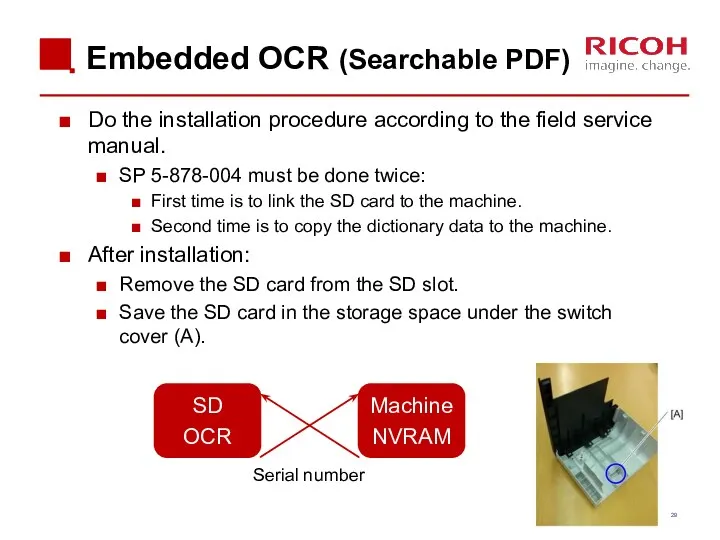
Embedded OCR (Searchable PDF)
Do the installation procedure according to the field
Embedded OCR (Searchable PDF)
Do the installation procedure according to the field
After Installing the Machine and All Options
After you have finished installing
After Installing the Machine and All Options
After you have finished installing

3. Maintenance
3. Maintenance
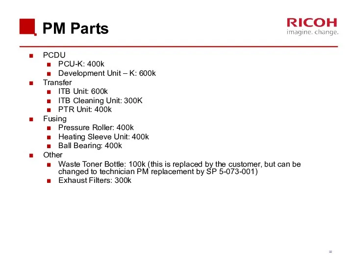
PM Parts
PCDU
PCU-K: 400k
Development Unit – K: 600k
Transfer
ITB Unit: 600k
ITB Cleaning Unit:
PM Parts
PCDU
PCU-K: 400k
Development Unit – K: 600k
Transfer
ITB Unit: 600k
ITB Cleaning Unit:
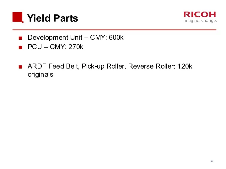
Yield Parts
Development Unit – CMY: 600k
PCU – CMY: 270k
ARDF Feed Belt,
Yield Parts
Development Unit – CMY: 600k
PCU – CMY: 270k
ARDF Feed Belt,
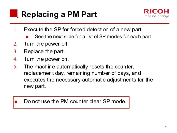
Replacing a PM Part
Execute the SP for forced detection of a
Replacing a PM Part
Execute the SP for forced detection of a
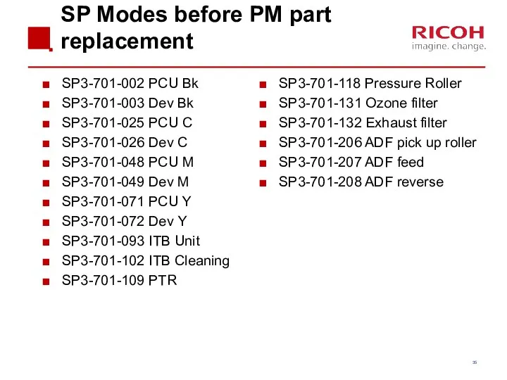
SP Modes before PM part replacement
SP3-701-002 PCU Bk
SP3-701-003 Dev Bk
SP3-701-025 PCU
SP Modes before PM part replacement
SP3-701-002 PCU Bk
SP3-701-003 Dev Bk
SP3-701-025 PCU
New Function: PM Counter
New features on the PM counter display allow
New Function: PM Counter
New features on the PM counter display allow
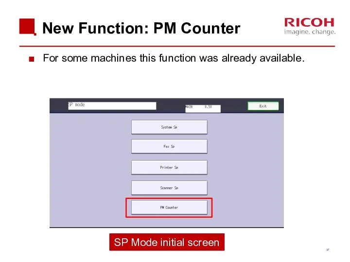
New Function: PM Counter
For some machines this function was already available.
SP
New Function: PM Counter
For some machines this function was already available.
SP
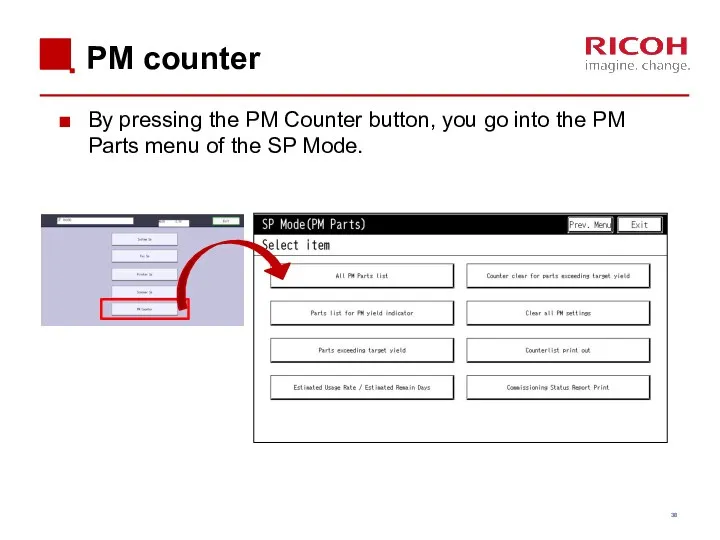
PM counter
By pressing the PM Counter button, you go into the
PM counter
By pressing the PM Counter button, you go into the
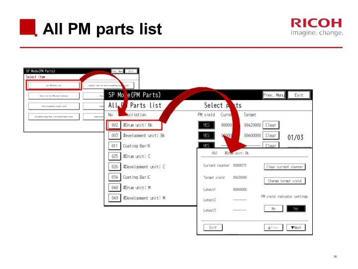
All PM parts list
All PM parts list
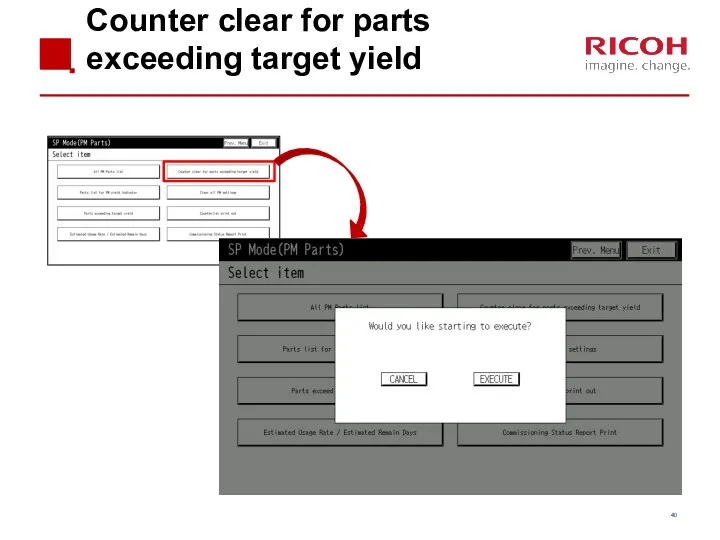
Counter clear for parts exceeding target yield
Counter clear for parts exceeding target yield
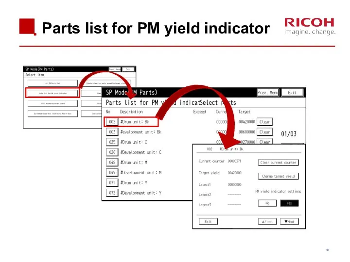
Parts list for PM yield indicator
Parts list for PM yield indicator
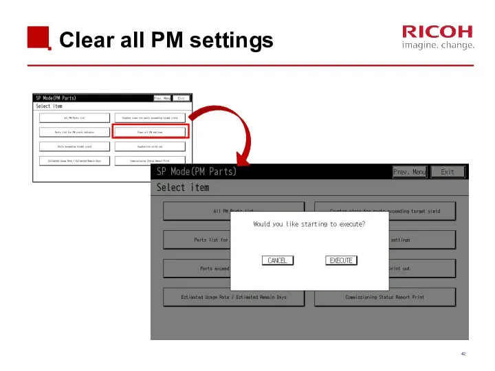
Clear all PM settings
Clear all PM settings
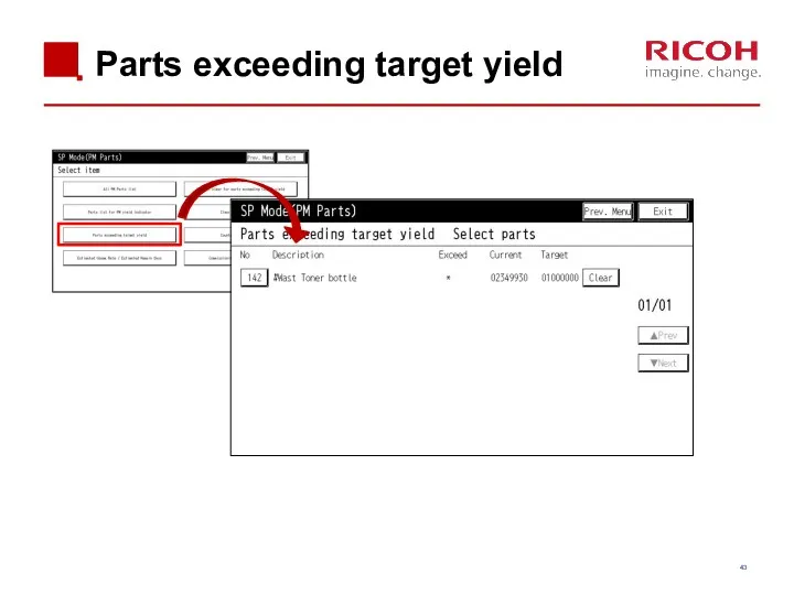
Parts exceeding target yield
Parts exceeding target yield
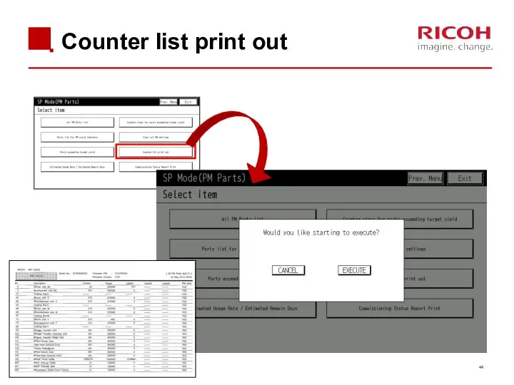
Counter list print out
Counter list print out
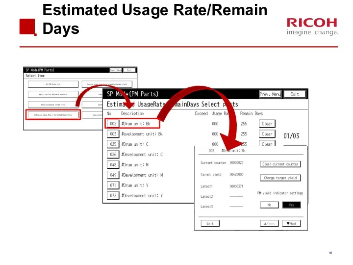
Estimated Usage Rate/Remain Days
Estimated Usage Rate/Remain Days
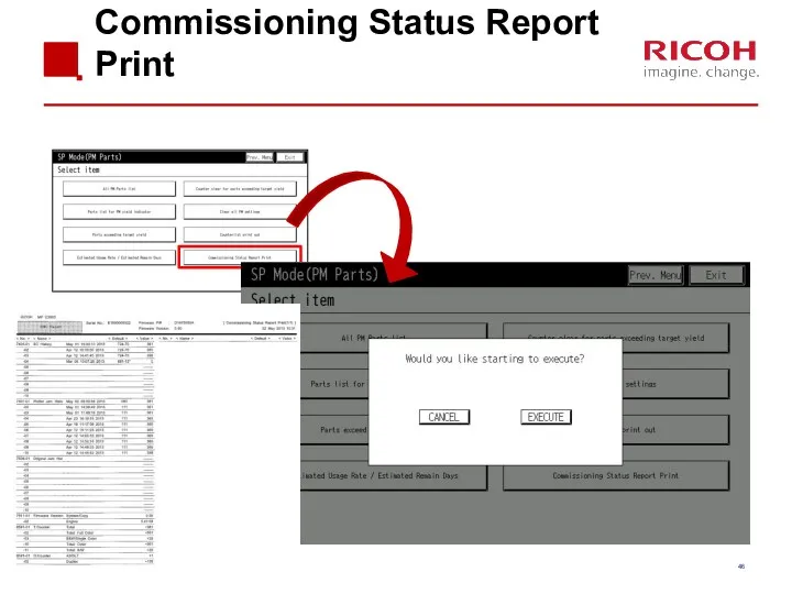
Commissioning Status Report Print
Commissioning Status Report Print
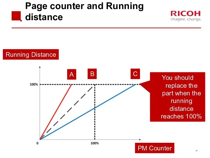
Page counter and Running distance
PM Counter
Running Distance
A
B
C
You should replace the part
Page counter and Running distance
PM Counter
Running Distance
A
B
C
You should replace the part
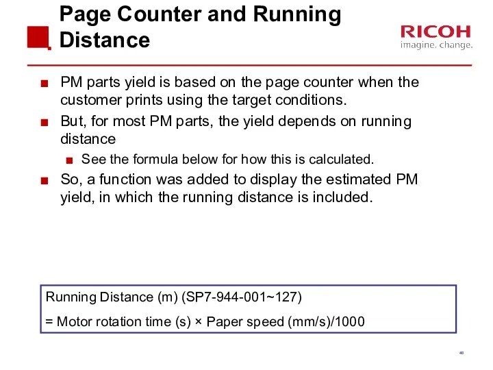
Page Counter and Running Distance
PM parts yield is based on the
Page Counter and Running Distance
PM parts yield is based on the
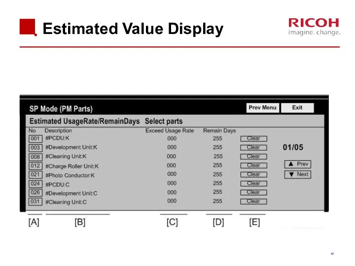
Estimated Value Display
Estimated Value Display
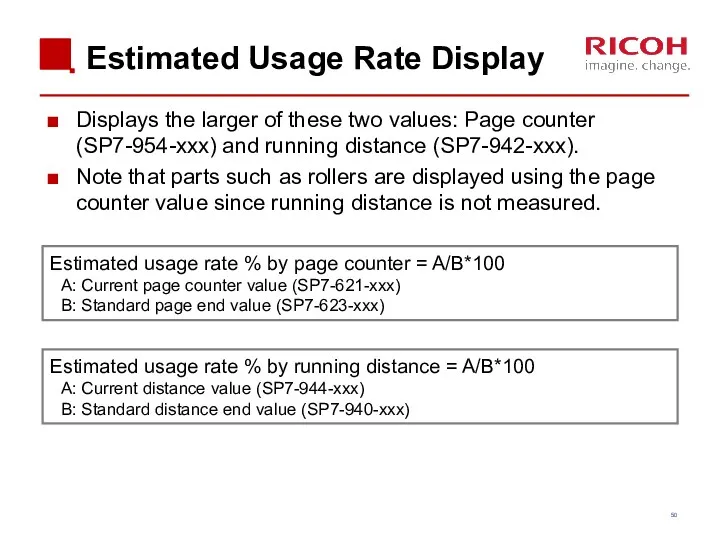
Estimated Usage Rate Display
Displays the larger of these two values: Page
Estimated Usage Rate Display
Displays the larger of these two values: Page
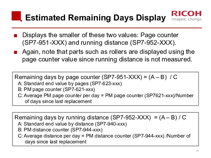
Estimated Remaining Days Display
Displays the smaller of these two values: Page
Estimated Remaining Days Display
Displays the smaller of these two values: Page
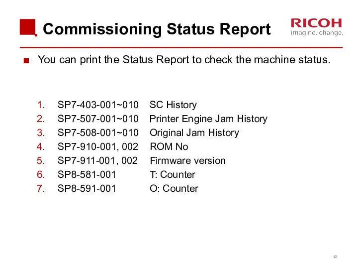
Commissioning Status Report
You can print the Status Report to check the
Commissioning Status Report
You can print the Status Report to check the

4. Detailed Section Descriptions
4. Detailed Section Descriptions
Chapter Overview
4.1 Machine Overview
4.2 Scanner
4.3 Laser Unit
4.4 PCDU
4.5 Toner Supply
4.6 Image
Chapter Overview
4.1 Machine Overview
4.2 Scanner
4.3 Laser Unit
4.4 PCDU
4.5 Toner Supply
4.6 Image
4.1 Machine Overview
4.1 Machine Overview
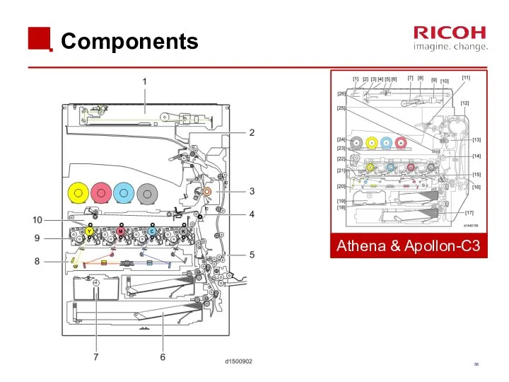
Components
Athena & Apollon-C3
Components
Athena & Apollon-C3
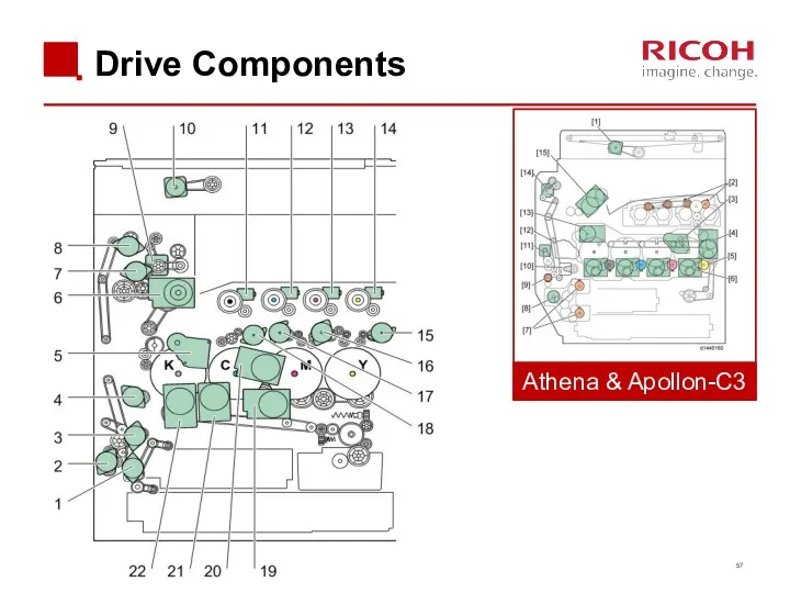
Drive Components
Athena & Apollon-C3
Drive Components
Athena & Apollon-C3
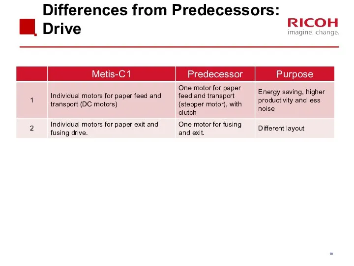
Differences from Predecessors: Drive
Differences from Predecessors: Drive
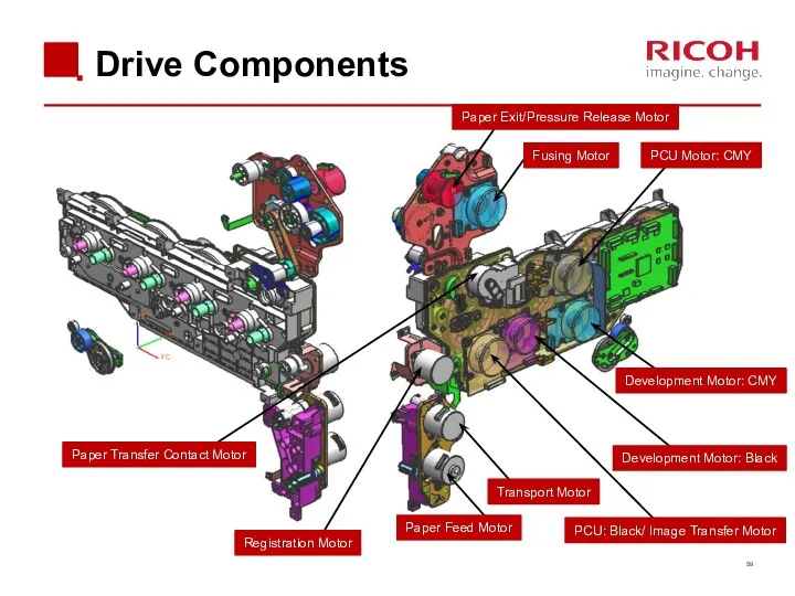
Drive Components
Paper Feed Motor
Transport Motor
Registration Motor
Paper Transfer Contact Motor
Fusing Motor
Development Motor:
Drive Components
Paper Feed Motor
Transport Motor
Registration Motor
Paper Transfer Contact Motor
Fusing Motor
Development Motor:
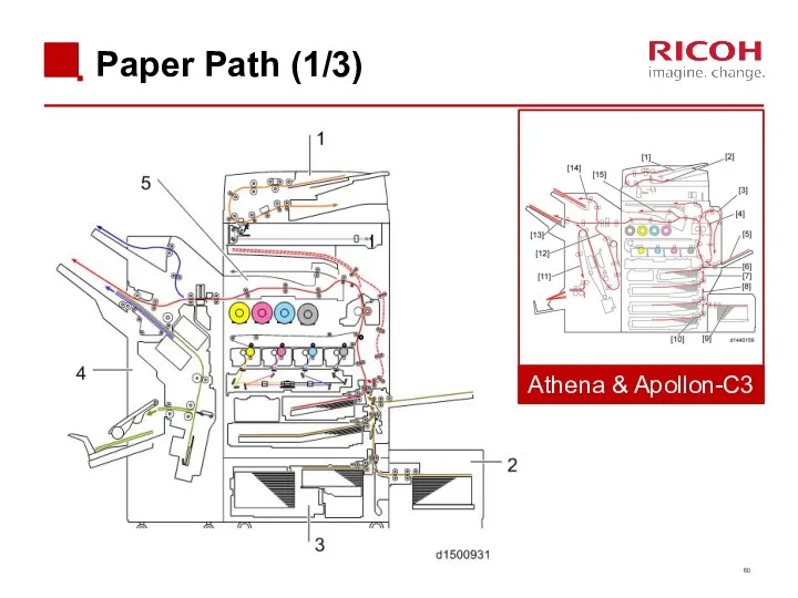
Paper Path (1/3)
Athena & Apollon-C3
Paper Path (1/3)
Athena & Apollon-C3
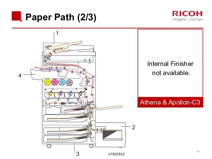
Paper Path (2/3)
Athena & Apollon-C3
Internal Finisher
not available.
Paper Path (2/3)
Athena & Apollon-C3
Internal Finisher
not available.
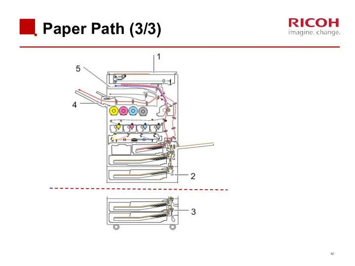
Paper Path (3/3)
Paper Path (3/3)
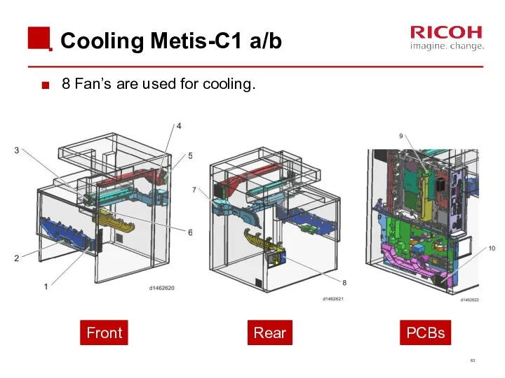
Cooling Metis-C1 a/b
8 Fan’s are used for cooling.
Front
Rear
PCBs
Cooling Metis-C1 a/b
8 Fan’s are used for cooling.
Front
Rear
PCBs
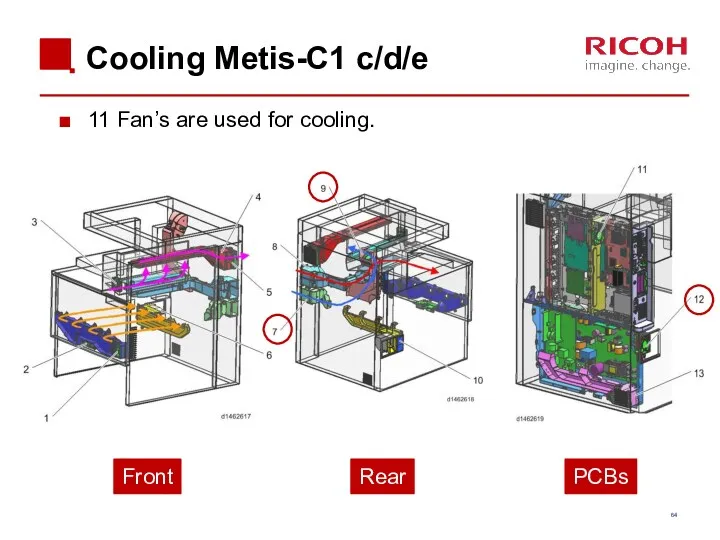
Cooling Metis-C1 c/d/e
11 Fan’s are used for cooling.
Front
Rear
PCBs
Cooling Metis-C1 c/d/e
11 Fan’s are used for cooling.
Front
Rear
PCBs
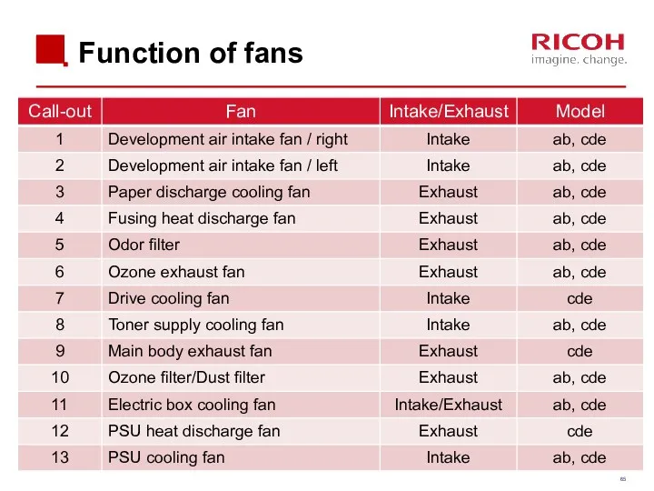
Function of fans
Function of fans
Cooling Notes
Toner supply cooling duct: The shape of the duct for
Cooling Notes
Toner supply cooling duct: The shape of the duct for
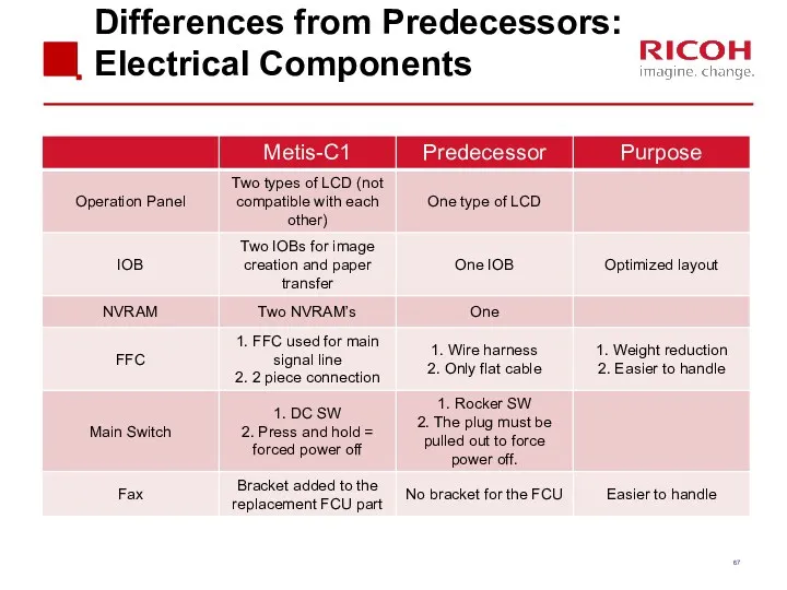
Differences from Predecessors:
Electrical Components
Differences from Predecessors:
Electrical Components
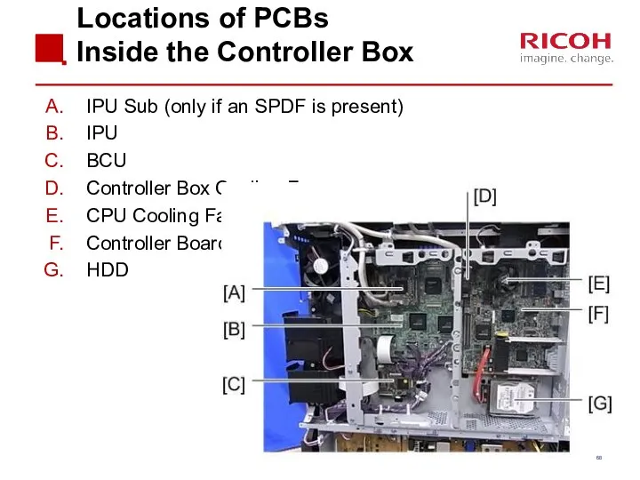
Locations of PCBs
Inside the Controller Box
IPU Sub (only if an SPDF
Locations of PCBs
Inside the Controller Box
IPU Sub (only if an SPDF
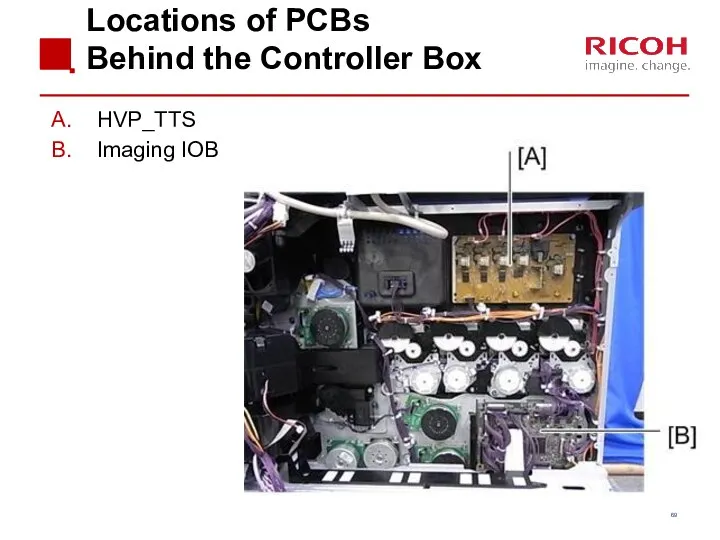
Locations of PCBs
Behind the Controller Box
HVP_TTS
Imaging IOB
Locations of PCBs
Behind the Controller Box
HVP_TTS
Imaging IOB
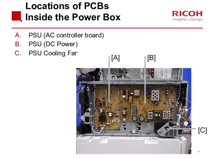
Locations of PCBs
Inside the Power Box
PSU (AC controller board)
PSU (DC Power)
PSU
Locations of PCBs
Inside the Power Box
PSU (AC controller board)
PSU (DC Power)
PSU
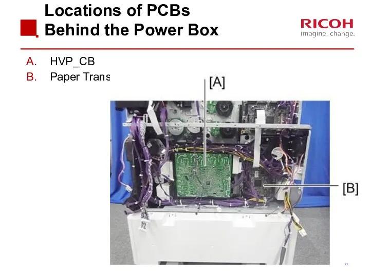
Locations of PCBs
Behind the Power Box
HVP_CB
Paper Transport IOB
Locations of PCBs
Behind the Power Box
HVP_CB
Paper Transport IOB
Differences from Predecessors:
Servicing
Differences from Predecessors:
Servicing
![Switch off procedure Push the power switch [A] on the](/_ipx/f_webp&q_80&fit_contain&s_1440x1080/imagesDir/jpg/201019/slide-72.jpg)
Switch off procedure
Push the power switch [A] on the machine.
Wait until
Switch off procedure
Push the power switch [A] on the machine.
Wait until
Starting the machine again
To start the machine, press the main power
Starting the machine again
To start the machine, press the main power
Forced Shutdown
In case normal shutdown does not complete, the machine
Forced Shutdown
In case normal shutdown does not complete, the machine
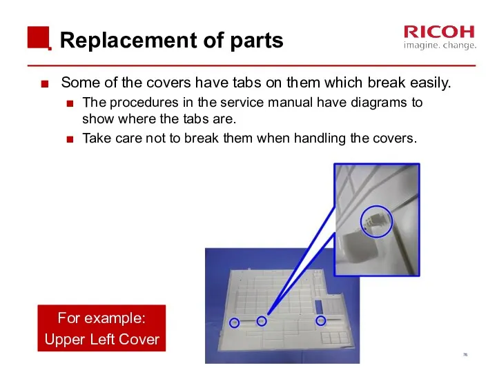
Replacement of parts
Some of the covers have tabs on them which
Replacement of parts
Some of the covers have tabs on them which
LCD Panel (1/2)
LCD panels from two different vendors are used.
Depending
LCD Panel (1/2)
LCD panels from two different vendors are used.
Depending
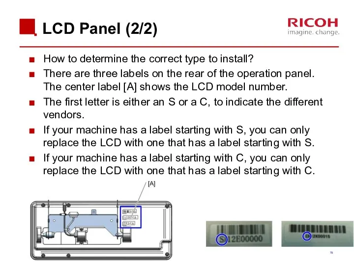
LCD Panel (2/2)
How to determine the correct type to install?
There are
LCD Panel (2/2)
How to determine the correct type to install?
There are
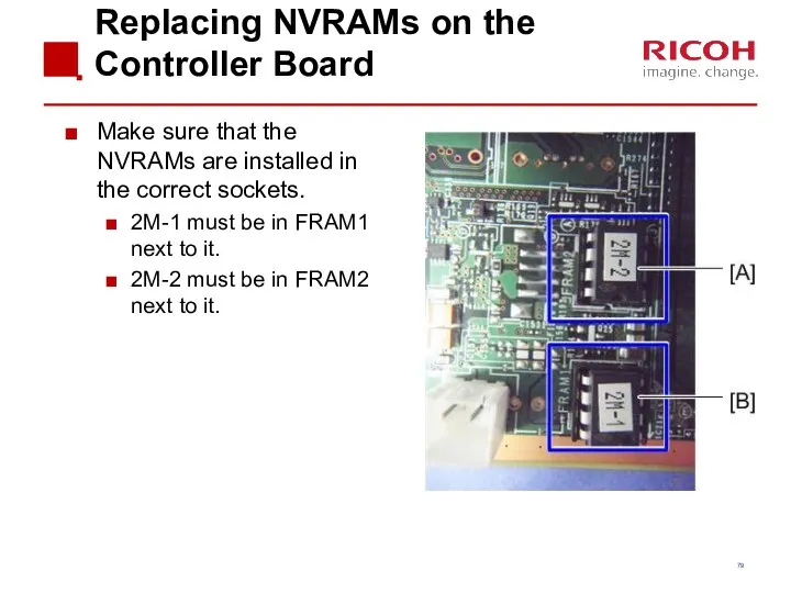
Replacing NVRAMs on the Controller Board
Make sure that the NVRAMs are
Replacing NVRAMs on the Controller Board
Make sure that the NVRAMs are
4.2 Scanner
4.2 Scanner
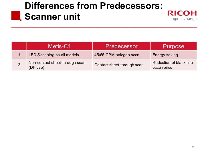
Differences from Predecessors: Scanner unit
Differences from Predecessors: Scanner unit
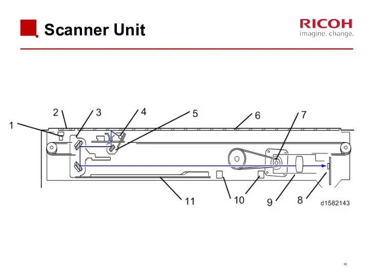
Scanner Unit
Scanner Unit
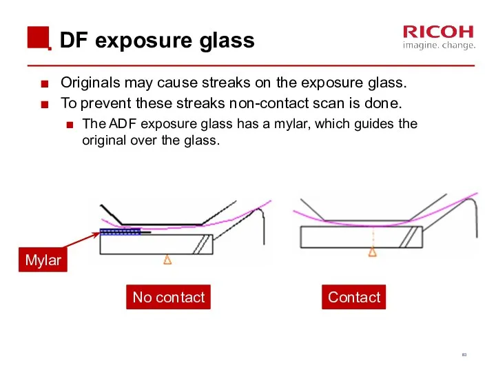
DF exposure glass
Originals may cause streaks on the exposure glass.
To prevent
DF exposure glass
Originals may cause streaks on the exposure glass.
To prevent
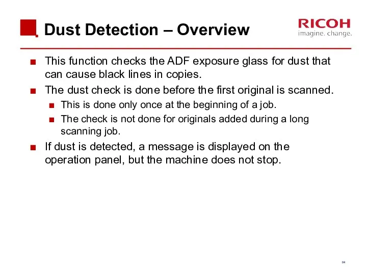
Dust Detection – Overview
This function checks the ADF exposure glass for
Dust Detection – Overview
This function checks the ADF exposure glass for
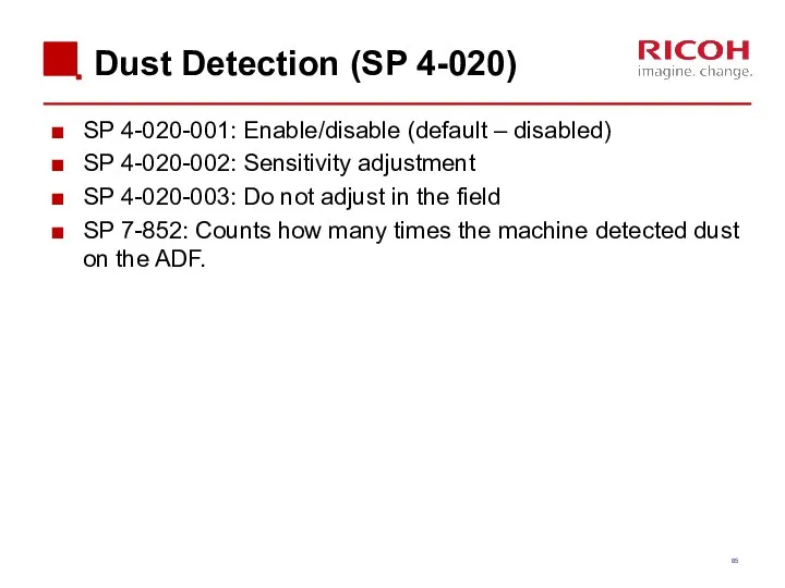
Dust Detection (SP 4-020)
SP 4-020-001: Enable/disable (default – disabled)
SP 4-020-002: Sensitivity
Dust Detection (SP 4-020)
SP 4-020-001: Enable/disable (default – disabled)
SP 4-020-002: Sensitivity
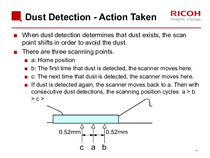
Dust Detection - Action Taken
When dust detection determines that dust exists,
Dust Detection - Action Taken
When dust detection determines that dust exists,
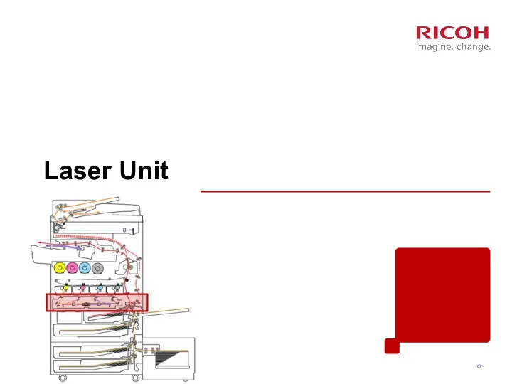
Laser Unit
Laser Unit
Differences from Predecessors: Laser unit
Differences from Predecessors: Laser unit
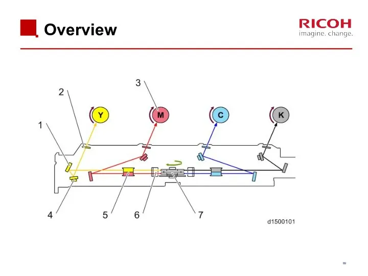
Overview
Overview
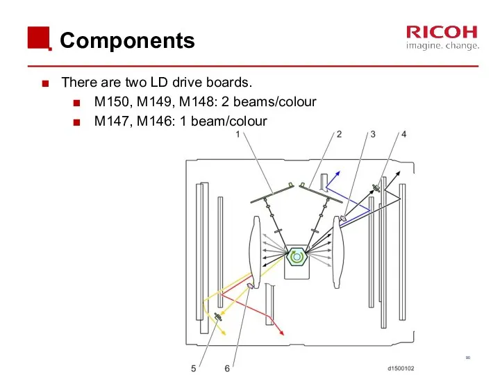
Components
There are two LD drive boards.
M150, M149, M148: 2 beams/colour
M147, M146:
Components
There are two LD drive boards.
M150, M149, M148: 2 beams/colour
M147, M146:
Skew Adjustment
The 2nd mirrors for C, M, and Y have a
Skew Adjustment
The 2nd mirrors for C, M, and Y have a
Replacing the Laser Unit
After installing the new unit:
Disconnect the skew correction
Replacing the Laser Unit
After installing the new unit:
Disconnect the skew correction
PCDU
PCDU
Differences from Predecessors: PCDU
Differences from Predecessors: PCDU
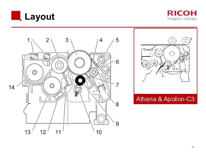
Layout
Athena & Apollon-C3
Layout
Athena & Apollon-C3
Differences from Predecessors: PCU
Differences from Predecessors: PCU
Differences from Predecessors: Development
Differences from Predecessors: Development
Development
A two-component development system is used.
One motor drives the K development,
Development
A two-component development system is used.
One motor drives the K development,
Development Unit Components
Development Unit Components
Replacing Note for PCDU or PCU
Before replacing a PCU or PCDU,
Replacing Note for PCDU or PCU
Before replacing a PCU or PCDU,
Replacement (1/3)
Take care not to damage the part of the rear
Replacement (1/3)
Take care not to damage the part of the rear
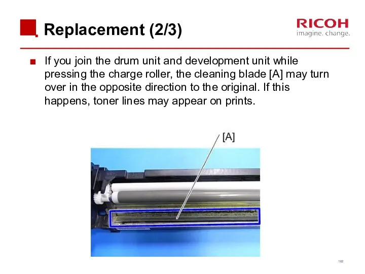
Replacement (2/3)
If you join the drum unit and development unit while
Replacement (2/3)
If you join the drum unit and development unit while
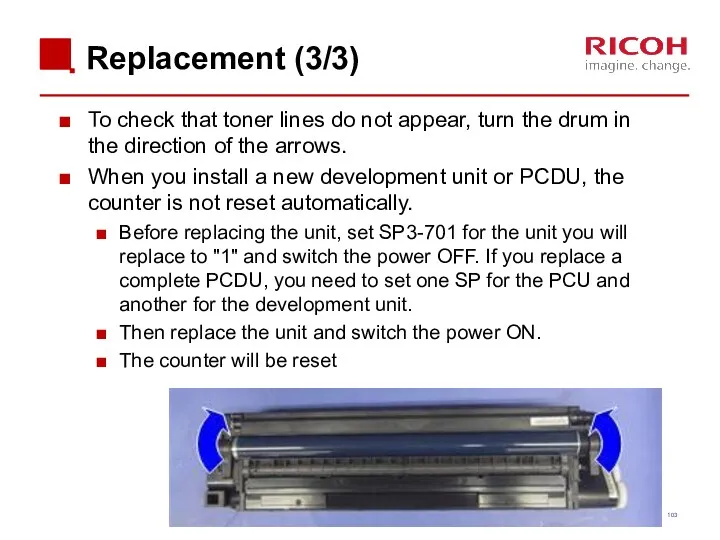
Replacement (3/3)
To check that toner lines do not appear, turn the
Replacement (3/3)
To check that toner lines do not appear, turn the
Replacing the PCDU / PCU on a D149 or D150
An additional
Replacing the PCDU / PCU on a D149 or D150
An additional
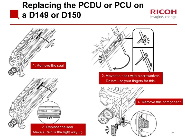
Replacing the PCDU or PCU on a D149 or D150
1. Remove
Replacing the PCDU or PCU on a D149 or D150
1. Remove
Toner Supply
Toner Supply
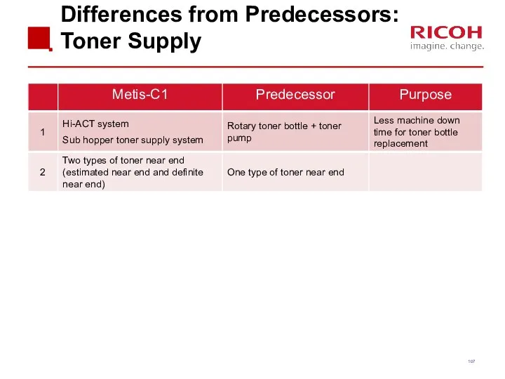
Differences from Predecessors: Toner Supply
Differences from Predecessors: Toner Supply
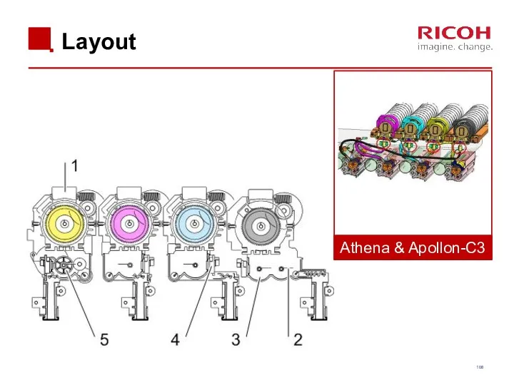
Layout
Athena & Apollon-C3
Layout
Athena & Apollon-C3
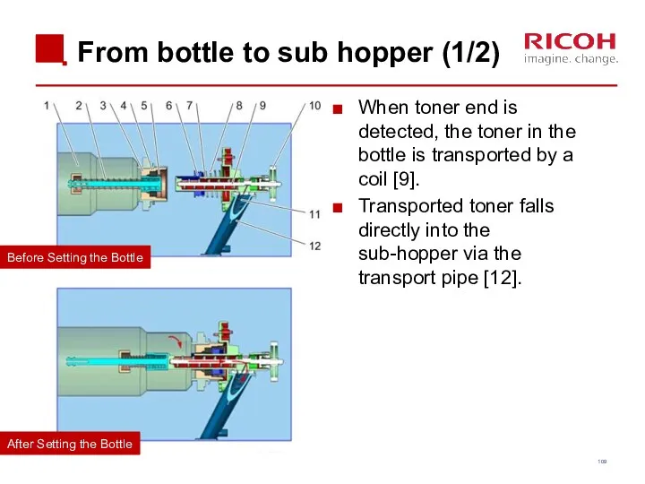
From bottle to sub hopper (1/2)
When toner end is detected, the
From bottle to sub hopper (1/2)
When toner end is detected, the
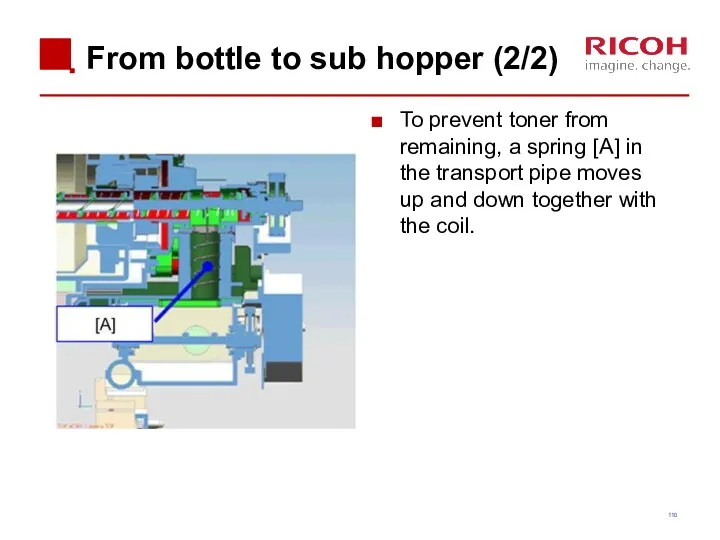
From bottle to sub hopper (2/2)
To prevent toner from remaining, a
From bottle to sub hopper (2/2)
To prevent toner from remaining, a
Toner Near-end Detection
The machine estimates the amount of toner remaining in
Toner Near-end Detection
The machine estimates the amount of toner remaining in
‘Estimated Toner Near-end’
If the amount of remaining toner falls below a
‘Estimated Toner Near-end’
If the amount of remaining toner falls below a
‘Definite Toner Near-end’
If the amount of remaining toner falls below
‘Definite Toner Near-end’
If the amount of remaining toner falls below
Definite Toner Near-end detection
The machine checks the toner end sensor every
Definite Toner Near-end detection
The machine checks the toner end sensor every
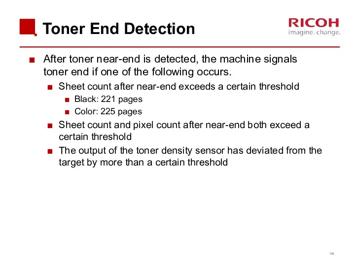
Toner End Detection
After toner near-end is detected, the machine signals toner
Toner End Detection
After toner near-end is detected, the machine signals toner
Paper Feed
Paper Feed
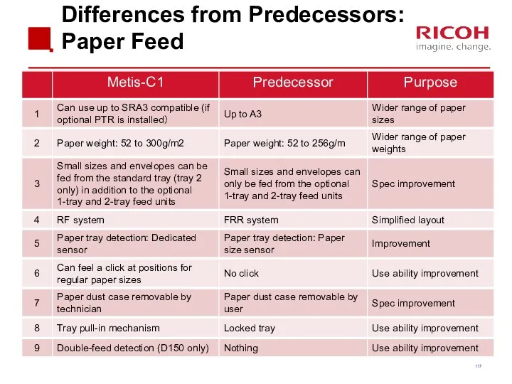
Differences from Predecessors: Paper Feed
Differences from Predecessors: Paper Feed
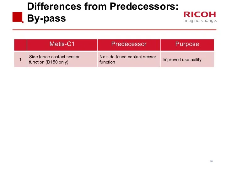
Differences from Predecessors: By-pass
Differences from Predecessors: By-pass
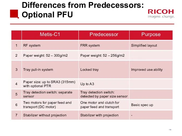
Differences from Predecessors: Optional PFU
Differences from Predecessors: Optional PFU
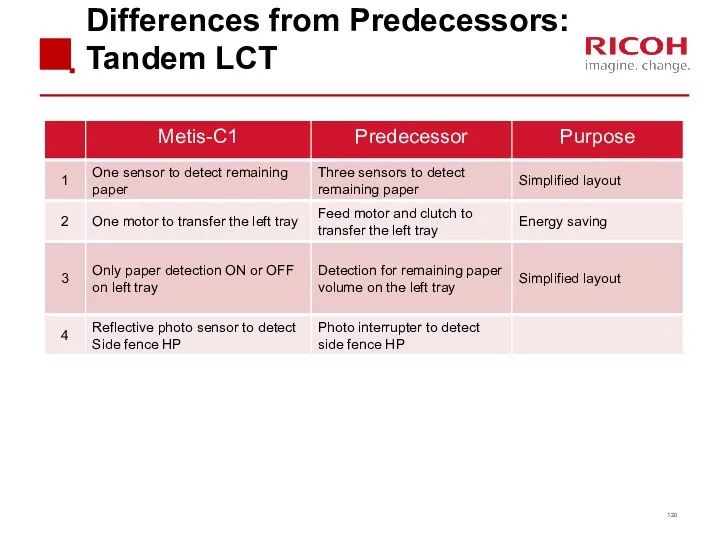
Differences from Predecessors: Tandem LCT
Differences from Predecessors: Tandem LCT
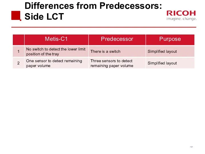
Differences from Predecessors: Side LCT
Differences from Predecessors: Side LCT
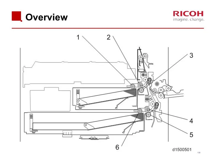
Overview
Overview
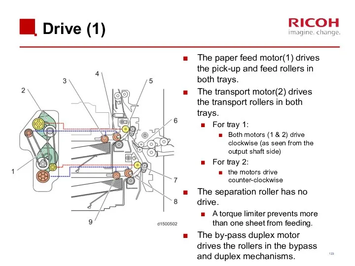
Drive (1)
The paper feed motor(1) drives the pick-up and feed rollers
Drive (1)
The paper feed motor(1) drives the pick-up and feed rollers
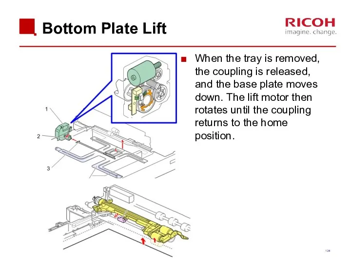
Bottom Plate Lift
When the tray is removed, the coupling is released,
Bottom Plate Lift
When the tray is removed, the coupling is released,
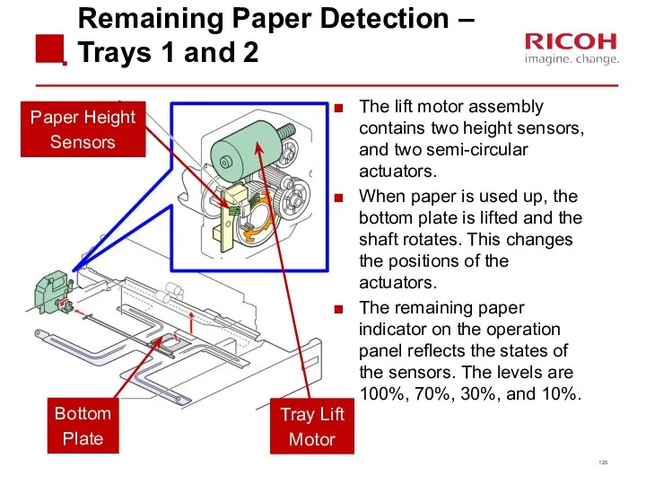
Remaining Paper Detection – Trays 1 and 2
The lift motor assembly
Remaining Paper Detection – Trays 1 and 2
The lift motor assembly
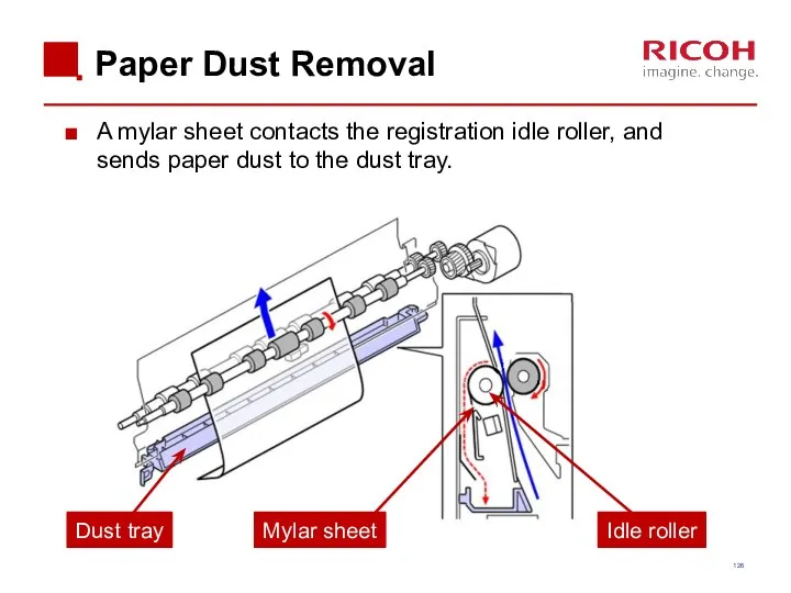
Paper Dust Removal
A mylar sheet contacts the registration idle roller, and
Paper Dust Removal
A mylar sheet contacts the registration idle roller, and
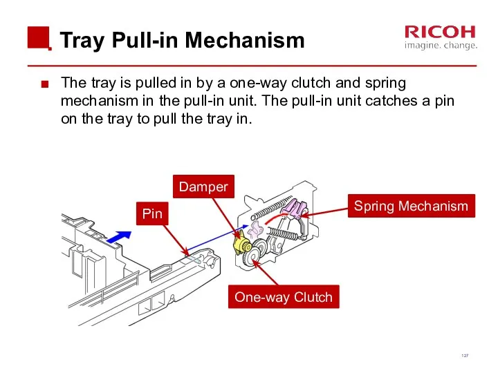
Tray Pull-in Mechanism
The tray is pulled in by a one-way clutch
Tray Pull-in Mechanism
The tray is pulled in by a one-way clutch
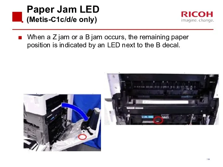
Paper Jam LED
(Metis-C1c/d/e only)
When a Z jam or a B
Paper Jam LED
(Metis-C1c/d/e only)
When a Z jam or a B
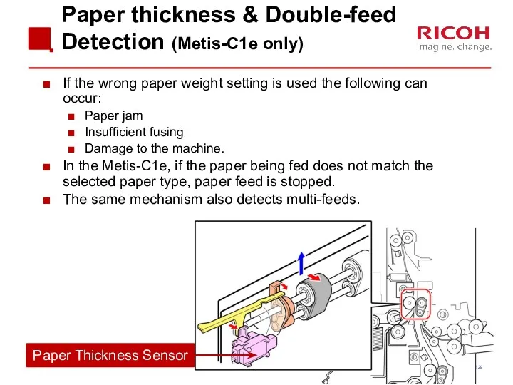
Paper thickness & Double-feed Detection (Metis-C1e only)
If the wrong paper weight
Paper thickness & Double-feed Detection (Metis-C1e only)
If the wrong paper weight
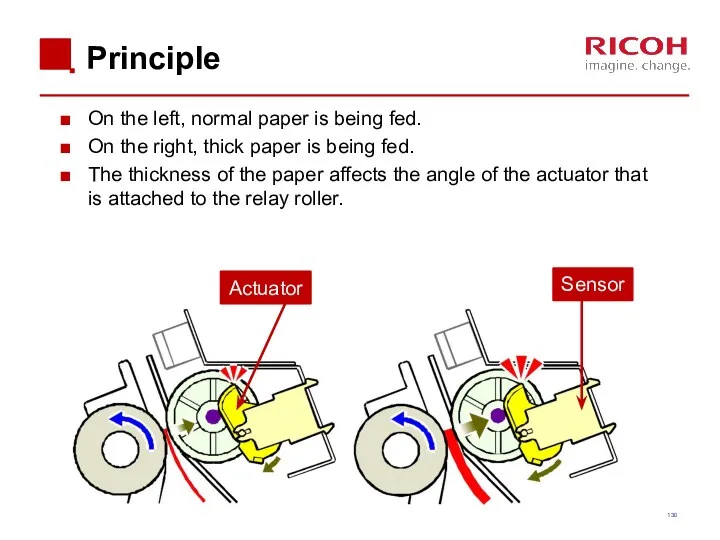
Principle
On the left, normal paper is being fed.
On the right, thick
Principle
On the left, normal paper is being fed.
On the right, thick
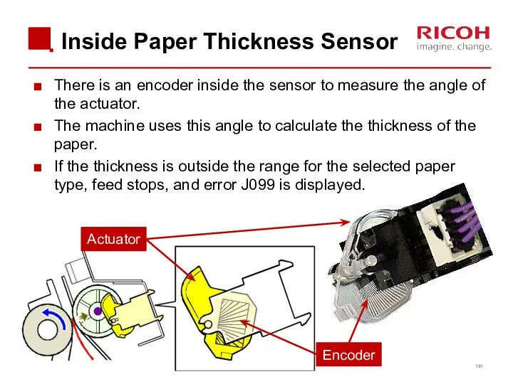
Inside Paper Thickness Sensor
There is an encoder inside the sensor to
Inside Paper Thickness Sensor
There is an encoder inside the sensor to
Double-feed Detection
The machine compares the thickness of the current sheet with
Double-feed Detection
The machine compares the thickness of the current sheet with
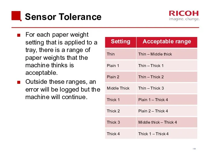
Sensor Tolerance
For each paper weight setting that is applied to a
Sensor Tolerance
For each paper weight setting that is applied to a
Paper Thickness Detection
Other Points
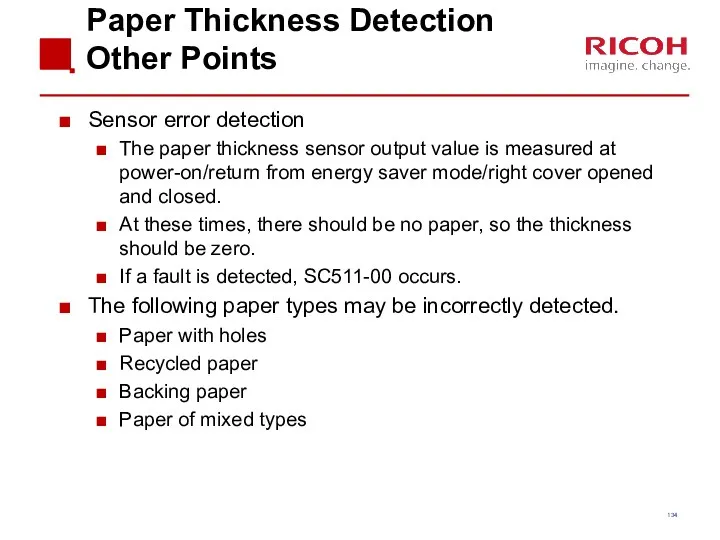
Sensor error detection
The paper thickness sensor output value
Paper Thickness Detection
Other Points
Sensor error detection
The paper thickness sensor output value
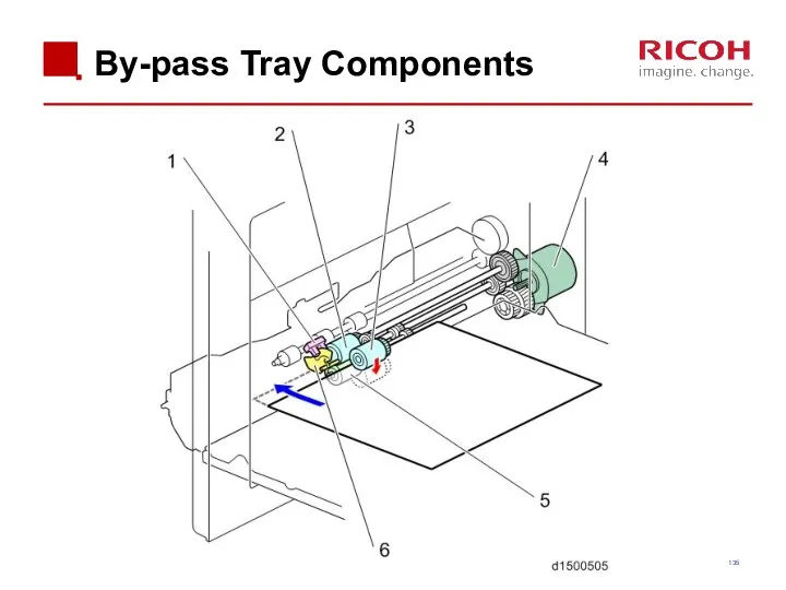
By-pass Tray Components
By-pass Tray Components
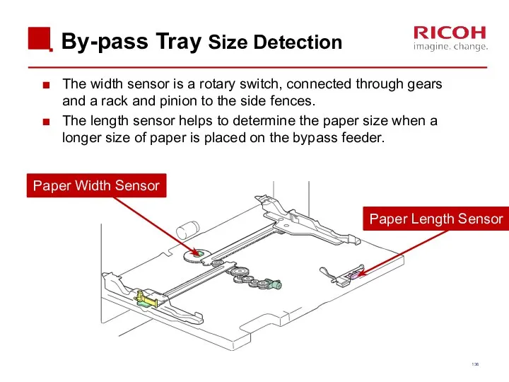
By-pass Tray Size Detection
The width sensor is a rotary switch, connected
By-pass Tray Size Detection
The width sensor is a rotary switch, connected
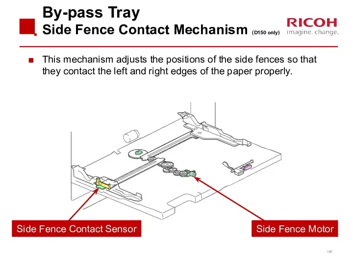
By-pass Tray
Side Fence Contact Mechanism (D150 only)
This mechanism adjusts the positions
By-pass Tray
Side Fence Contact Mechanism (D150 only)
This mechanism adjusts the positions
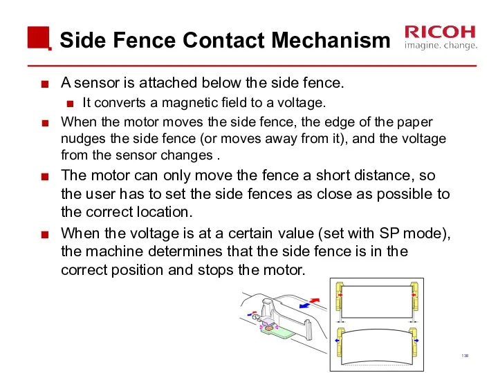
Side Fence Contact Mechanism
A sensor is attached below the side fence.
Side Fence Contact Mechanism
A sensor is attached below the side fence.
Exercise
Remove the 1st and 2nd paper feed unit and remove on
Exercise
Remove the 1st and 2nd paper feed unit and remove on

Image Transfer
Image Transfer
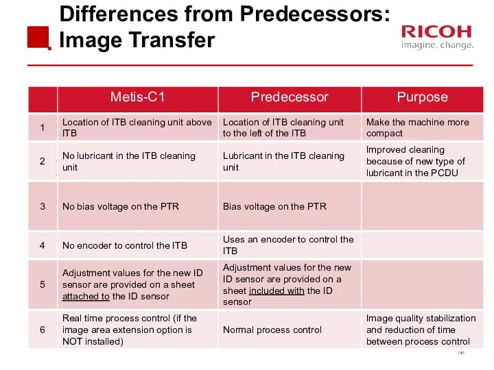
Differences from Predecessors: Image Transfer
Differences from Predecessors: Image Transfer
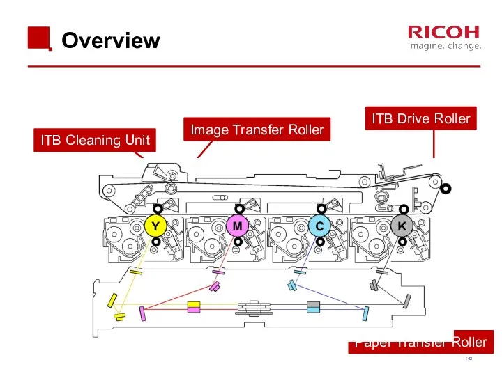
Overview
Image Transfer Roller
ITB Drive Roller
Paper Transfer Roller
ITB Cleaning Unit
Overview
Image Transfer Roller
ITB Drive Roller
Paper Transfer Roller
ITB Cleaning Unit
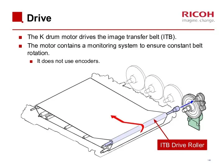
Drive
The K drum motor drives the image transfer belt (ITB).
The motor
Drive
The K drum motor drives the image transfer belt (ITB).
The motor
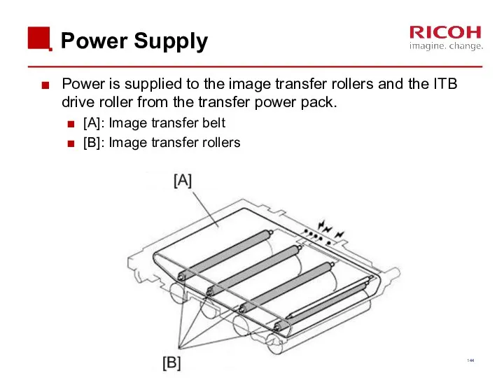
Power Supply
Power is supplied to the image transfer rollers and the
Power Supply
Power is supplied to the image transfer rollers and the
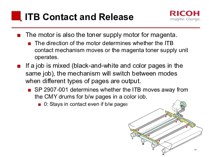
ITB Contact and Release
The motor is also the toner supply motor
ITB Contact and Release
The motor is also the toner supply motor
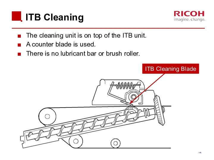
ITB Cleaning
The cleaning unit is on top of the ITB unit.
A
ITB Cleaning
The cleaning unit is on top of the ITB unit.
A
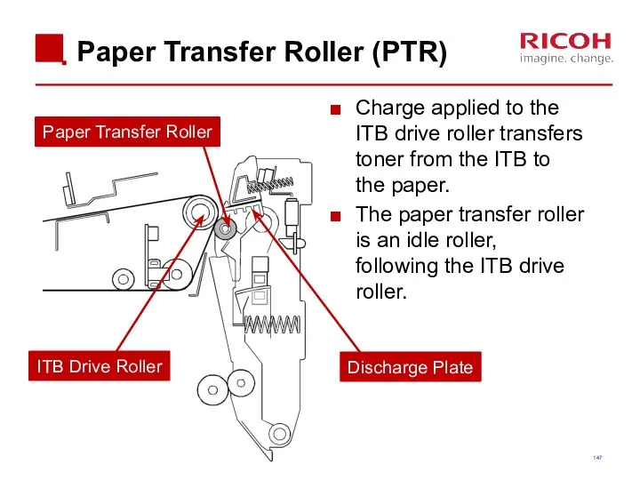
Paper Transfer Roller (PTR)
Charge applied to the ITB drive roller transfers
Paper Transfer Roller (PTR)
Charge applied to the ITB drive roller transfers
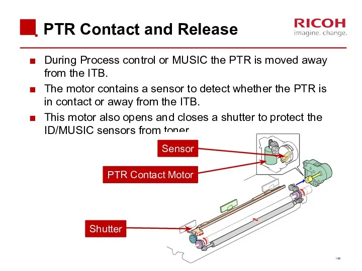
PTR Contact and Release
During Process control or MUSIC the PTR is
PTR Contact and Release
During Process control or MUSIC the PTR is
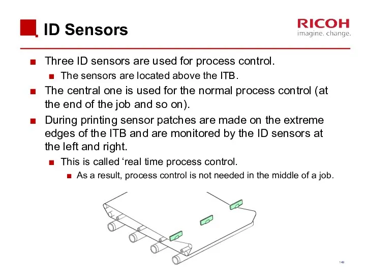
ID Sensors
Three ID sensors are used for process control.
The sensors are
ID Sensors
Three ID sensors are used for process control.
The sensors are
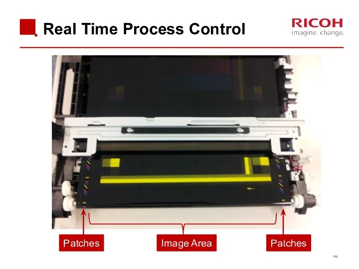
Real Time Process Control
Image Area
Patches
Patches
Real Time Process Control
Image Area
Patches
Patches
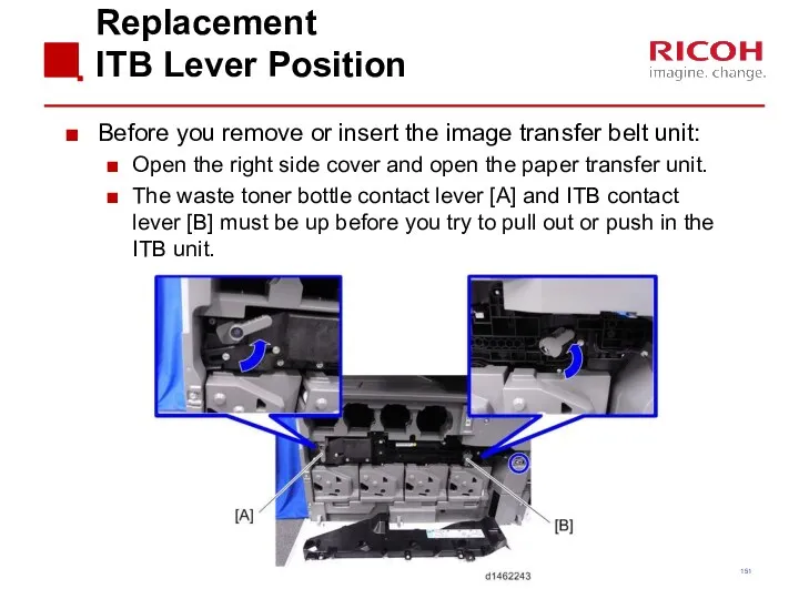
Replacement
ITB Lever Position
Before you remove or insert the image transfer belt
Replacement
ITB Lever Position
Before you remove or insert the image transfer belt
Replacement ITB Cleaning Unit
When removing the ITB cleaning unit:
Turn the ITB
Replacement ITB Cleaning Unit
When removing the ITB cleaning unit:
Turn the ITB
Replacement ID Sensors
Before you replace the ID sensor, you must input
Replacement ID Sensors
Before you replace the ID sensor, you must input
Fusing
Fusing
Differences from Predecessors: Fusing
Differences from Predecessors: Fusing
Components
Athena & Apollon-C3
Components
Athena & Apollon-C3
QSU-DH Fusing Method
The fusing system is the same as the Athena-C3
QSU-DH Fusing Method
The fusing system is the same as the Athena-C3
Shield
To prevent the temperature at the edges of the heating sleeve
Shield
To prevent the temperature at the edges of the heating sleeve
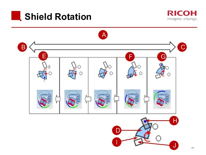
Shield Rotation
A
B
C
D
E
F
J
I
H
G
Shield Rotation
A
B
C
D
E
F
J
I
H
G
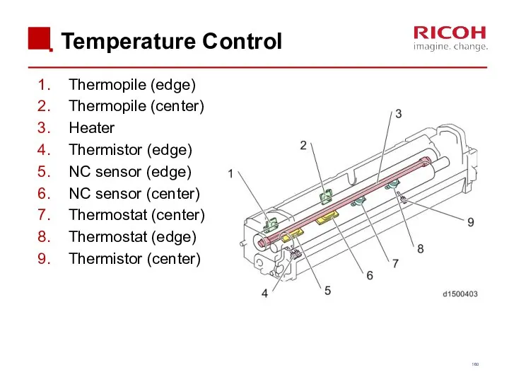
Temperature Control
Thermopile (edge)
Thermopile (center)
Heater
Thermistor (edge)
NC sensor (edge)
NC sensor (center)
Thermostat (center)
Thermostat (edge)
Thermistor
Temperature Control
Thermopile (edge)
Thermopile (center)
Heater
Thermistor (edge)
NC sensor (edge)
NC sensor (center)
Thermostat (center)
Thermostat (edge)
Thermistor
CPM Down Control
Handling Low Temperatures
The central thermopile is checked at regular
CPM Down Control
Handling Low Temperatures
The central thermopile is checked at regular
CPM Down Control
Handling High Temperatures
Because the fusing unit has a low
CPM Down Control
Handling High Temperatures
Because the fusing unit has a low
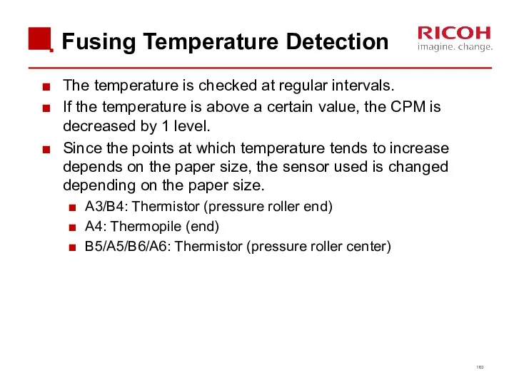
Fusing Temperature Detection
The temperature is checked at regular intervals.
If the temperature
Fusing Temperature Detection
The temperature is checked at regular intervals.
If the temperature
Paper Passage Time
Depending on the paper size, it may not be
Paper Passage Time
Depending on the paper size, it may not be
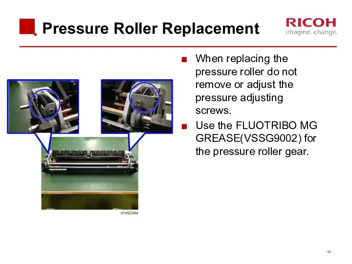
Pressure Roller Replacement
When replacing the pressure roller do not remove
Pressure Roller Replacement
When replacing the pressure roller do not remove
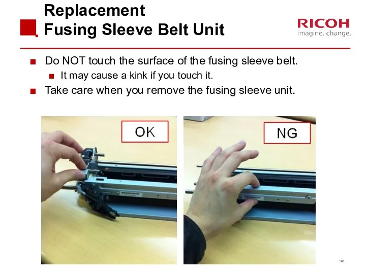
Replacement
Fusing Sleeve Belt Unit
Do NOT touch the surface of the fusing
Replacement
Fusing Sleeve Belt Unit
Do NOT touch the surface of the fusing
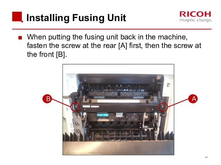
Installing Fusing Unit
When putting the fusing unit back in the machine,
Installing Fusing Unit
When putting the fusing unit back in the machine,
Fusing Shield Motor Test
Remove the fusing unit.
The motor rotation is not
Fusing Shield Motor Test
Remove the fusing unit.
The motor rotation is not
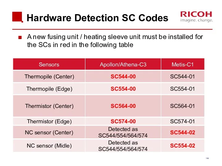
Hardware Detection SC Codes
A new fusing unit / heating sleeve unit
Hardware Detection SC Codes
A new fusing unit / heating sleeve unit
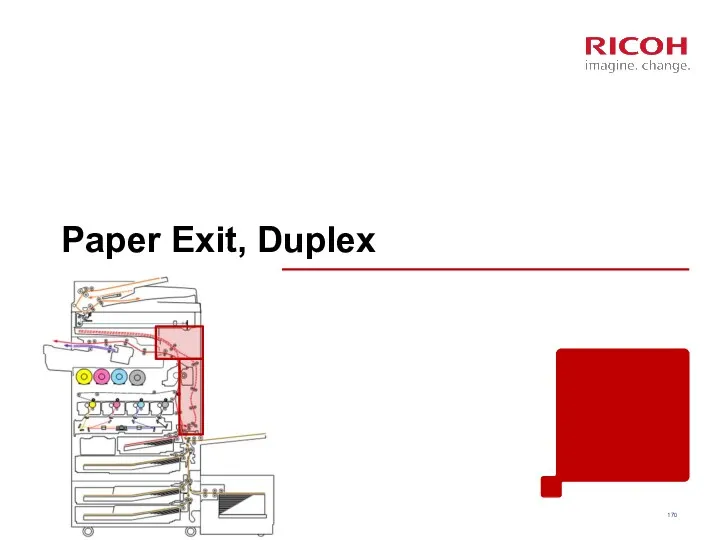
Paper Exit, Duplex
Paper Exit, Duplex
Differences from Predecessors: Duplex
Differences from Predecessors: Duplex
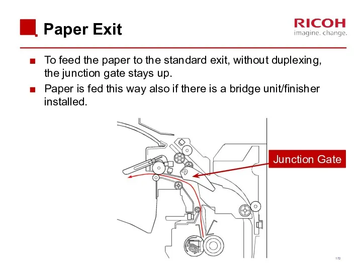
Paper Exit
To feed the paper to the standard exit, without duplexing,
Paper Exit
To feed the paper to the standard exit, without duplexing,
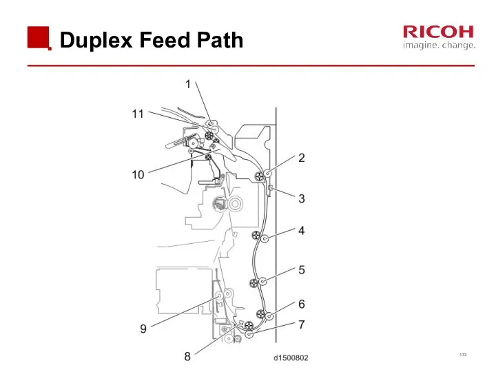
Duplex Feed Path
Duplex Feed Path
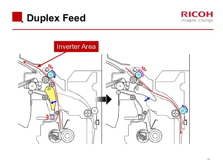
Duplex Feed
Inverter Area
Duplex Feed
Inverter Area
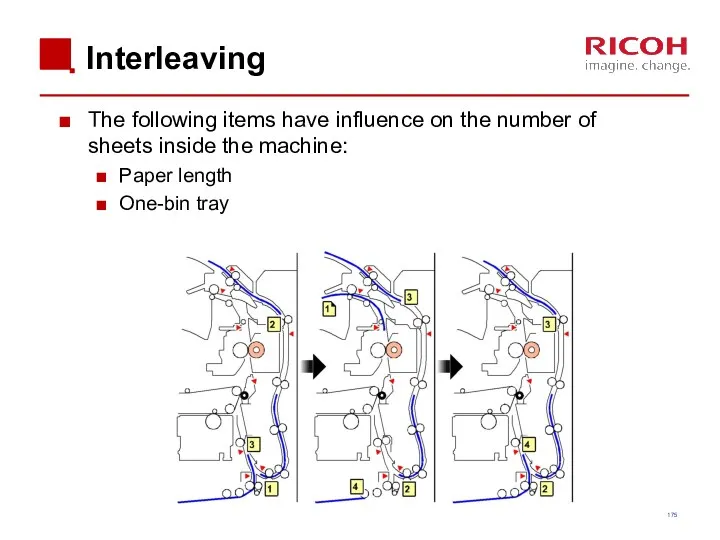
Interleaving
The following items have influence on the number of sheets inside
Interleaving
The following items have influence on the number of sheets inside
Waste Toner Collection
Waste Toner Collection
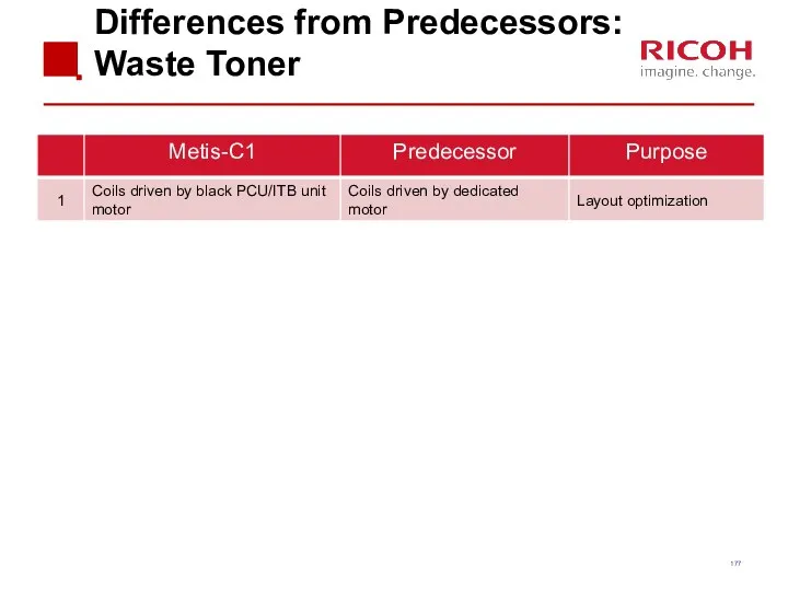
Differences from Predecessors: Waste Toner
Differences from Predecessors: Waste Toner
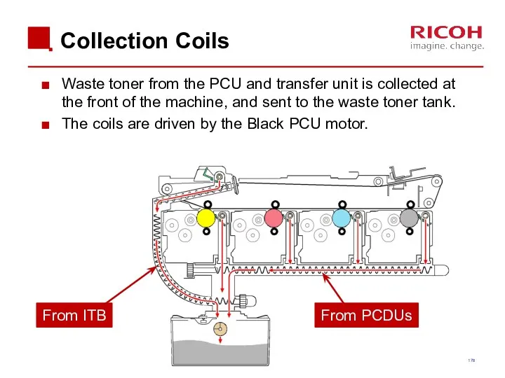
Collection Coils
Waste toner from the PCU and transfer unit is collected
Collection Coils
Waste toner from the PCU and transfer unit is collected
Sensors
Bottle set switch: If this does not detect the bottle, the
Sensors
Bottle set switch: If this does not detect the bottle, the

5. Troubleshooting
5. Troubleshooting
Capturing the Debug Logs (1/3)
Debug logs for the controller, engine, and
Capturing the Debug Logs (1/3)
Debug logs for the controller, engine, and
Capturing the Debug Logs (2/3)
Insert the SD card into the slot
Capturing the Debug Logs (2/3)
Insert the SD card into the slot
Capturing the Debug Logs (3/3)
The debug logs are saved with the
Capturing the Debug Logs (3/3)
The debug logs are saved with the
6. Android Operation Panel
Smart Operation Panel Type M3
(D148)
6. Android Operation Panel
Smart Operation Panel Type M3
(D148)
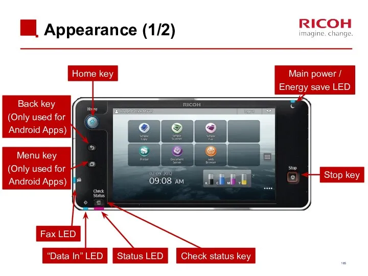
Appearance (1/2)
Home key
Back key
(Only used for
Android Apps)
Check status key
Stop key
Main
Appearance (1/2)
Home key
Back key
(Only used for
Android Apps)
Check status key
Stop key
Main
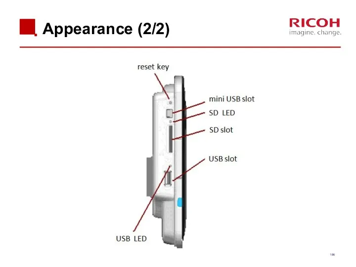
Appearance (2/2)
Appearance (2/2)
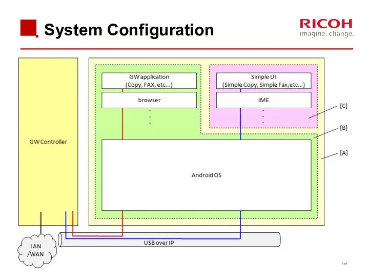
System Configuration
System Configuration
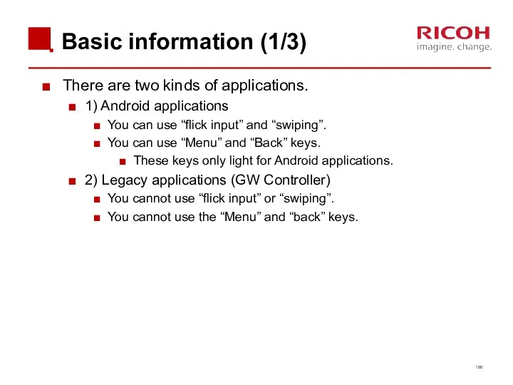
Basic information (1/3)
There are two kinds of applications.
1) Android applications
You can
Basic information (1/3)
There are two kinds of applications.
1) Android applications
You can
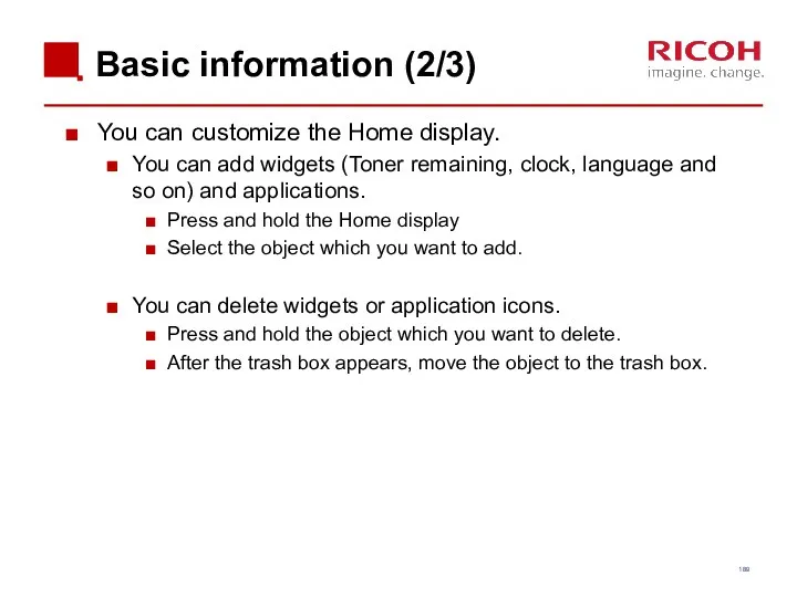
Basic information (2/3)
You can customize the Home display.
You can add widgets
Basic information (2/3)
You can customize the Home display.
You can add widgets
Basic information (3/3)
SC or machine status is displayed in legacy mode.
There
Basic information (3/3)
SC or machine status is displayed in legacy mode.
There
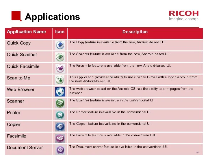
Applications
Applications
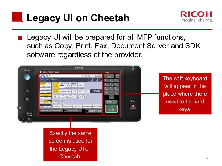
Legacy UI on Cheetah
Legacy UI will be prepared for all MFP
Legacy UI on Cheetah
Legacy UI will be prepared for all MFP
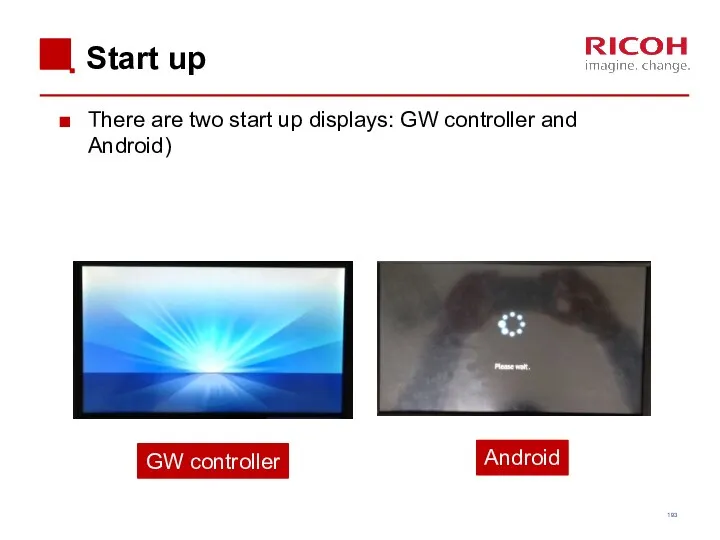
Start up
There are two start up displays: GW controller and Android)
Android
GW
Start up
There are two start up displays: GW controller and Android)
Android
GW
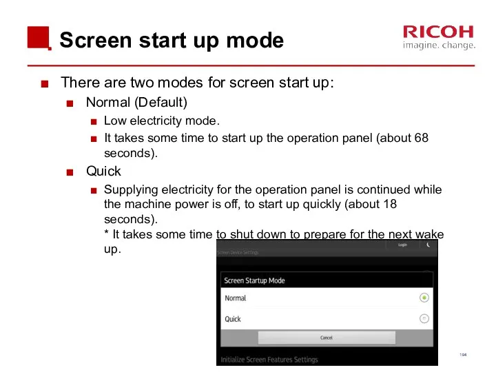
Screen start up mode
There are two modes for screen start up:
Screen start up mode
There are two modes for screen start up:
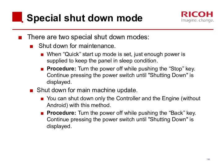
Special shut down mode
There are two special shut down modes:
Shut
Special shut down mode
There are two special shut down modes:
Shut
Service Modes
There are three SP modes.
Machine service mode
Android operation panel
Service Modes
There are three SP modes.
Machine service mode
Android operation panel
 Районирование территории России
 Презентация 3
 Where is the bed
 Противокариозные зубные пасты с кальцием и фосфором
 Проблемное обучение на уроках химии
 Методики обследования памяти в дошкольный, школьный возраст, у взрослых людей
 Археологические памятники презентация
 Исследовательская работа Хуулгаазын Дошка
 Стереотипы, их роль в процессе общения. Этика
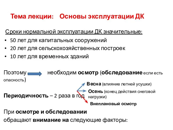 Основы эксплуатации ДК
 Сочинение по картине В. Серова Девочка с персиками
 На грани вымирания. Амурский тигр
 фізика нано лек 3. Типи кристалічних ґраток
 Миниатюрная ведущая, способная преувеличить масштаб любого события!
 Вдов солдатских нелегкие судьбы…Солдатские вдовы
 Случаи сложения вида +4
 Системы счисления
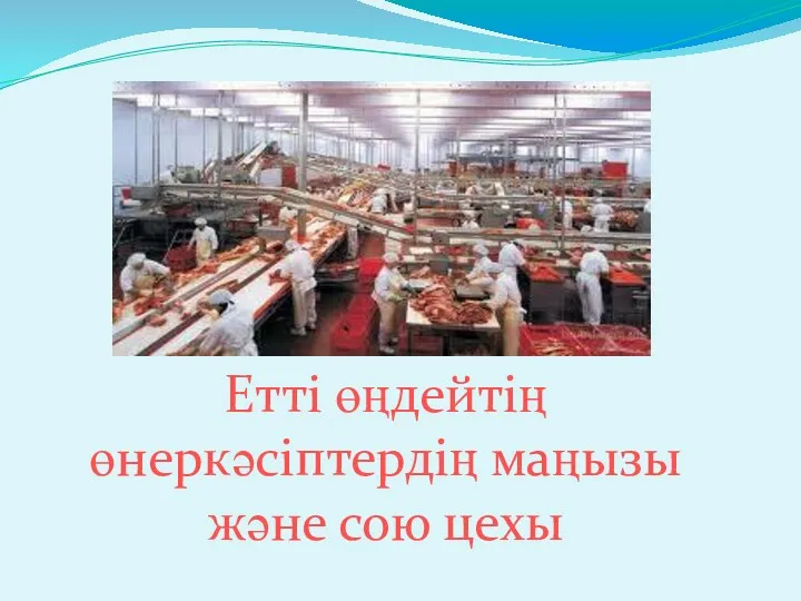 Етті өңдейтің өнеркәсіптердің маңызы және сою цехы
 Совершенствование речевого развития детей через театрализованную деятельность.
 Сочинение на тему, связанную с анализом текста (сочинение 15.2)
 Подходы к измерению информации
 Русские народные сказки. Сказители
 Методология, теория и методы психологических исследований
 Распространение дезинформации в мессенджере whatsapp и проблема ее влияния на общественное мнение
 Функции в языке программирования QBasic. Арифметические, строковые и логические выражения
 Диагностические возможности социально-психологического анамнеза в коррекции нарушений речи у детей
 Экономикалық ақпарат
 Форстеритовая и кордиеритовая керамика