- Operation instruction. MK84 series. Automatic CNC roll grinder

Содержание
- 2. Please read this instruction carefully and make sure to follow suit, including: ★NOTE: DON’T OPERATE WITHOUT
- 3. 2 NOTES BEFORE OPERATION SWITCH BETWEEN CHINESE AND ENGLISH: (1) “MENU”; (2) “SETUP”. ★BEFORE AUTOMATIC GRINDING,
- 4. 3 PREPARATIONS-WORKING ENVIRONMENT Remove objects that may impede operation; Clear the site of irrelevant personnel; Check
- 5. 3 PREPARATIONS-GRINDER STANDBY Clear all the problems after checking. Report timely if problems can’t be solved
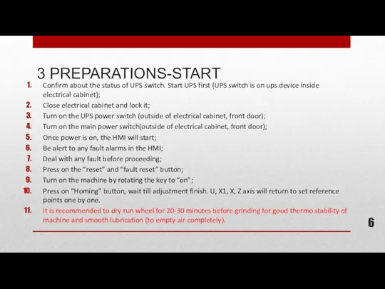
- 6. 3 PREPARATIONS-START Confirm about the status of UPS switch. Start UPS first (UPS switch is on
- 7. In case of emergency, the grinder can be shut down with pressing on an emergency button,
- 8. Firstly, please shut down the grinder completely through the key on control panel. The main power
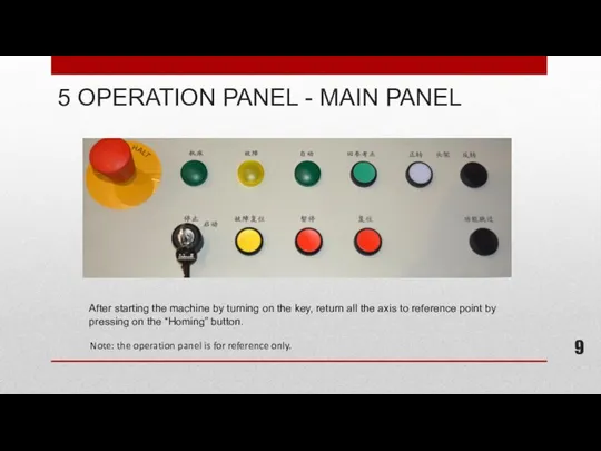
- 9. After starting the machine by turning on the key, return all the axis to reference point
- 10. ·【Emergency stop】: press in case of emergency, rotate to reset; ·【Start/stop】: key to start and stop
- 11. Explanation: Faceplate clockwise inching. Faceplate counter-clockwise inching. Faceplate extension inching. Faceplate retraction inching. Softlanding up. Softlanding
- 12. Explanation: Quill inch forward. Quill inch backward. Tailstock forward. Tailstock backward. Emergency stop. 5 OPERATION PANEL
- 13. Explanation: Quill inch forward. Quill inch backward. Tailstock forward. Tailstock backward. Emergency stop. Tailstock clamp\release buttion
- 14. Explanation: Quill inch forward. Quill inch backward. Tailstock forward. Tailstock backward. Tailstock clamp\release buttion and indication.
- 15. 6 HAND HELD CONTROL BOX INSTRUCTION Selection button: X (grinding carriage ); Y(U1/U/V adjustment); Z(carriage); 4(X1
- 16. 6 HAND HELD BOX CONTROL - NOTES Note: Improper handling of the control box may leads
- 17. 7 PREPARATION - WORKPIECE STANDBY(HARPOON TYPE CHOCK TILTING) Press on 【U1 homing】, see “8 Action Element
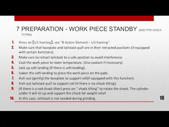
- 18. 7 PREPARATION - WORK PIECE STANDBY (ROD TYPE CHOCK TILTING) Press on 【U1 homing】, see “8
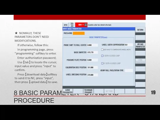
- 19. 8 BASIC PARAMETER - STANDARD PROCEDURE ★ NOMALLY, THESE PARAMETERS DON’T NEED MODIFICATIONS. If otherwise, follow
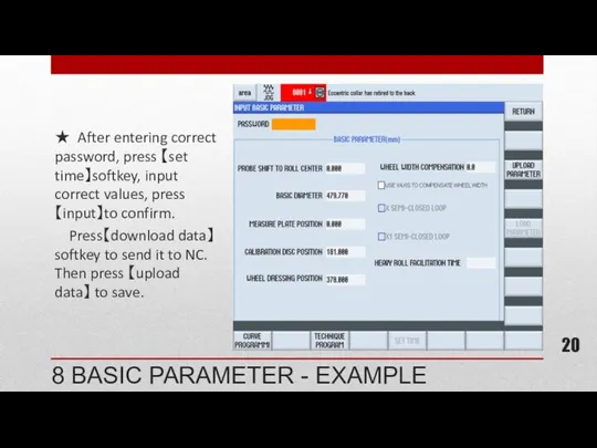
- 20. 8 BASIC PARAMETER - EXAMPLE ★ After entering correct password, press 【set time】softkey, input correct values,
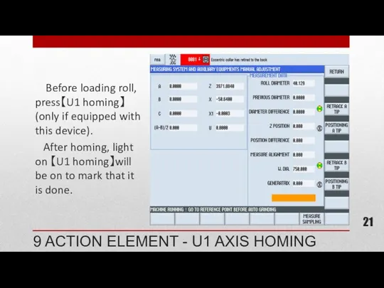
- 21. 9 ACTION ELEMENT - U1 AXIS HOMING Before loading roll, press【U1 homing】(only if equipped with this
- 22. Use 【put down arms】 and【retract arms】 softkey to operate manually. Retract X1 axis through control box
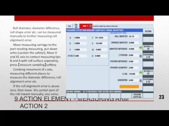
- 23. 9 ACTION ELEMENT - MEASURING ARM ACTION 2 Roll diameter, diameter difference, roll shape error etc.
- 24. PREPARATIONS - GRINDER STANDBY - CENTERLINE Measure the generatrix of roll to get a general idea
- 25. The starting page of Hiecise processing is the jog mode grinding page. In this page, use
- 26. Put down measuring arm B, move Z axis to headstock side roll surface. Adjust Z axis
- 27. 8 ACTION ELEMENT - HEAVY ROLL STARTUP In this page, operator can choose to rotate the
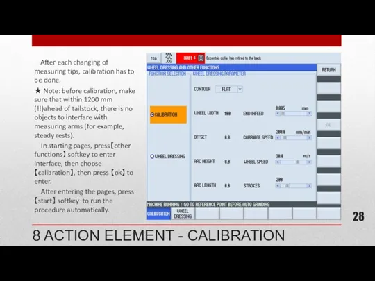
- 28. 8 ACTION ELEMENT - CALIBRATION After each changing of measuring tips, calibration has to be done.
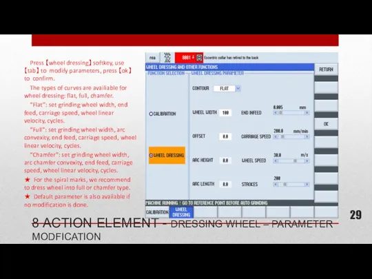
- 29. 8 ACTION ELEMENT - DRESSING WHEEL – PARAMETER MODFICATION Press 【wheel dressing】 softkey, use 【tab】 to
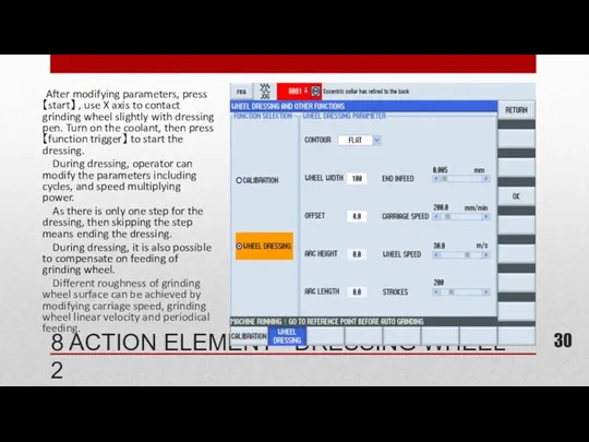
- 30. 8 ACTION ELEMENT - DRESSING WHEEL 2 After modifying parameters, press 【start】 , use X axis
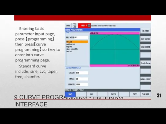
- 31. 9 CURVE PROGRAMMING - ENTERING INTERFACE Entering basic parameter input page, press 【programming】then press【curve programming】 softkey
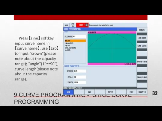
- 32. 9 CURVE PROGRAMMING - SINCE CURVE PROGRAMMING Press 【sine】 softkey, input curve name in 【curve name】,
- 33. Press 【CVC】 softkey, input curve name in【curve name】, use 【tab】 to move cursor to input “a1”,“a2”
- 34. Press 【taper】 softkey, input curve name in 【curve name】, use 【tab】 to move cursor to input
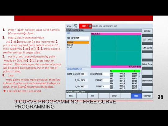
- 35. 9 CURVE PROGRAMMING - FREE CURVE PROGRAMMING Press “Taper” soft key, input curve name in【Curve name】column.
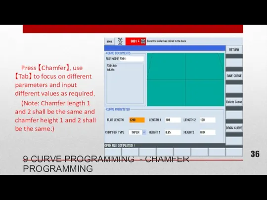
- 36. Press 【Chamfer】, use 【Tab】 to focus on different parameters and input different values as required. (Note:
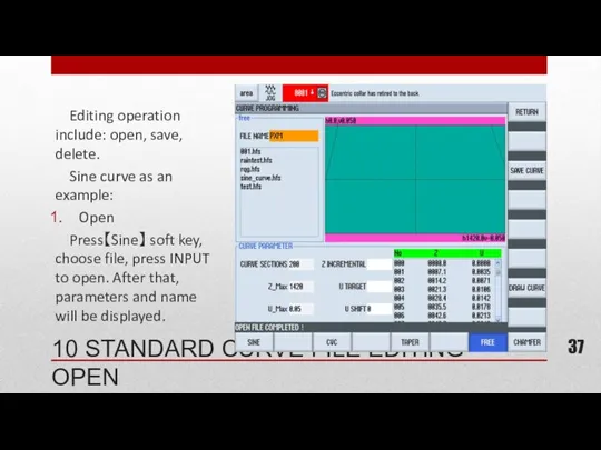
- 37. 10 STANDARD CURVE FILE EDITING - OPEN Editing operation include: open, save, delete. Sine curve as
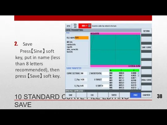
- 38. 10 STANDARD CURVE FILE EDITING - SAVE Save Press【Sine】 soft key, put in name (less than
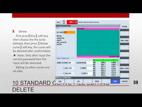
- 39. 10 STANDARD CURVE FILE EDITING - DELETE Delete First press【Sine】 soft key, then choose the file
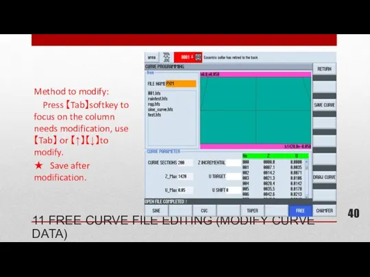
- 40. 11 FREE CURVE FILE EDITING (MODIFY CURVE DATA) Method to modify: Press 【Tab】softkey to focus on
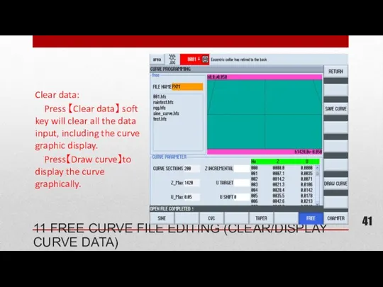
- 41. 11 FREE CURVE FILE EDITING (CLEAR/DISPLAY CURVE DATA) Clear data: Press 【Clear data】 soft key will
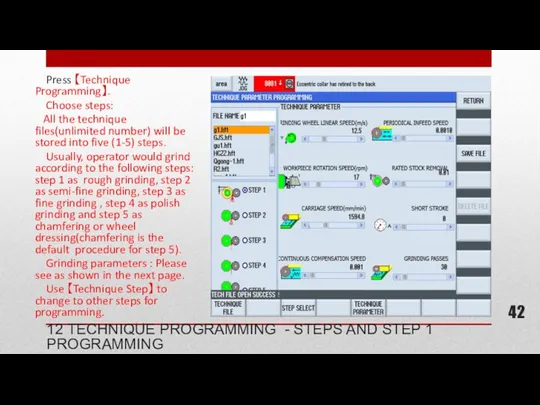
- 42. Press 【Technique Programming】. Choose steps: All the technique files(unlimited number) will be stored into five (1-5)
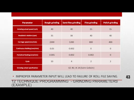
- 43. 12 TECHNIQUE PROGRAMMING - GRINDING PARAMETERS (EXAMPLE) IMPROPER PARAMETER INPUT WILL LEAD TO FAILURE OF ROLL
- 44. If short stroke (adaptive grinding) is needed, cycles of short stroke should be need. Adaptive Grinding
- 45. Press 【Technique file】 soft key to edit files(similar to curve file editing). ☆ input technique data
- 46. Roll file programming is the initial page after entering programming procedure. All the steps, techniques etc.
- 47. Press 【Roll file】soft key, use【Tab】 to switch focus to roll name column and input roll name.
- 48. Press【Select curve】soft key, use【↑】【↓】 to choose curve type. Use 【↑】【↓】 to choose the curve name and
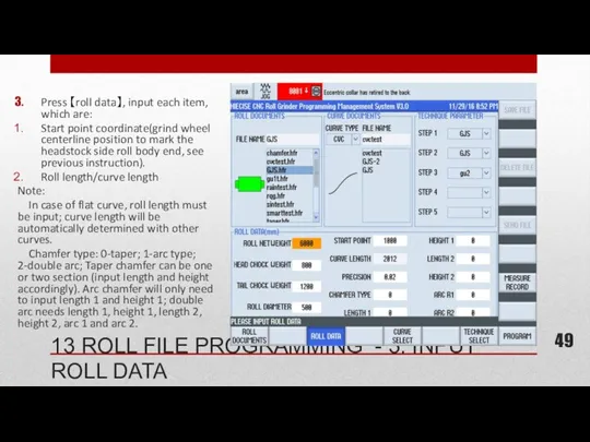
- 49. Press 【roll data】, input each item, which are: Start point coordinate(grind wheel centerline position to mark
- 50. Roll diameter. Specially notice: value input must be larger than real value(min 50 mm). Curve permissible
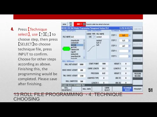
- 51. Press 【Technique select】, use 【↑】【↓】 to choose step, then press 【SELECT】to choose technique file, press INPUT
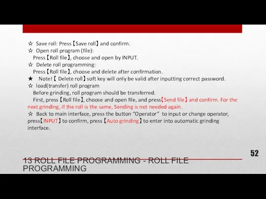
- 52. ☆ Save roll: Press 【Save roll】 and confirm. ☆ Open roll program (file): Press 【Roll file】,
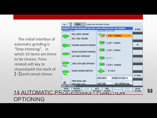
- 53. The initial interface of automatic grinding is “Step choosing”, in which 10 items are there to
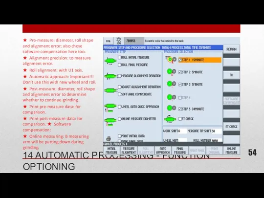
- 54. ★ Pre-measure: diameter, roll shape and alignment error; also chose software compensation here too. ★ Alignment
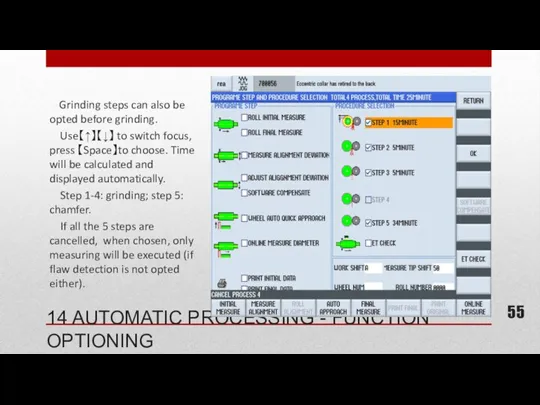
- 55. Grinding steps can also be opted before grinding. Use【↑】【↓】 to switch focus, press 【Space】to choose. Time
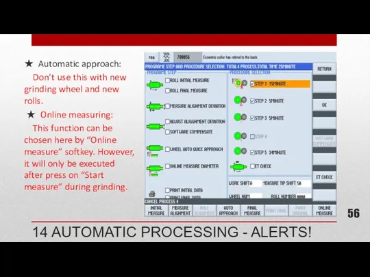
- 56. ★ Automatic approach: Don’t use this with new grinding wheel and new rolls. ★ Online measuring:
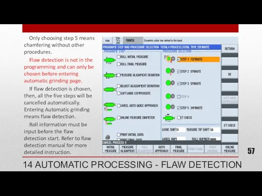
- 57. Only choosing step 5 means chamfering without other procedures. Flaw detection is not in the programming
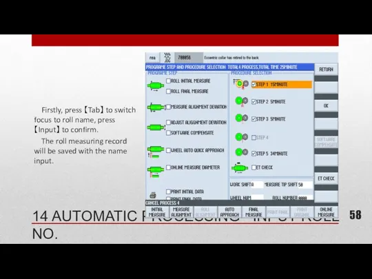
- 58. Firstly, press 【Tab】 to switch focus to roll name, press【Input】 to confirm. The roll measuring record
- 59. Press 【Tab】 to focus on 【Offset】, press【Input】 to confirm. Allowable offset range: 50 mm-500 mm. Note
- 60. Make sure roll has been placed correctly. Choose correct programs, and that the programs have been
- 61. Press 【Start】 to begin. During the automatic approaching to roll, operator can chose to press on
- 62. Halting Press 【Halt】 and confirm. Grinding wheel will retreat and work piece stops running. Press 【workpiece
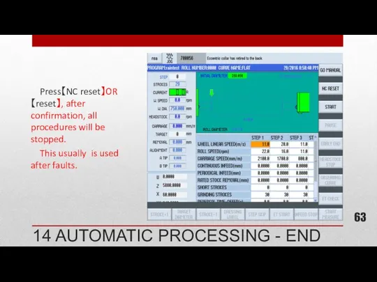
- 63. Press【NC reset】OR 【reset】, after confirmation, all procedures will be stopped. This usually is used after faults.
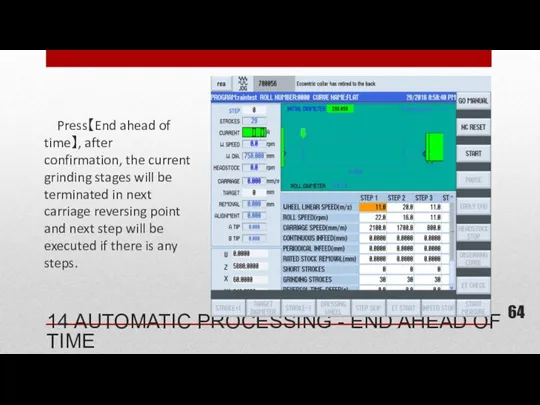
- 64. Press【End ahead of time】, after confirmation, the current grinding stages will be terminated in next carriage
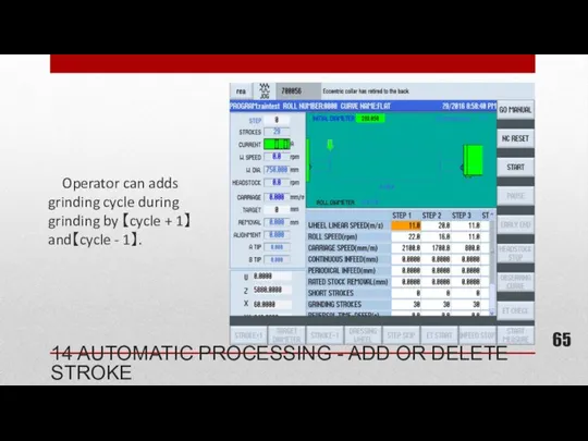
- 65. Operator can adds grinding cycle during grinding by 【cycle + 1】and【cycle - 1】. 14 AUTOMATIC PROCESSING
- 66. Press【skip step】 and confirm, the remaining cycles in the current steps will be reduced to 1,
- 67. During automatic grinding, operator can change the multiplying power of carriage movement and continuous compensation within
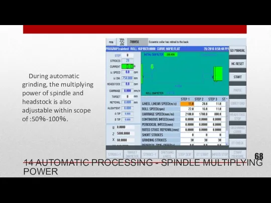
- 68. During automatic grinding, the multiplying power of spindle and headstock is also adjustable within scope of
- 69. (Only for grinders that are equipped with X1 axis) When grinding roll body, press【online measure】, grinding
- 70. During automatic grinding, operator can adjust X axis feeding in a small scale to compensate. 14
- 71. During grinding, press【dress wheel】 to enter height ( The wheel dressing can be ended ahead of
- 72. (Only for grinders without measuring system) During grinding, press【grinding interruption】, after confirmation, the carriage will retreat
- 73. After grinding, whether choosing or not, the diameter of the current grinding wheel will be measured.
- 74. Press 【observe curve】 to enter the page in which different curves(as per items on the right)
- 75. During automatic grinding, press【measure online】 and confirm. Wheel will retreat 10 mm when passing left roll
- 76. Firstly, activate the function by choosing the function on flaw detection interface, input roll information and
- 77. If the grinding current exceed the set amount for 5 second and more, grinder will shut
- 78. Dry run grinding wheel for at least 5 minutes before shutting down grinder; Note: Make sure
- 80. Скачать презентацию
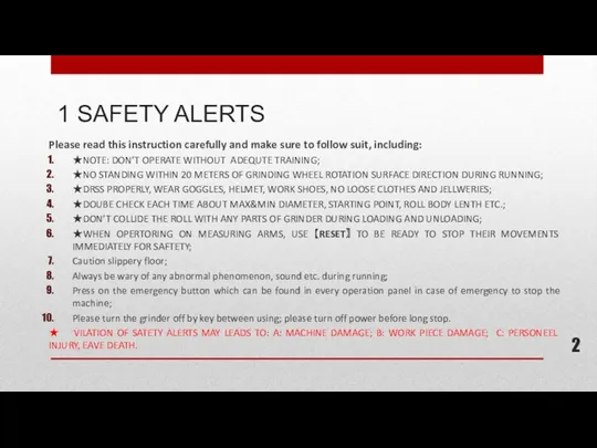
Please read this instruction carefully and make sure to follow suit,
Please read this instruction carefully and make sure to follow suit,
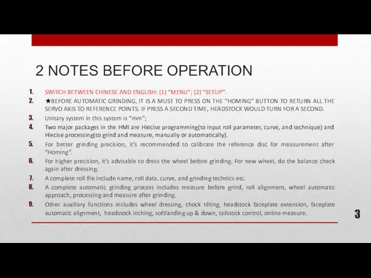
2 NOTES BEFORE OPERATION
SWITCH BETWEEN CHINESE AND ENGLISH: (1) “MENU”; (2)
2 NOTES BEFORE OPERATION
SWITCH BETWEEN CHINESE AND ENGLISH: (1) “MENU”; (2)
3 PREPARATIONS-WORKING ENVIRONMENT
Remove objects that may impede operation;
Clear the site of
3 PREPARATIONS-WORKING ENVIRONMENT
Remove objects that may impede operation;
Clear the site of
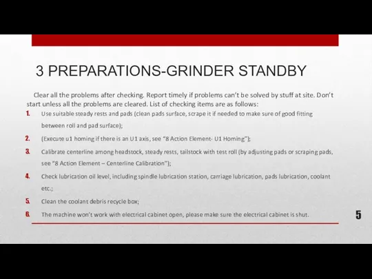
3 PREPARATIONS-GRINDER STANDBY
Clear all the problems after checking. Report timely
3 PREPARATIONS-GRINDER STANDBY
Clear all the problems after checking. Report timely
3 PREPARATIONS-START
Confirm about the status of UPS switch. Start UPS first
3 PREPARATIONS-START
Confirm about the status of UPS switch. Start UPS first
In case of emergency, the grinder can be shut down
In case of emergency, the grinder can be shut down
Firstly, please shut down the grinder completely through the key
Firstly, please shut down the grinder completely through the key
After starting the machine by turning on the key, return all
After starting the machine by turning on the key, return all
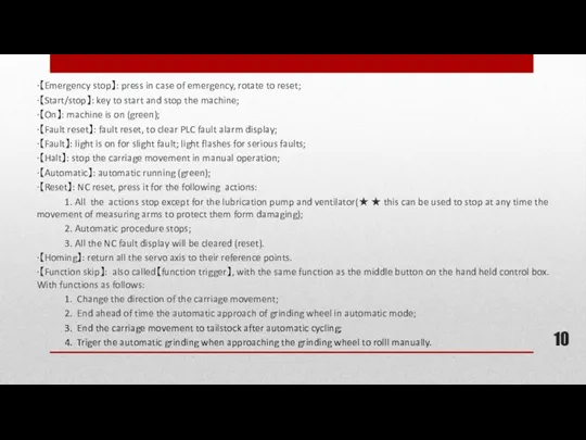
·【Emergency stop】: press in case of emergency, rotate to reset;
·【Start/stop】: key
·【Emergency stop】: press in case of emergency, rotate to reset;
·【Start/stop】: key
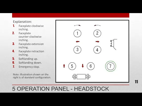
Explanation:
Faceplate clockwise inching.
Faceplate counter-clockwise inching.
Faceplate extension inching.
Faceplate retraction inching.
Softlanding up.
Softlanding down.
Emergency
Explanation:
Faceplate clockwise inching.
Faceplate counter-clockwise inching.
Faceplate extension inching.
Faceplate retraction inching.
Softlanding up.
Softlanding down.
Emergency
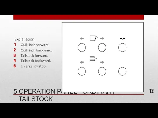
Explanation:
Quill inch forward.
Quill inch backward.
Tailstock forward.
Tailstock backward.
Emergency stop.
5 OPERATION PANEL -
Explanation:
Quill inch forward.
Quill inch backward.
Tailstock forward.
Tailstock backward.
Emergency stop.
5 OPERATION PANEL -
Explanation:
Quill inch forward.
Quill inch backward.
Tailstock forward.
Tailstock backward.
Emergency stop.
Tailstock clamp\release buttion and
Explanation:
Quill inch forward.
Quill inch backward.
Tailstock forward.
Tailstock backward.
Emergency stop.
Tailstock clamp\release buttion and
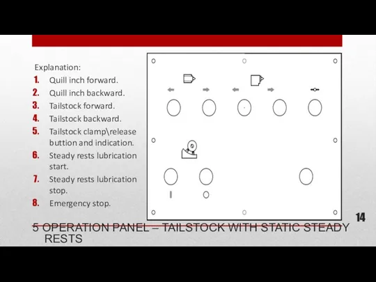
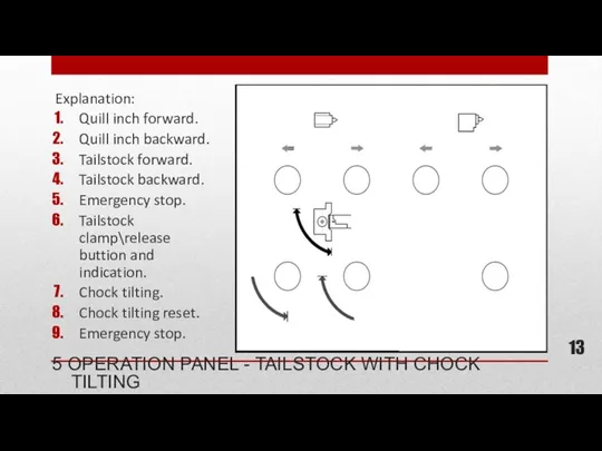
Explanation:
Quill inch forward.
Quill inch backward.
Tailstock forward.
Tailstock backward.
Tailstock clamp\release buttion and indication.
Steady
Explanation:
Quill inch forward.
Quill inch backward.
Tailstock forward.
Tailstock backward.
Tailstock clamp\release buttion and indication.
Steady
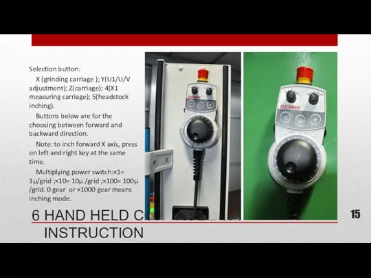
6 HAND HELD CONTROL BOX INSTRUCTION
Selection button:
X (grinding carriage );
6 HAND HELD CONTROL BOX INSTRUCTION
Selection button:
X (grinding carriage );
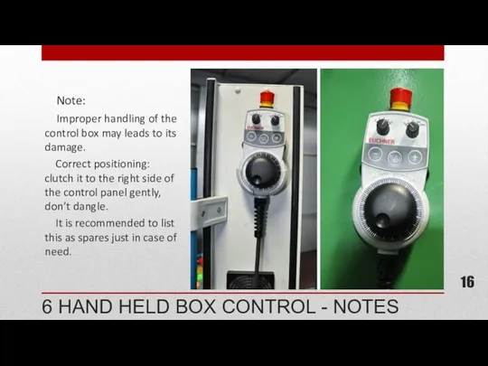
6 HAND HELD BOX CONTROL - NOTES
Note:
Improper handling
6 HAND HELD BOX CONTROL - NOTES
Note:
Improper handling
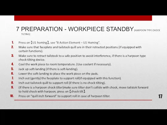
7 PREPARATION - WORKPIECE STANDBY(HARPOON TYPE CHOCK TILTING)
Press on 【U1 homing】,
7 PREPARATION - WORKPIECE STANDBY(HARPOON TYPE CHOCK TILTING)
Press on 【U1 homing】,
7 PREPARATION - WORK PIECE STANDBY (ROD TYPE CHOCK TILTING)
Press on
7 PREPARATION - WORK PIECE STANDBY (ROD TYPE CHOCK TILTING)
Press on
8 BASIC PARAMETER - STANDARD PROCEDURE
★ NOMALLY, THESE PARAMETERS DON’T NEED
8 BASIC PARAMETER - STANDARD PROCEDURE
★ NOMALLY, THESE PARAMETERS DON’T NEED
8 BASIC PARAMETER - EXAMPLE
★ After entering correct password, press 【set
8 BASIC PARAMETER - EXAMPLE
★ After entering correct password, press 【set
9 ACTION ELEMENT - U1 AXIS HOMING
Before loading roll, press【U1
9 ACTION ELEMENT - U1 AXIS HOMING
Before loading roll, press【U1
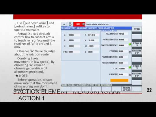
Use 【put down arms】 and【retract arms】 softkey to operate manually.
Use 【put down arms】 and【retract arms】 softkey to operate manually.
9 ACTION ELEMENT - MEASURING ARM ACTION 2
Roll diameter, diameter
9 ACTION ELEMENT - MEASURING ARM ACTION 2
Roll diameter, diameter
PREPARATIONS - GRINDER STANDBY - CENTERLINE
Measure the generatrix of roll to
PREPARATIONS - GRINDER STANDBY - CENTERLINE
Measure the generatrix of roll to
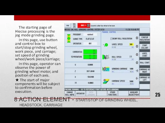
The starting page of Hiecise processing is the jog mode
The starting page of Hiecise processing is the jog mode
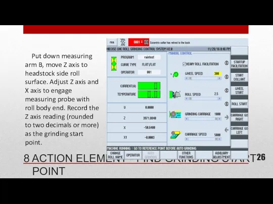
Put down measuring arm B, move Z axis to headstock
Put down measuring arm B, move Z axis to headstock

8 ACTION ELEMENT - HEAVY ROLL STARTUP
In this page, operator
8 ACTION ELEMENT - HEAVY ROLL STARTUP
In this page, operator
8 ACTION ELEMENT - CALIBRATION
After each changing of measuring tips,
8 ACTION ELEMENT - CALIBRATION
After each changing of measuring tips,
8 ACTION ELEMENT - DRESSING WHEEL – PARAMETER MODFICATION
Press 【wheel
8 ACTION ELEMENT - DRESSING WHEEL – PARAMETER MODFICATION
Press 【wheel
8 ACTION ELEMENT - DRESSING WHEEL 2
After modifying parameters, press
8 ACTION ELEMENT - DRESSING WHEEL 2
After modifying parameters, press
9 CURVE PROGRAMMING - ENTERING INTERFACE
Entering basic parameter input page,
9 CURVE PROGRAMMING - ENTERING INTERFACE
Entering basic parameter input page,
9 CURVE PROGRAMMING - SINCE CURVE PROGRAMMING
Press 【sine】 softkey, input
9 CURVE PROGRAMMING - SINCE CURVE PROGRAMMING
Press 【sine】 softkey, input
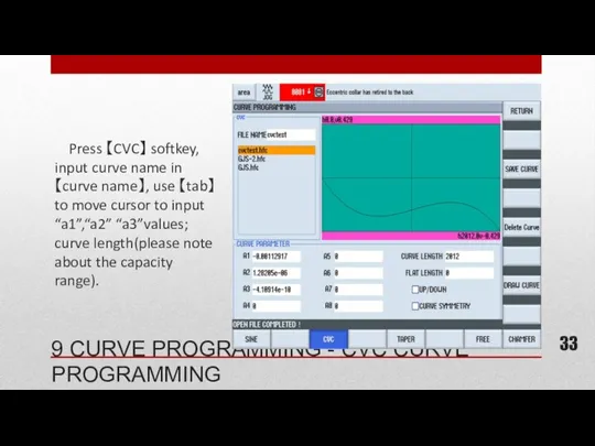
Press 【CVC】 softkey, input curve name in【curve name】, use 【tab】
Press 【CVC】 softkey, input curve name in【curve name】, use 【tab】
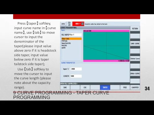
Press 【taper】 softkey, input curve name in 【curve name】, use
Press 【taper】 softkey, input curve name in 【curve name】, use
9 CURVE PROGRAMMING - FREE CURVE PROGRAMMING
Press “Taper” soft key, input
9 CURVE PROGRAMMING - FREE CURVE PROGRAMMING
Press “Taper” soft key, input
Press 【Chamfer】, use 【Tab】 to focus on different parameters and
Press 【Chamfer】, use 【Tab】 to focus on different parameters and
10 STANDARD CURVE FILE EDITING - OPEN
Editing operation include: open,
10 STANDARD CURVE FILE EDITING - OPEN
Editing operation include: open,
10 STANDARD CURVE FILE EDITING - SAVE
Save
Press【Sine】 soft key, put
10 STANDARD CURVE FILE EDITING - SAVE
Save
Press【Sine】 soft key, put
10 STANDARD CURVE FILE EDITING - DELETE
Delete
First press【Sine】 soft key,
10 STANDARD CURVE FILE EDITING - DELETE
Delete
First press【Sine】 soft key,
11 FREE CURVE FILE EDITING (MODIFY CURVE DATA)
Method to modify:
Press
11 FREE CURVE FILE EDITING (MODIFY CURVE DATA)
Method to modify:
Press
11 FREE CURVE FILE EDITING (CLEAR/DISPLAY CURVE DATA)
Clear data:
Press 【Clear
11 FREE CURVE FILE EDITING (CLEAR/DISPLAY CURVE DATA)
Clear data:
Press 【Clear
Press 【Technique Programming】.
Choose steps:
All the technique files(unlimited number)
Press 【Technique Programming】.
Choose steps:
All the technique files(unlimited number)
12 TECHNIQUE PROGRAMMING - GRINDING PARAMETERS (EXAMPLE)
IMPROPER PARAMETER INPUT WILL LEAD
12 TECHNIQUE PROGRAMMING - GRINDING PARAMETERS (EXAMPLE)
IMPROPER PARAMETER INPUT WILL LEAD
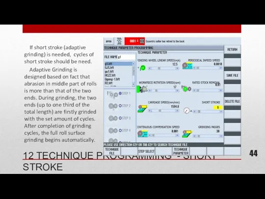
If short stroke (adaptive grinding) is needed, cycles of short
If short stroke (adaptive grinding) is needed, cycles of short
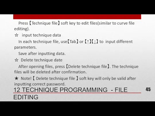
Press 【Technique file】 soft key to edit files(similar to curve
Press 【Technique file】 soft key to edit files(similar to curve
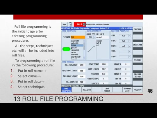
Roll file programming is the initial page after entering programming
Roll file programming is the initial page after entering programming
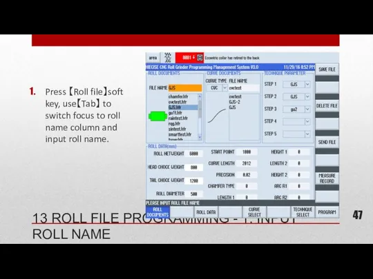
Press 【Roll file】soft key, use【Tab】 to switch focus to roll name
Press 【Roll file】soft key, use【Tab】 to switch focus to roll name
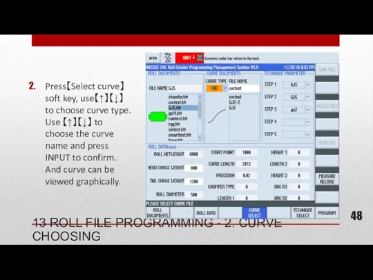
Press【Select curve】soft key, use【↑】【↓】 to choose curve type. Use 【↑】【↓】 to
Press【Select curve】soft key, use【↑】【↓】 to choose curve type. Use 【↑】【↓】 to
Press 【roll data】, input each item, which are:
Start point coordinate(grind wheel
Press 【roll data】, input each item, which are:
Start point coordinate(grind wheel
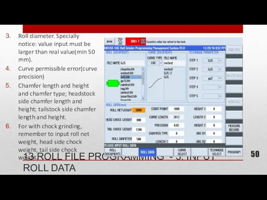
Roll diameter. Specially notice: value input must be larger than real
Roll diameter. Specially notice: value input must be larger than real
Press 【Technique select】, use 【↑】【↓】 to choose step, then press 【SELECT】to
Press 【Technique select】, use 【↑】【↓】 to choose step, then press 【SELECT】to
☆ Save roll: Press 【Save roll】 and confirm.
☆ Open roll program
☆ Save roll: Press 【Save roll】 and confirm.
☆ Open roll program
The initial interface of automatic grinding is “Step choosing”, in
The initial interface of automatic grinding is “Step choosing”, in
★ Pre-measure: diameter, roll shape and alignment error; also chose software
★ Pre-measure: diameter, roll shape and alignment error; also chose software
Grinding steps can also be opted before grinding.
Use【↑】【↓】 to
Grinding steps can also be opted before grinding.
Use【↑】【↓】 to
★ Automatic approach:
Don’t use this with new grinding wheel
★ Automatic approach:
Don’t use this with new grinding wheel
Only choosing step 5 means chamfering without other procedures.
Flaw
Only choosing step 5 means chamfering without other procedures.
Flaw
Firstly, press 【Tab】 to switch focus to roll name, press【Input】
Firstly, press 【Tab】 to switch focus to roll name, press【Input】
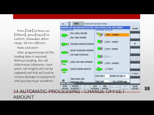
Press 【Tab】 to focus on 【Offset】, press【Input】 to confirm. Allowable
Press 【Tab】 to focus on 【Offset】, press【Input】 to confirm. Allowable
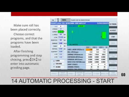
Make sure roll has been placed correctly.
Choose correct programs,
Make sure roll has been placed correctly.
Choose correct programs,
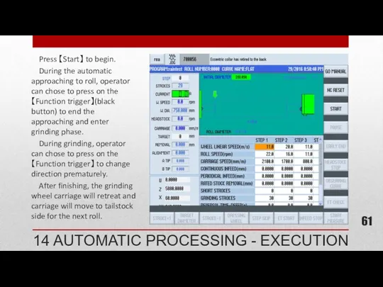
Press 【Start】 to begin.
During the automatic approaching to roll,
Press 【Start】 to begin.
During the automatic approaching to roll,
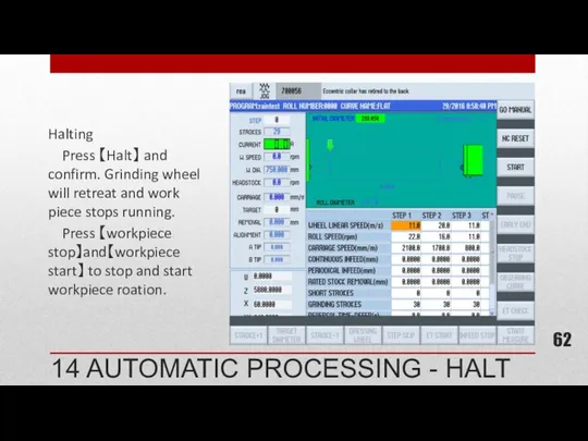
Halting
Press 【Halt】 and confirm. Grinding wheel will retreat and work
Halting
Press 【Halt】 and confirm. Grinding wheel will retreat and work
Press【NC reset】OR 【reset】, after confirmation, all procedures will be stopped.
Press【NC reset】OR 【reset】, after confirmation, all procedures will be stopped.
Press【End ahead of time】, after confirmation, the current grinding stages
Press【End ahead of time】, after confirmation, the current grinding stages
Operator can adds grinding cycle during grinding by 【cycle +
Operator can adds grinding cycle during grinding by 【cycle +

Press【skip step】 and confirm, the remaining cycles in the current
Press【skip step】 and confirm, the remaining cycles in the current

During automatic grinding, operator can change the multiplying power of
During automatic grinding, operator can change the multiplying power of
During automatic grinding, the multiplying power of spindle and headstock
During automatic grinding, the multiplying power of spindle and headstock
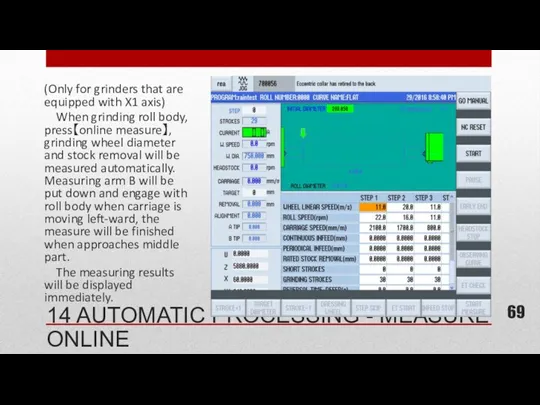
(Only for grinders that are equipped with X1 axis)
When grinding
(Only for grinders that are equipped with X1 axis)
When grinding
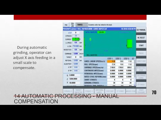
During automatic grinding, operator can adjust X axis feeding in
During automatic grinding, operator can adjust X axis feeding in
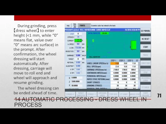
During grinding, press【dress wheel】 to enter height (<1 mm, while
During grinding, press【dress wheel】 to enter height (<1 mm, while

(Only for grinders without measuring system)
During grinding, press【grinding interruption】, after
(Only for grinders without measuring system)
During grinding, press【grinding interruption】, after
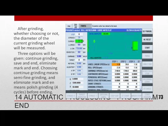
After grinding, whether choosing or not, the diameter of the
After grinding, whether choosing or not, the diameter of the
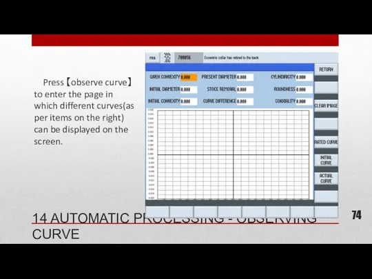
Press 【observe curve】 to enter the page in which different
Press 【observe curve】 to enter the page in which different
During automatic grinding, press【measure online】 and confirm. Wheel will retreat
During automatic grinding, press【measure online】 and confirm. Wheel will retreat
Firstly, activate the function by choosing the function on flaw
Firstly, activate the function by choosing the function on flaw
If the grinding current exceed the set amount for 5
If the grinding current exceed the set amount for 5
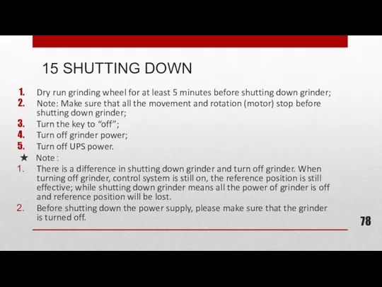
Dry run grinding wheel for at least 5 minutes before shutting
Dry run grinding wheel for at least 5 minutes before shutting
 СЕМЬЯ И ОБЩЕОБРАЗОВАТЕЛЬНОЕ УЧРЕЖДЕНИЕ -ПАРТНЁРЫ В ВОСПИТАНИИ РЕБЁНКА.
 Числит+сущ в Т.п
 Самоанализ внеклассного мероприятия Моя любимая семья
 RC Service Manual HD3033, HD3039, HD3036, HD3037, HD3077
 Подвесной потолок
 Инновационная экономика и технологическое предпринимательство
 Архитектура персонального компьютера
 Жыныс қатынасынан жұғатын аурулар
 Пауки-древнейшие обитатели нашей планеты
 Бремя доказательства. Аргументы. Работа по экономическому праву
 Долг и совесть. 8 класс
 Светоотражающие наклейки на одежде
 Бақытжан Бейсалыүлы Каратаев
 20230925_kartochki
 Новый Год
 144 года Самарскому знамени
 Сочинение по картине И.Я. Билибина Иван-царевич и лягушка-квакушка
 Самоуправление. Копилка старшего вожатого.
 Палестина - батьківщина християнства та іудаїзму
 Основы журналистики
 Послеродовые гнойно-септические заболевания
 Анатомия + Хирургические доступы к Поджелудочной железе
 Открываем Родину вместе (из опыта работы учителя начальных классов)
 Развитие артикуляционной моторики у детей с тяжелыми нарушениями речи
 Властивості складних систем. Біосфера. Основні положення В. І. Вернадського про біосферу
 Искусство и духовная жизнь
 Микронасосы. Принцип действия микронасосов
 Организация и проведение мероприятий по воспроизводству лесов и лесоразведению