- PDP Training Manual. P450

Содержание
- 2. 1. P450 Training 2. Disassembly 3. Trouble shooting 4.Appendix -. PC Timming -. 3D Function Agenda
- 3. 1. PB450 Training
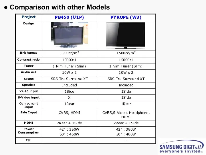
- 4. ● Comparison with other Models
- 5. ● Picture of PS50B450 Set [Back view]
- 6. ● Picture of P450 42” U1P PDP Module [Back view]
- 7. ● Picture of P450 50” U1P PDP Module [Back view]
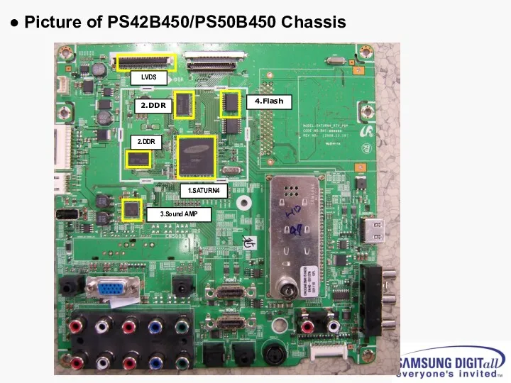
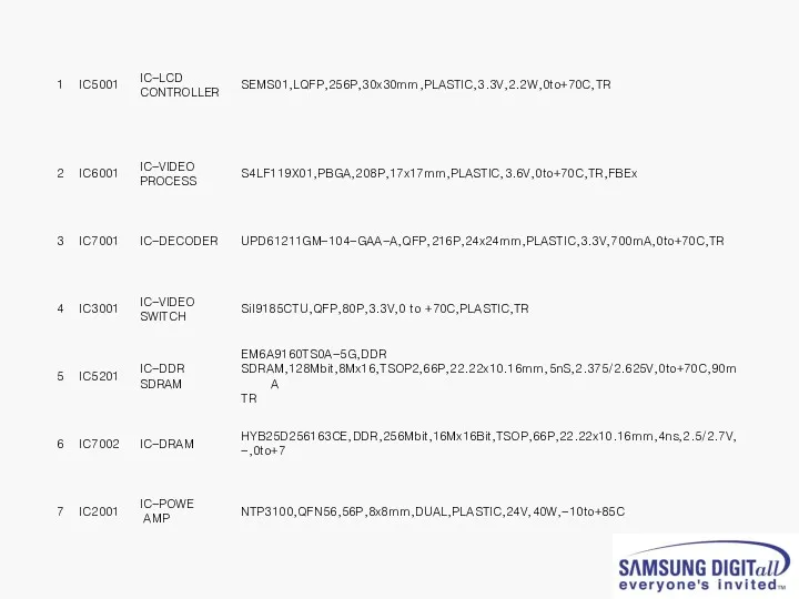
- 8. ● Picture of PS42B450/PS50B450 Chassis 1.SATURN4 2.DDR 2.DDR 3.Sound AMP LVDS 4.Flash
- 10. ● Calibration (Component/HDMI/AV/PC) ■ White Balance – Calibration If picture color is wrong, do calibration first.
- 11. ● White Balance Adjustment The WB specification can be found on the G-TMS system.
- 12. ● Picture condition in Factory mode / during WB adjust ● Factory mode OSD
- 17. Accessories
- 18. 2. Disassembly
- 19. Separation of ASSY COVER P-REAR
- 20. Separation of ASSY PCB MISC-MAIN
- 21. Separation of FILTER-EMI AC LINE
- 22. Separation of BRACKET-PCB
- 23. Separation of ASSY BRACKET 42"/50"
- 24. Separation of ASSY BRACKET P-WALL
- 25. Separation of ASSY SPEAKER P
- 26. Separation of SMPS-PDP TV
- 27. Separation of ASSY PDP MODULE P-LOGIC MAIN BOARD
- 28. Separation of ASSY PDP MODULE P-X MAIN BOARD
- 29. Separation of ASSY PDP MODULE P-X MAIN BOARD
- 30. Separation of ASSY PDP MODULE P-Y MAIN BOARD
- 31. Separation of ASSY PDP MODULE P-Y MAIN BOARD
- 32. Separation of ASSY PDP MODULE P-Y MAIN BOARD
- 33. Separation of ASSY PDP MODULE P-ADDRESS BUFFER BOARD
- 34. Separation of ASSY PANEL BRACKETS
- 35. 3. Trouble shooting
- 36. ● PS50A450 SW update method using the D/L jig D-SUB Cable 1. Connect the PC and
- 37. 3. Click “Connect” button 4. Now the connection with the SET is established. Click the “확인”
- 38. 5. Connect the Power cord and click “Read” 6. Click the new “Read” button
- 39. 7. Select the upgrade file
- 40. 8. Click “Auto” button, uncheck the Blank and Verify options and click “Run”
- 41. 9. The download progress bar appears and D/L information is shown in the info window
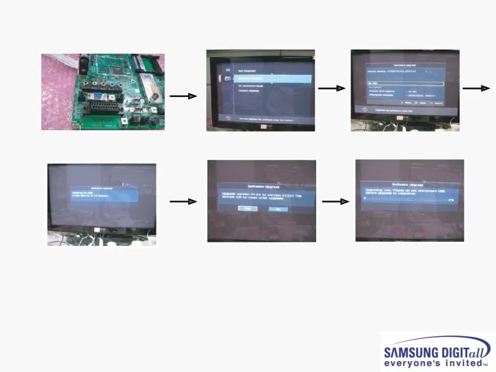
- 42. ● PS50A450 SW update method using the USB
- 44. ● Check List in advance ■. Each cable connection condition check - Cable is connected correctly
- 45. ● No Power - Not operate front LED Not operate SMPS relay
- 46. ● SMPS relay on off continually Operate Protection circuit because of some Ass’y problem
- 47. ● No display but sound is normal X or Y or Logic or Y Buffer board
- 48. ● No sound but display is normal Speaker wire is not connect Video main board sound
- 49. ● PDP Dot Module SPEC – SDI module ※ Special Management Items 1) It is Cell-Defect
- 50. ● A-Zone / B–Zone Size
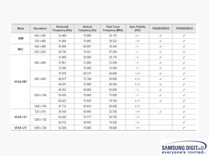
- 51. PC timming
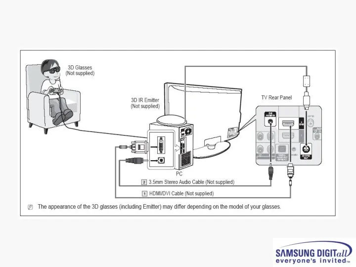
- 53. 3D Function
- 56. Скачать презентацию
1. P450 Training
2. Disassembly
3. Trouble shooting
4.Appendix
-. PC Timming
-.
1. P450 Training
2. Disassembly
3. Trouble shooting
4.Appendix
-. PC Timming
-.
1. PB450 Training
1. PB450 Training
● Comparison with other Models
● Comparison with other Models
![● Picture of PS50B450 Set [Back view]](/_ipx/f_webp&q_80&fit_contain&s_1440x1080/imagesDir/jpg/22229/slide-4.jpg)
● Picture of PS50B450 Set [Back view]
● Picture of PS50B450 Set [Back view]
![● Picture of P450 42” U1P PDP Module [Back view]](/_ipx/f_webp&q_80&fit_contain&s_1440x1080/imagesDir/jpg/22229/slide-5.jpg)
● Picture of P450 42” U1P PDP Module [Back view]
● Picture of P450 42” U1P PDP Module [Back view]
![● Picture of P450 50” U1P PDP Module [Back view]](/_ipx/f_webp&q_80&fit_contain&s_1440x1080/imagesDir/jpg/22229/slide-6.jpg)
● Picture of P450 50” U1P PDP Module [Back view]
● Picture of P450 50” U1P PDP Module [Back view]
● Picture of PS42B450/PS50B450 Chassis
1.SATURN4
2.DDR
2.DDR
3.Sound AMP
LVDS
4.Flash
● Picture of PS42B450/PS50B450 Chassis
1.SATURN4
2.DDR
2.DDR
3.Sound AMP
LVDS
4.Flash
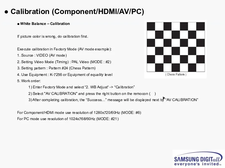
● Calibration (Component/HDMI/AV/PC)
■ White Balance – Calibration
If picture color is wrong,
● Calibration (Component/HDMI/AV/PC)
■ White Balance – Calibration
If picture color is wrong,
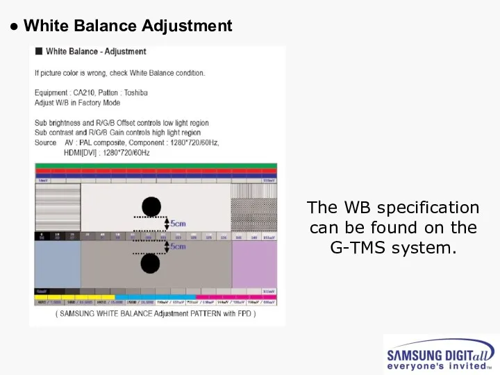
● White Balance Adjustment
The WB specification can be found on the
● White Balance Adjustment
The WB specification can be found on the
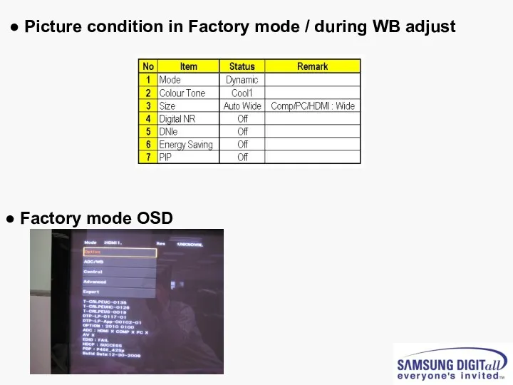
● Picture condition in Factory mode / during WB adjust
● Factory
● Picture condition in Factory mode / during WB adjust
● Factory
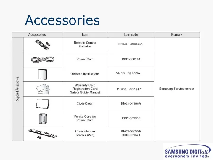
Accessories
Accessories
2. Disassembly
2. Disassembly
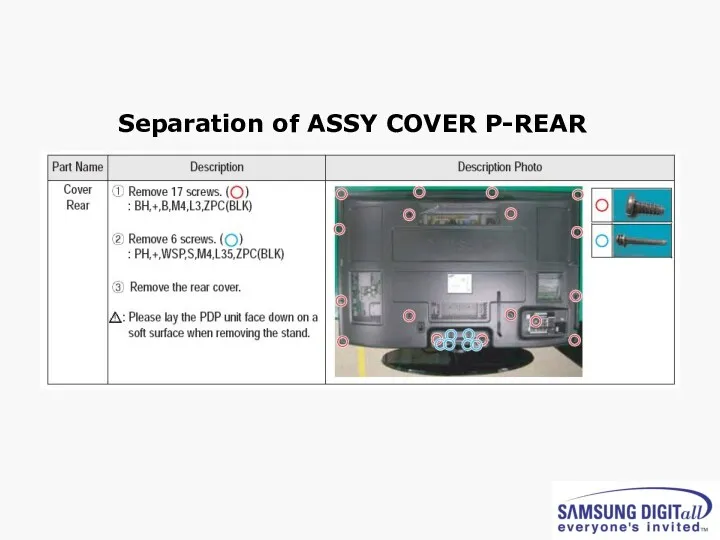
Separation of ASSY COVER P-REAR
Separation of ASSY COVER P-REAR
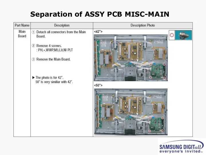
Separation of ASSY PCB MISC-MAIN
Separation of ASSY PCB MISC-MAIN
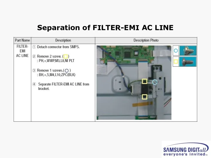
Separation of FILTER-EMI AC LINE
Separation of FILTER-EMI AC LINE
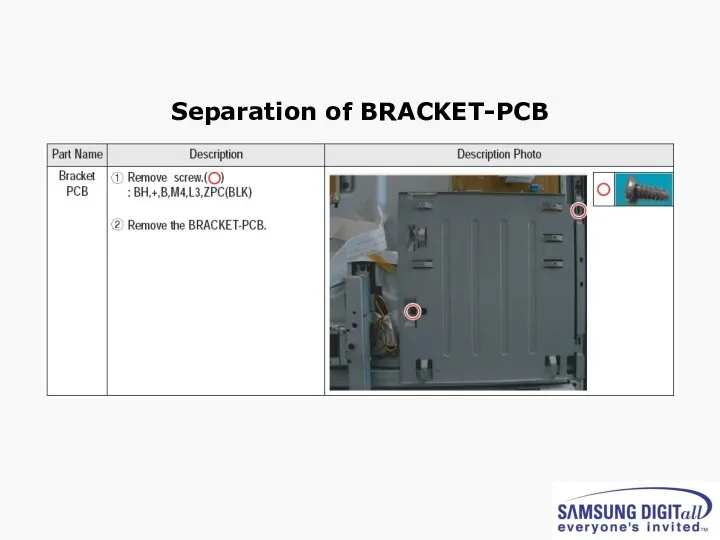
Separation of BRACKET-PCB
Separation of BRACKET-PCB
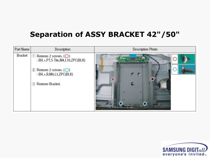
Separation of ASSY BRACKET 42"/50"
Separation of ASSY BRACKET 42"/50"
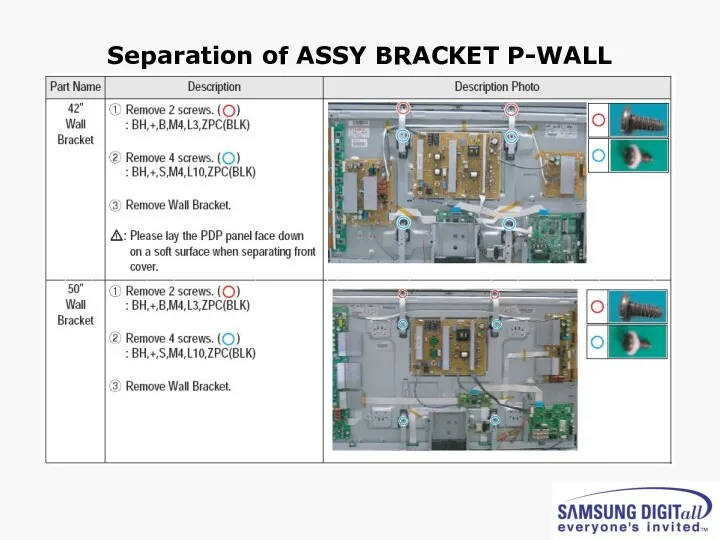
Separation of ASSY BRACKET P-WALL
Separation of ASSY BRACKET P-WALL
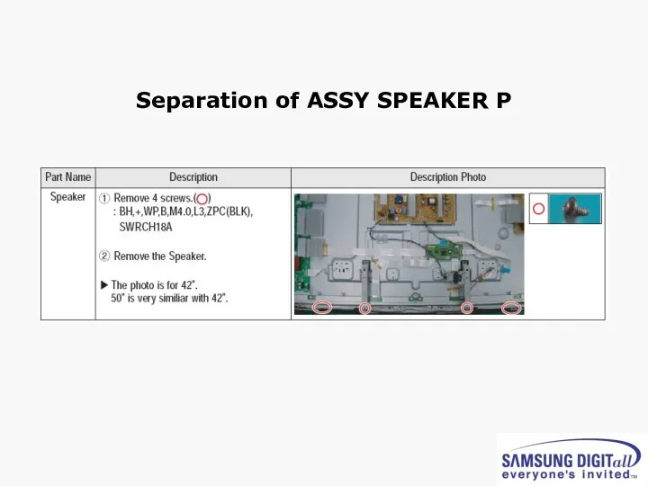
Separation of ASSY SPEAKER P
Separation of ASSY SPEAKER P
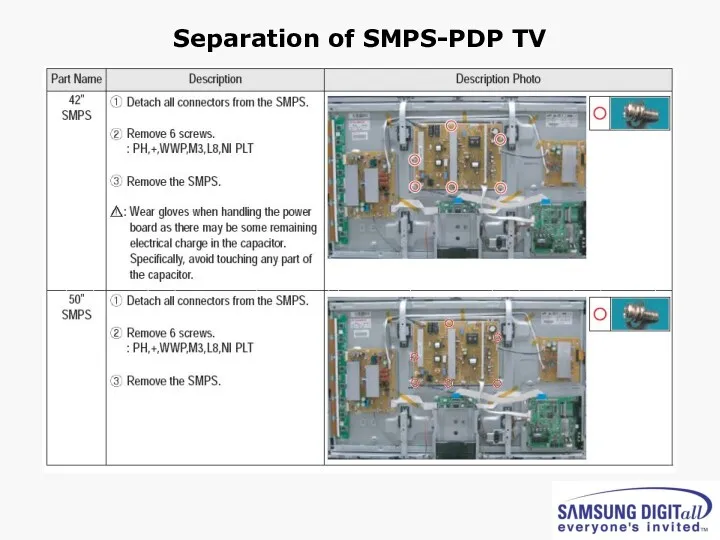
Separation of SMPS-PDP TV
Separation of SMPS-PDP TV
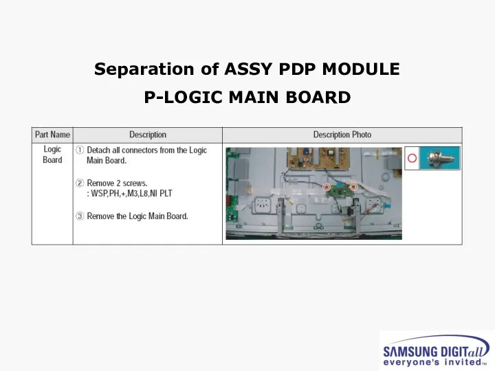
Separation of ASSY PDP MODULE
P-LOGIC MAIN BOARD
Separation of ASSY PDP MODULE
P-LOGIC MAIN BOARD
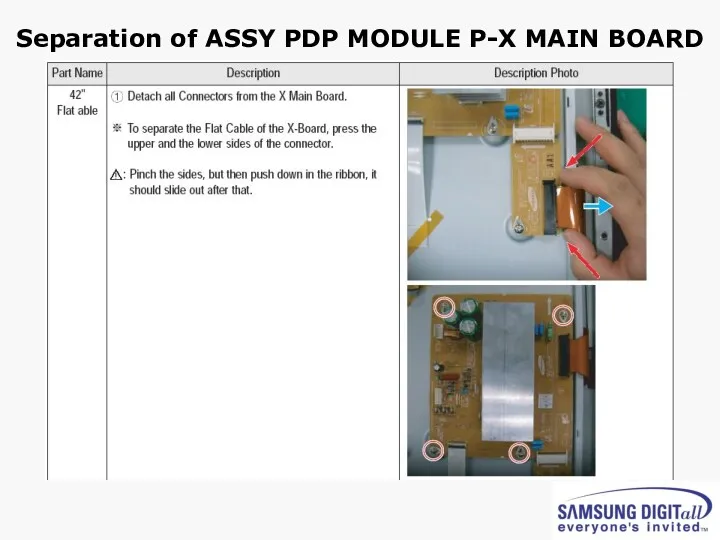
Separation of ASSY PDP MODULE P-X MAIN BOARD
Separation of ASSY PDP MODULE P-X MAIN BOARD
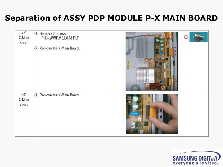
Separation of ASSY PDP MODULE P-X MAIN BOARD
Separation of ASSY PDP MODULE P-X MAIN BOARD
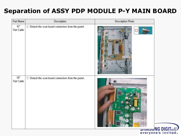
Separation of ASSY PDP MODULE P-Y MAIN BOARD
Separation of ASSY PDP MODULE P-Y MAIN BOARD
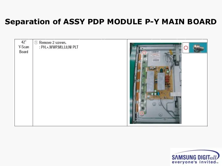
Separation of ASSY PDP MODULE P-Y MAIN BOARD
Separation of ASSY PDP MODULE P-Y MAIN BOARD
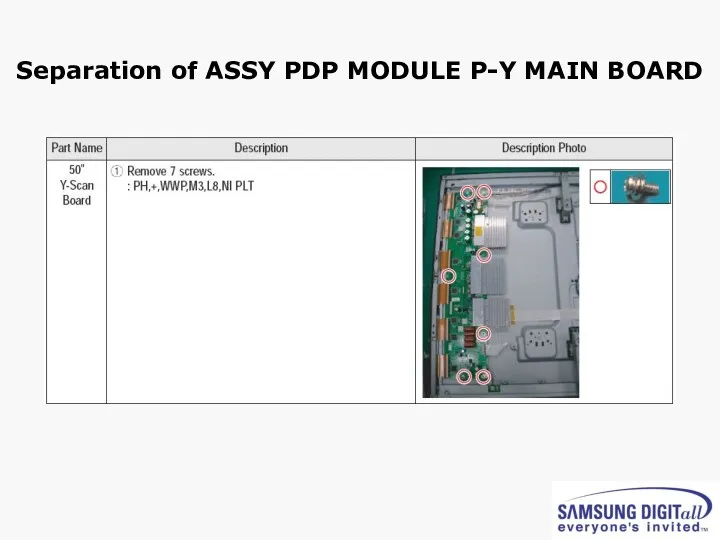
Separation of ASSY PDP MODULE P-Y MAIN BOARD
Separation of ASSY PDP MODULE P-Y MAIN BOARD
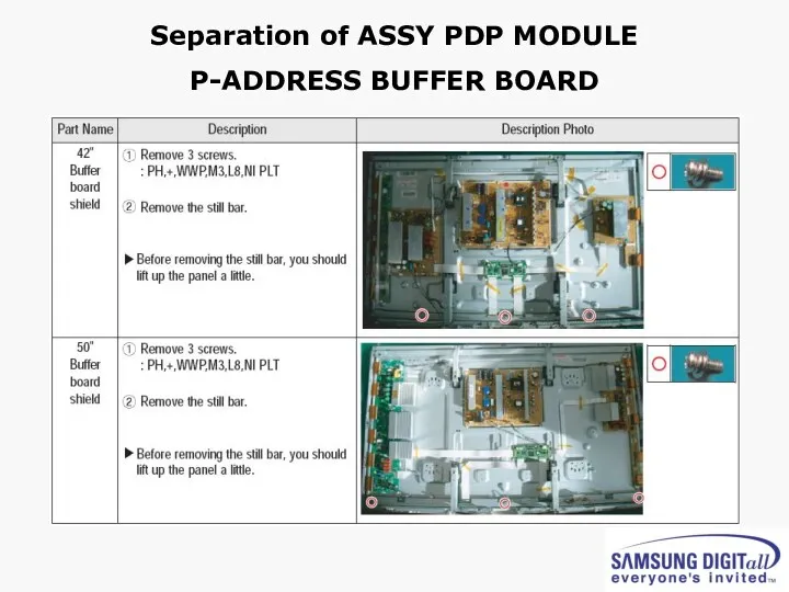
Separation of ASSY PDP MODULE
P-ADDRESS BUFFER BOARD
Separation of ASSY PDP MODULE
P-ADDRESS BUFFER BOARD
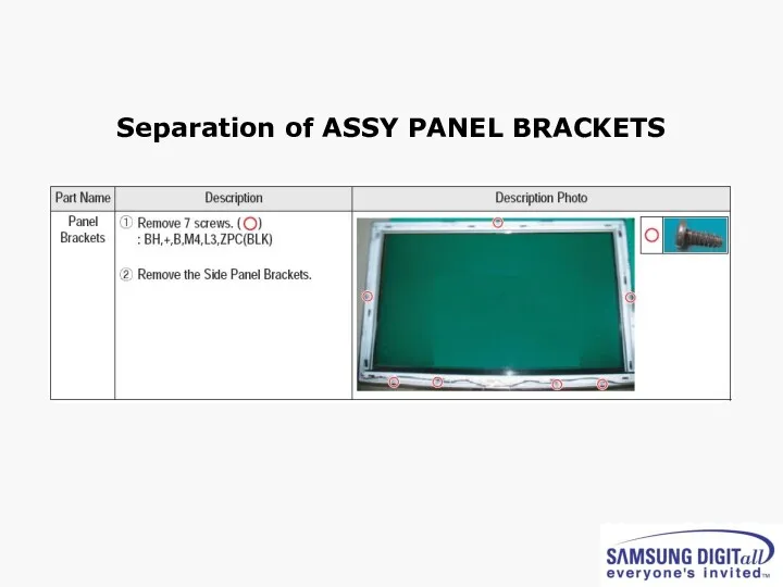
Separation of ASSY PANEL BRACKETS
Separation of ASSY PANEL BRACKETS
3. Trouble shooting
3. Trouble shooting
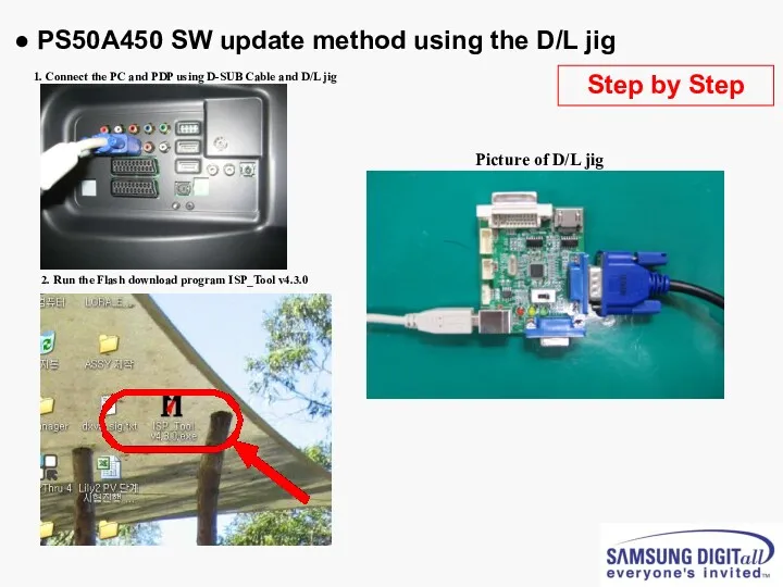
● PS50A450 SW update method using the D/L jig
D-SUB Cable
1. Connect
● PS50A450 SW update method using the D/L jig
D-SUB Cable
1. Connect
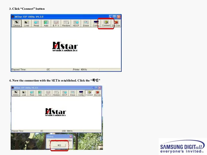
3. Click “Connect” button
4. Now the connection with the SET
3. Click “Connect” button
4. Now the connection with the SET
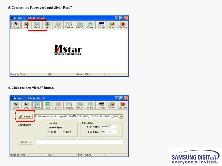
5. Connect the Power cord and click “Read”
6. Click the new
5. Connect the Power cord and click “Read”
6. Click the new
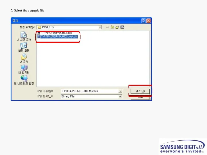
7. Select the upgrade file
7. Select the upgrade file
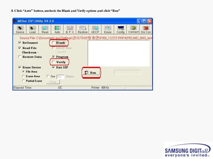
8. Click “Auto” button, uncheck the Blank and Verify options and
8. Click “Auto” button, uncheck the Blank and Verify options and
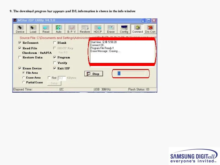
9. The download progress bar appears and D/L information is shown
9. The download progress bar appears and D/L information is shown
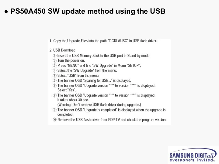
● PS50A450 SW update method using the USB
● PS50A450 SW update method using the USB
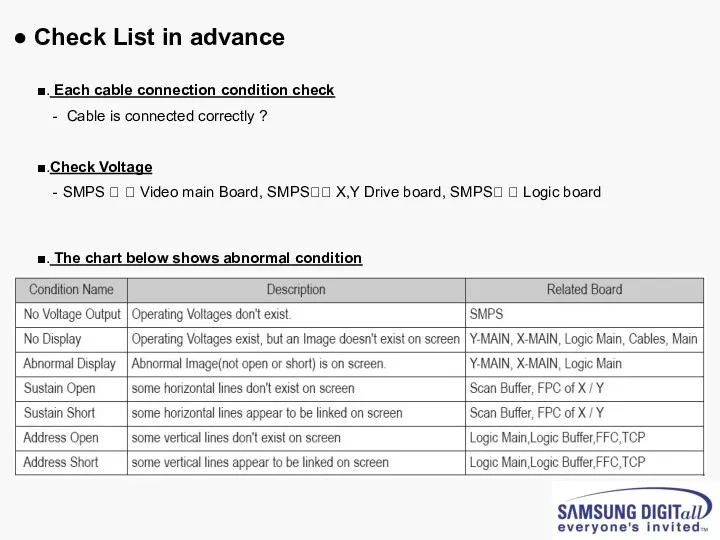
● Check List in advance
■. Each cable connection condition check
● Check List in advance
■. Each cable connection condition check
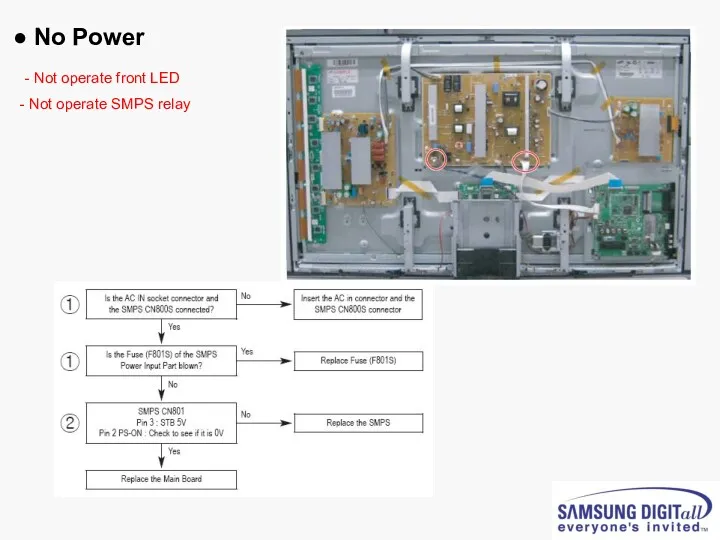
● No Power
- Not operate front LED
Not operate SMPS relay
● No Power
- Not operate front LED
Not operate SMPS relay
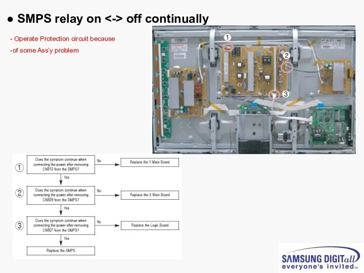
● SMPS relay on <-> off continually
Operate Protection circuit
● SMPS relay on <-> off continually
Operate Protection circuit
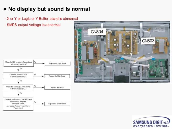
● No display but sound is normal
X or Y
● No display but sound is normal
X or Y
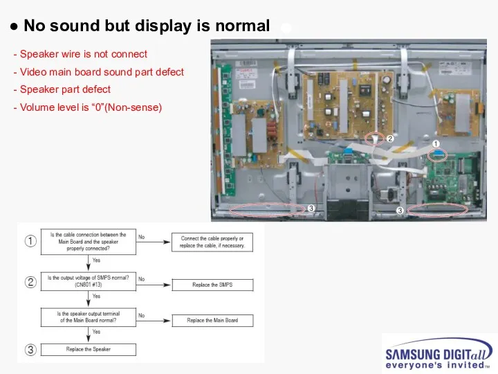
● No sound but display is normal
Speaker wire is
● No sound but display is normal
Speaker wire is
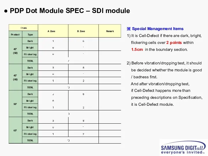
● PDP Dot Module SPEC – SDI module
※ Special Management Items
1)
● PDP Dot Module SPEC – SDI module
※ Special Management Items
1)
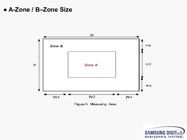
● A-Zone / B–Zone Size
● A-Zone / B–Zone Size
PC timming
PC timming
3D Function
3D Function
 к уроку технологии
 Праздник профессий
 Поделки из природного материала и овощей
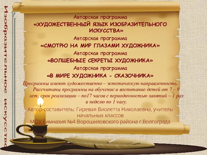 Дополнительные авторские программы художественно - эстетической направленности: ХУДОЖЕСТВЕННЫЙ ЯЗЫК ИЗОБРАЗИТЕЛЬНОГО ИСКУССТВА, СМОТРЮ НА МИР ГЛАЗАМИ ХУДОЖНИКА, ВОЛШЕБНЫЕ СЕКРЕТЫ ХУДОЖНИКА, В МИРЕ ХУДОЖ
 экскурсия на хлебозавод г. Нижний Новгород
 Специальные предложения для хозяйки
 Ленинград - город герой ( презентация)
 Страны Восточной Европы
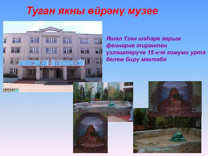 “ Туган якны өйрәнү” музее.
 Число π. История длиною в 4000 лет
 Этот волшебный Новый Год.
 Компания ALStyle Россия
 национальный состав населения
 Технологическая цепочка. География чёрной металлургии
 Марк Твен (Сэмюэл Лэнгхорн Клеменс)
 Профилактика и коррекция оптической дисграфии у учащихся начальной школы на уроках русского языка
 Формирование художественно-эстетических эталонов при реализации образовательной области Художественное творчество
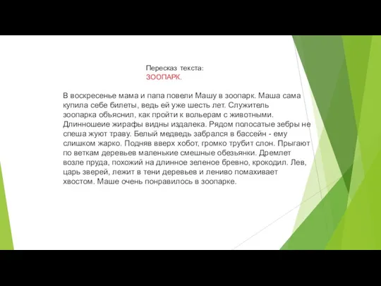 Пересказ рассказа Зоопарк
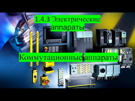 Электрические аппараты. Коммутационные аппараты. Тема 1.4.3
 Гигиена полости рта, ее роль в профилактике стоматологических заболеваний у детей. (Лекция 11)
 Экоурок Сделаем вместе. Лес - наше богатство. Сохраним его для потомков
 Джек Лондон. Роман Маленькая хозяйка большого дома
 Урок 3. Upd
 Страны АСЕАН. Анимированный трафарет
 TYPES_OF_COMPUTERS
 Составные элементы ПК TEMPEST (ROXAR)
 Особенности преподавания математики...ТОНК, ч.1
 Planeta_Merkurii_774_-1 (1)