- Removing 6634 UEPP

Содержание
- 2. Remove the LCD monitor harnesses 4. Disconnect the harnesses, you may leave the video cable connected
- 3. Remove the LCD Monitor 5. Remove shipping screws, if they are still present. 6. To disengage
- 4. Note the monitor is mounted by two plungers, one on each side. Plunger
- 5. Remove the Touch Screen Latches Press down on each latch 7. Press down on each latch
- 6. Finish Removing the Touch Screen 8. From the front of the ATM remove the retaining wire
- 7. Remove the shutters 9. Disconnect the USB and power harnesses from the shutters 10. Remove the
- 8. Front view of a shutter Stud Screws
- 9. Remove the keyboard support plate Note: The picture was taken with the dispenser shutter still in
- 10. Viewed from the front of the ATM 14. Reverse order, for assembly of components Keyboard Support
- 12. Скачать презентацию
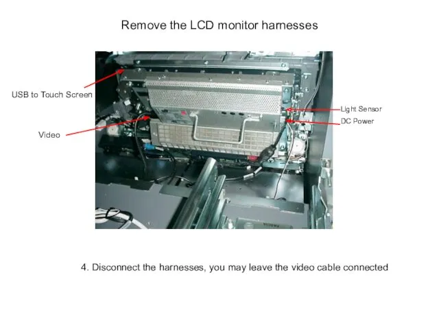
Remove the LCD monitor harnesses
4. Disconnect the harnesses, you may leave
Remove the LCD monitor harnesses
4. Disconnect the harnesses, you may leave
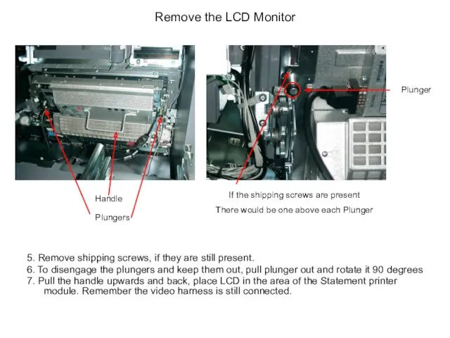
Remove the LCD Monitor
5. Remove shipping screws, if they are still
Remove the LCD Monitor
5. Remove shipping screws, if they are still
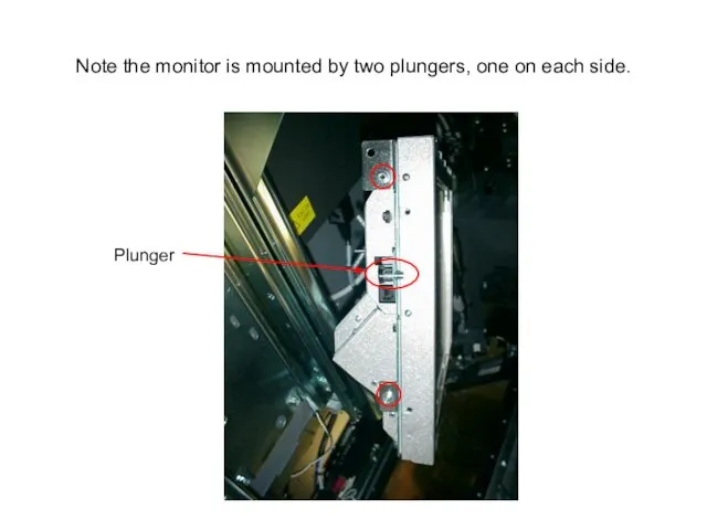
Note the monitor is mounted by two plungers, one on each
Note the monitor is mounted by two plungers, one on each
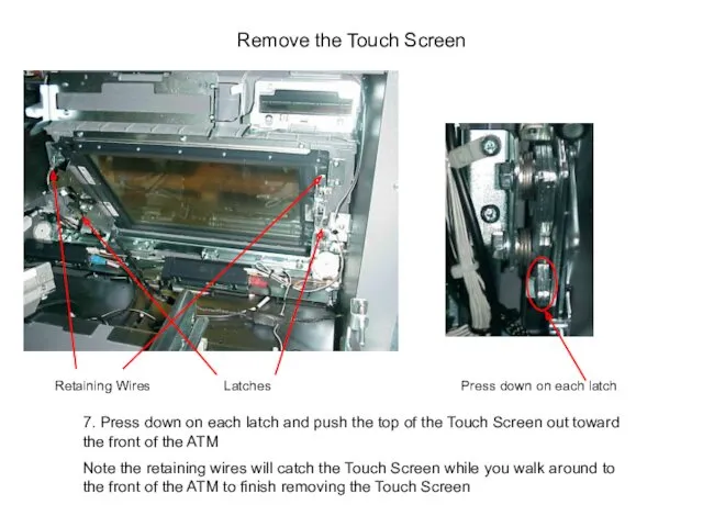
Remove the Touch Screen
Latches
Press down on each latch
7. Press down on
Remove the Touch Screen
Latches
Press down on each latch
7. Press down on
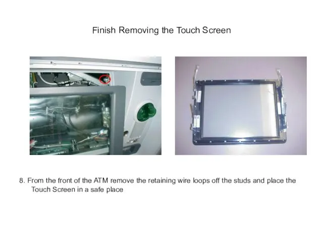
Finish Removing the Touch Screen
8. From the front of the ATM
Finish Removing the Touch Screen
8. From the front of the ATM
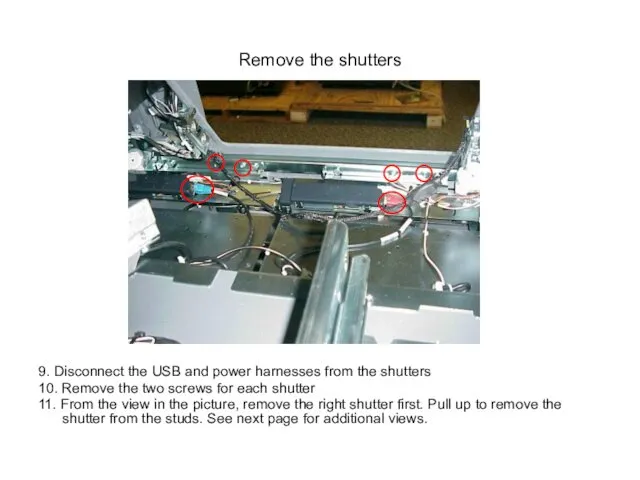
Remove the shutters
9. Disconnect the USB and power harnesses from the
Remove the shutters
9. Disconnect the USB and power harnesses from the
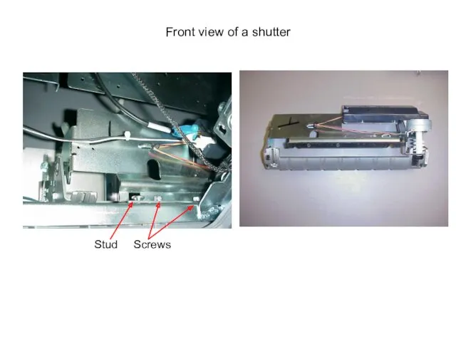
Front view of a shutter
Stud Screws
Front view of a shutter
Stud Screws
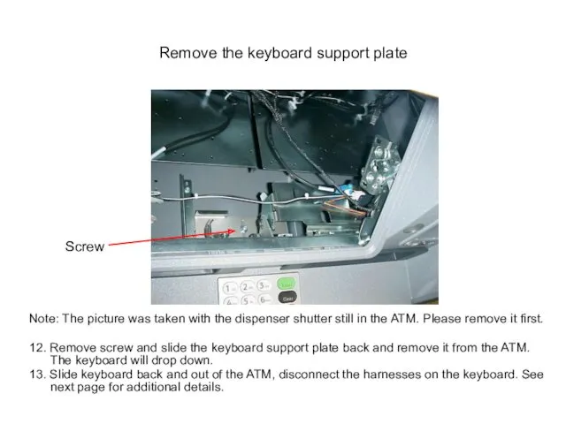
Remove the keyboard support plate
Note: The picture was taken with the
Remove the keyboard support plate
Note: The picture was taken with the
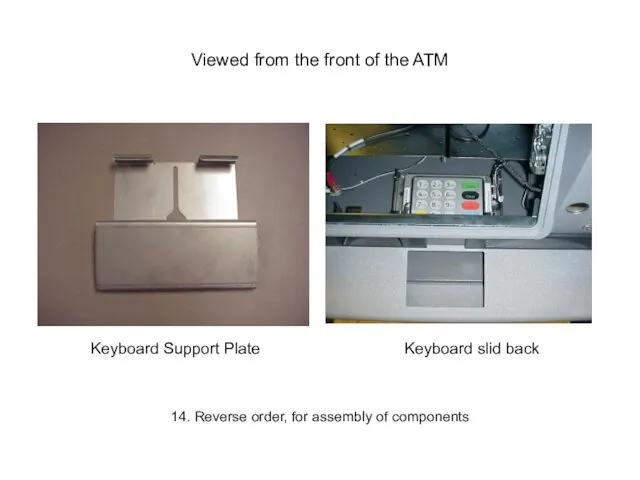
Viewed from the front of the ATM
14. Reverse order, for assembly
Viewed from the front of the ATM
14. Reverse order, for assembly
 Игрушки к Новому Году для детей и родителей
 Шаблон Фракталы-23
 Основание греческих колоний
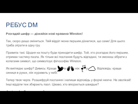 РЕБУС DМ. Розгадай шифр — дізнайся нові правила Winston
 Химическая связь
 Атенюатори і вимірювання послаблень. Прилади для вимірювання послаблень. (Тема 16.1)
 Уровни структуры методологического знания. Примеры научного знания каждого уровня
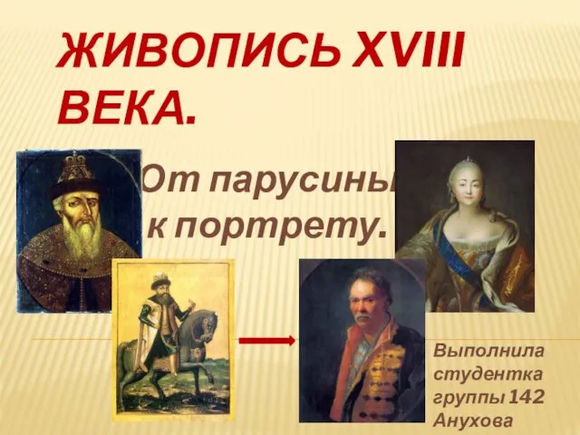 Живопись XVIII века
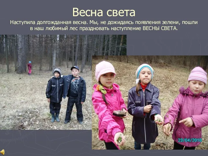 Для Вас, выпускники: весна 2 класс
 Мифическое время правремя, начальное, раннее, первое, предшествующее эмпирическому (профанному) времени
 Туристские формальности стран Скандинавии
 Классификация и определения механизмов. (Лекция 1)
 Своя игра на тему Здоровый образ жизни
 Дизайн. Тренды в графическом дизайне 2017
 Новогодняя открытка 2019
 Сретение Господне
 Презентация Домашние птицы.
 Конструктивные решения по усилению строительных конструкций
 ВозможностиЕ-КМ школы
 Методика сортоизучения древесных растений
 Зонная теория твердого тела
 Время реакции человека
 Программа коррекционно-развивающей работы с детьми с задержкой психического развития
 Психологические особенности периода взрослости
 Театрализованная игра как средство развития интонационной выразительности речи детей старшего дошкольного возраста
 Физико-химические свойства пластовых флюидов. Условия притока жидкостей и газов. (Лекция 2)
 Русская архитектура первой половины 19 века
 Оборудование кондитерского цеха