- SVC Mode Menus. How to use the Adjustment Remote Controller

Содержание
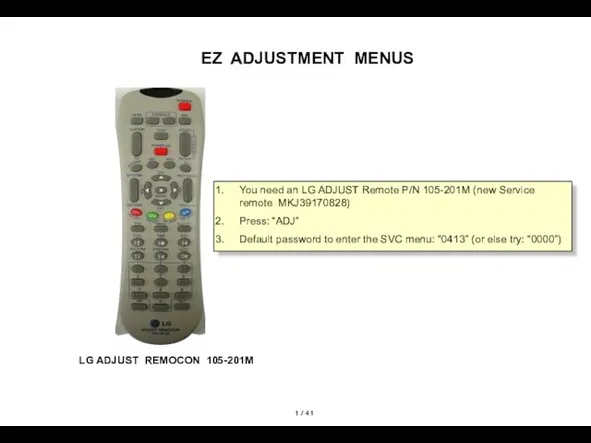
- 2. / 41 EZ ADJUSTMENT MENUS LG ADJUST REMOCON 105-201M You need an LG ADJUST Remote P/N
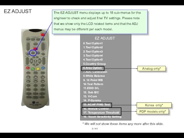
- 3. / 41 EZ ADJUST Korea only* Analog only* The EZ-ADJUST menu displays up to 18 sub-menus
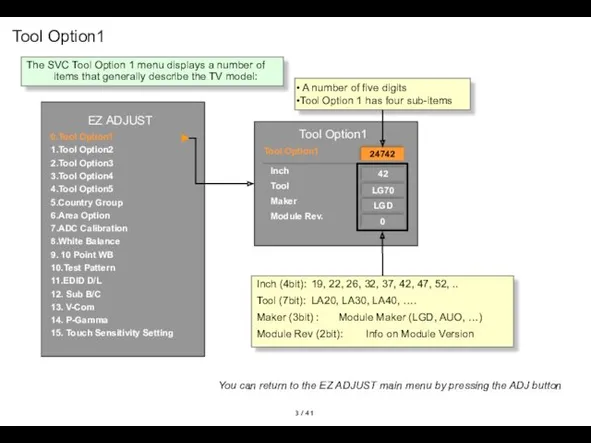
- 4. / 41 Tool Option1 A number of five digits Tool Option 1 has four sub-items Inch
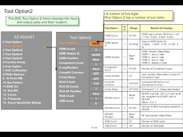
- 5. / 41 Tool Option2 Tool Option2 54695 3 NONE 1 HDMI Count HDMI Switch IC HDMI
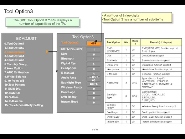
- 6. / 41 Tool Option3 Tool Option3 493 1 0 1 0 EMF(JPEG,MP3) Divx Bluetooth Digital Eye
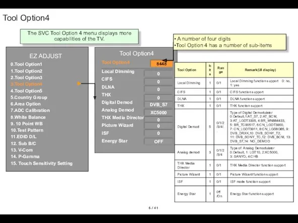
- 7. / 41 Tool Option4 Tool Option4 Tool Option4 EZ ADJUST 8448 0 0 DVB_S7 XC5000 Local
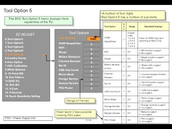
- 8. / 41 Tool Option 5 Tool Option4 Tool Option 5 EZ ADJUST 8448 0 0 0
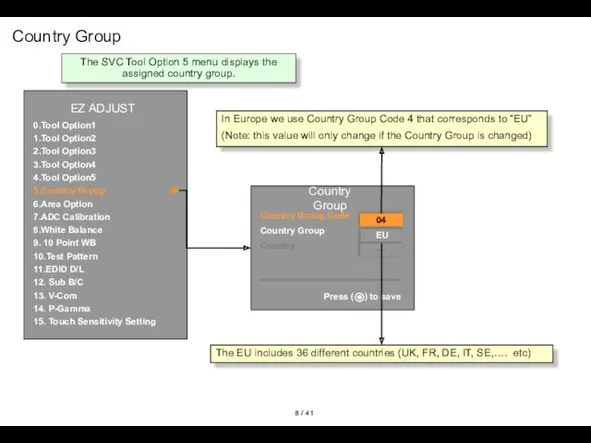
- 9. / 41 Country Group EZ ADJUST EZ ADJUST EZ ADJUST 0.Tool Option1 1.Tool Option2 2.Tool Option3
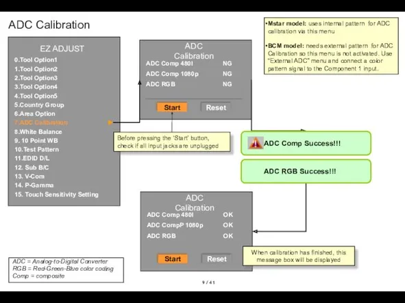
- 10. / 41 ADC Calibration ADC Comp Success!!! ADC RGB Success!!! EZ ADJUST EZ ADJUST EZ ADJUST
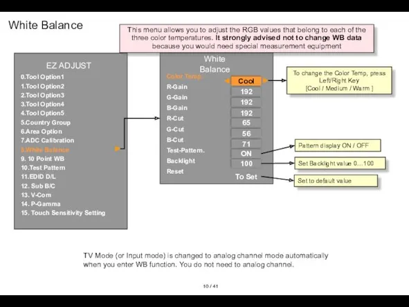
- 11. / 41 White Balance Color Temp. R-Gain G-Gain B-Gain R-Cut G-Cut B-Cut Test-Pattern. Backlight Reset Cool
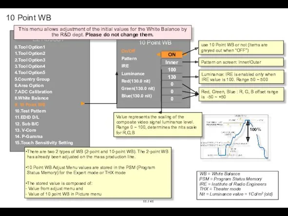
- 12. / 41 10 Point WB 10 Point WB On/Off Pattern IRE Luminance Red(130.0 nit) Green(130.0 nit)
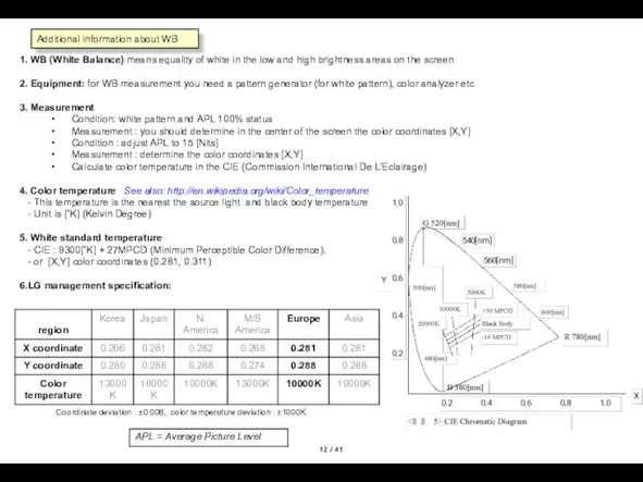
- 13. / 41 1. WB (White Balance) means equality of white in the low and high brightness
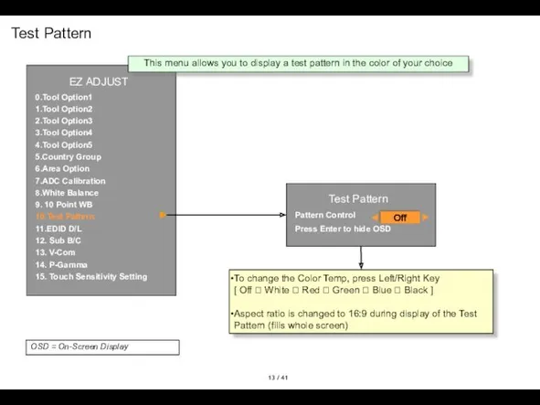
- 14. / 41 Test Pattern Test Pattern Pattern Control Press Enter to hide OSD Off To change
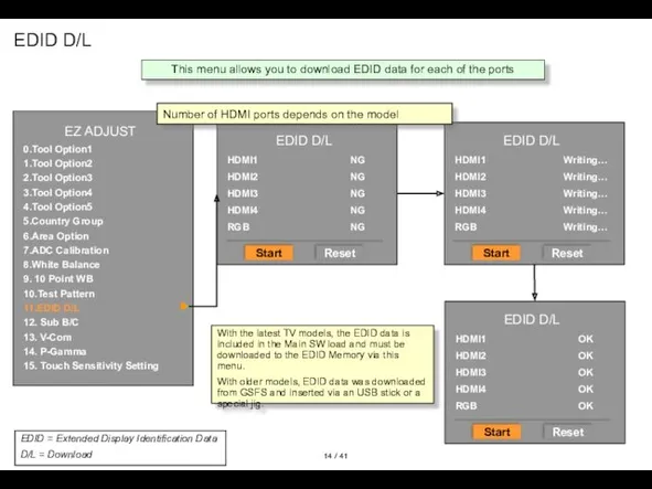
- 15. / 41 EDID D/L EZ ADJUST EZ ADJUST 0.Tool Option1 1.Tool Option2 2.Tool Option3 3.Tool Option4
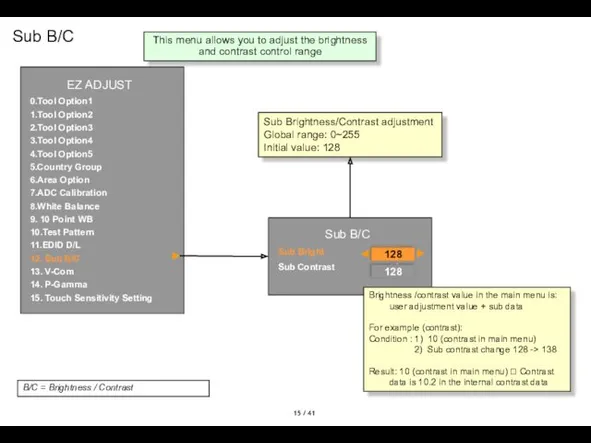
- 16. / 41 Sub B/C Sub Brightness/Contrast adjustment Global range: 0~255 Initial value: 128 EZ ADJUST EZ
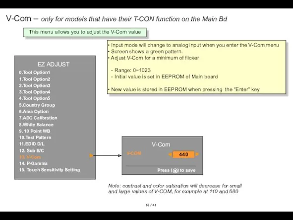
- 17. / 41 V-Com – only for models that have their T-CON function on the Main Bd
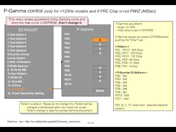
- 18. / 41 P-Gamma control (only for >120Hz models and if FRC Chip is not PWIZ (MStar))
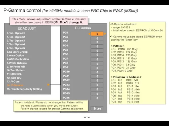
- 19. / 41 P-Gamma control (for >240Hz models in case FRC Chip is PWIZ (MStar)) P-Gamma adjustment
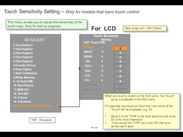
- 20. / 41 Touch Sensitivity Setting – Only for models that have touch control EZ ADJUST EZ
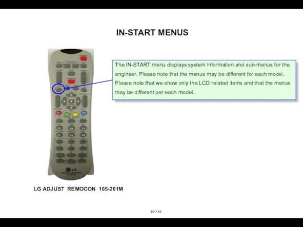
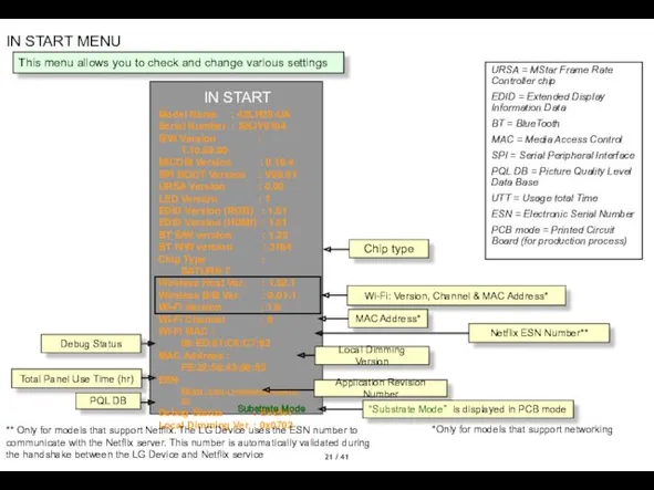
- 21. / 41 IN-START MENUS LG ADJUST REMOCON 105-201M The IN-START menu displays system information and sub-menus
- 22. / 41 IN START MENU IN START Model Name : 42LH7000-ZA S/W Version : V01.10.00 MICOM
- 23. / 41 IN START MENU IN START IN START Model Name : 42LH7000-ZA S/W Version :
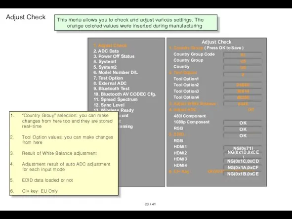
- 24. / 41 Adjust Check Adjust Check 1. Country Group ( Press OK to Save ) Country
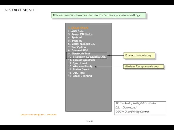
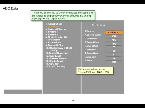
- 25. / 41 ADC Data 1. Adjust Check 2. ADC Data 3. Power Off Status 4. System
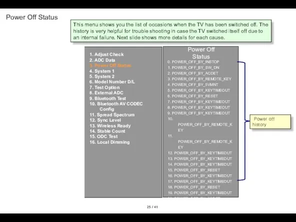
- 26. / 41 Power Off Status Power Off Status 0. POWER_OFF_BY_INSTOP 1. POWER_OFF_BY_SW_DN 2. POWER_OFF_BY_ACDET 3. POWER_OFF_BY_REMOTE_KEY
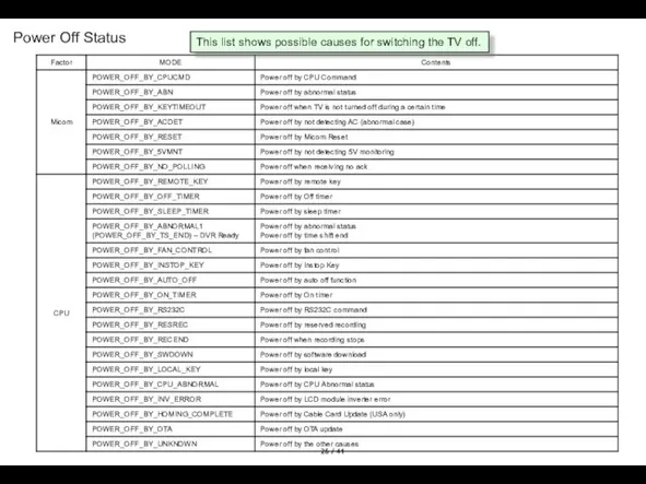
- 27. / 41 Power Off Status This list shows possible causes for switching the TV off.
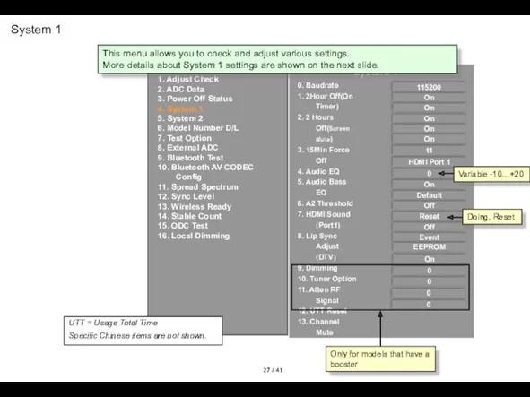
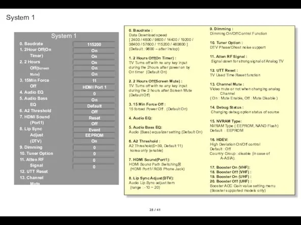
- 28. / 41 System 1 System 1 0. Baudrate 1. 2Hour Off(On Timer) 2. 2 Hours Off(Screen
- 29. / 41 System 1 0. Baudrate 1. 2Hour Off(On Timer) 2. 2 Hours Off(Screen Mute) 3.
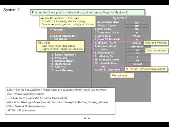
- 30. / 41 System 2 System 2 0. Screen Saver Cube 1. RS-232C Control 2. SSID Control
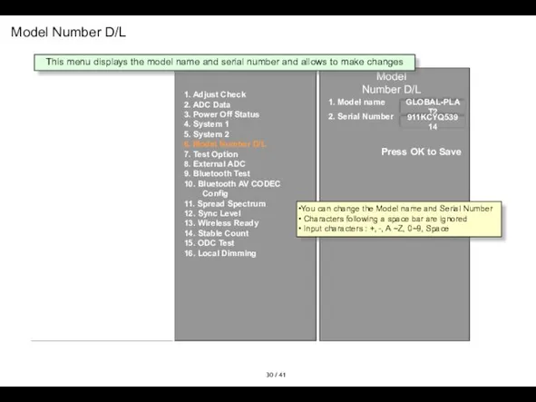
- 31. / 41 Model Number D/L Model Number D/L 1. Model name 2. Serial Number GLOBAL-PLAT2 911KCYQ53914
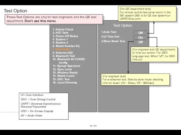
- 32. / 41 Test Option Test Option 1.Auto Test 2.UI Time Out 3.Store Mode Test Off On
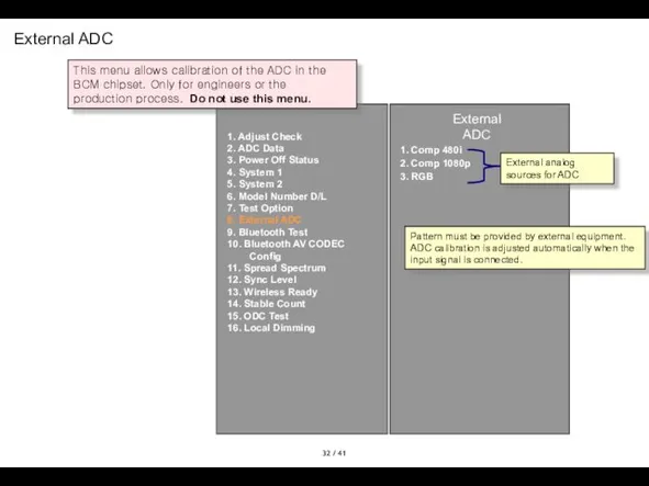
- 33. / 41 External ADC External ADC 1. Comp 480i 2. Comp 1080p 3. RGB External analog
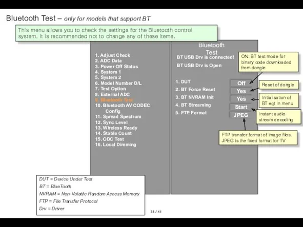
- 34. / 41 Bluetooth Test – only for models that support BT 1. Adjust Check 2. ADC
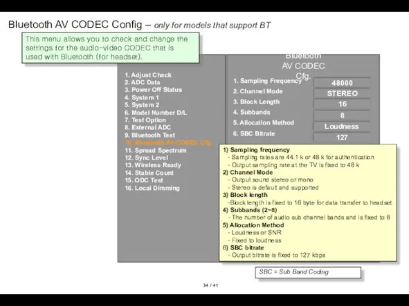
- 35. / 41 Bluetooth AV CODEC Config – only for models that support BT 1. Adjust Check
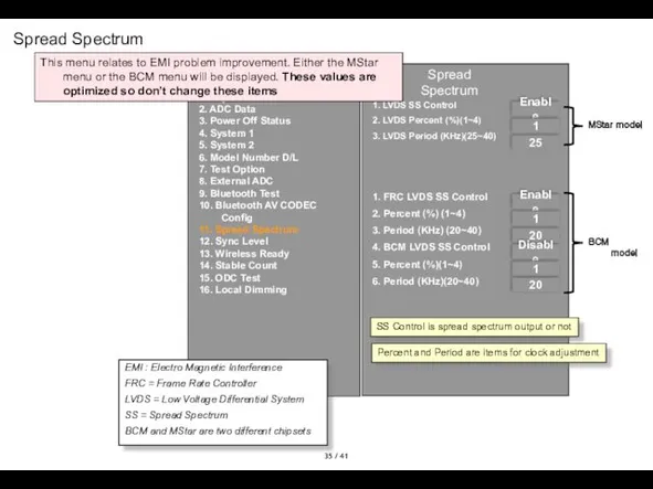
- 36. / 41 Spread Spectrum Spread Spectrum 1. LVDS SS Control 2. LVDS Percent (%)(1~4) 3. LVDS
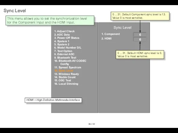
- 37. / 41 Sync Level Sync Level 1. Component 2. HDMI 6 6 1. Adjust Check 2.
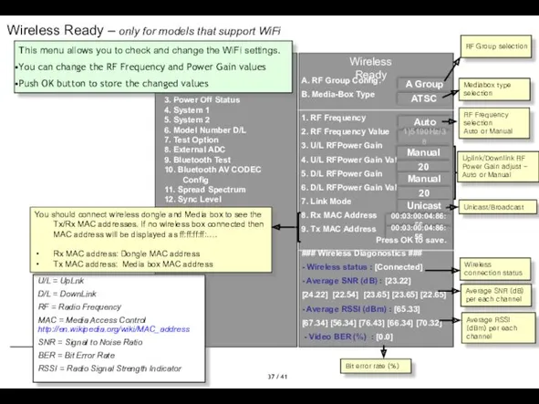
- 38. / 41 A. RF Group Config. B. Media-Box Type 1. RF Frequency 2. RF Frequency Value
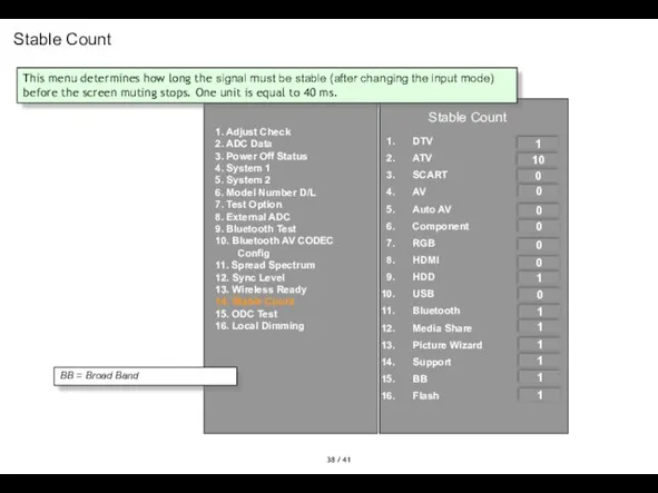
- 39. / 41 Stable Count Stable Count DTV ATV SCART AV Auto AV Component RGB HDMI HDD
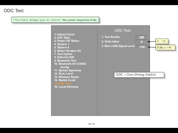
- 40. / 41 ODC Test ODC Test 1. Test Enable 2. Table Index 3. Mini LVDS Signal
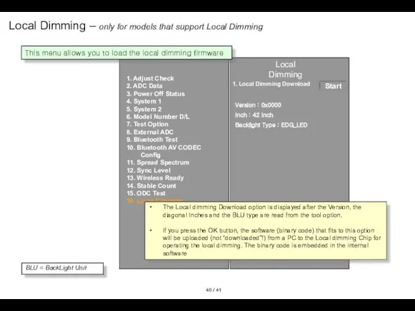
- 41. / 41 Local Dimming – only for models that support Local Dimming Local Dimming 1. Local
- 43. Скачать презентацию
/ 41
EZ ADJUSTMENT MENUS
LG ADJUST REMOCON 105-201M
You need an LG
/ 41
EZ ADJUSTMENT MENUS
LG ADJUST REMOCON 105-201M
You need an LG
/ 41
EZ ADJUST
Korea only*
Analog only*
The EZ-ADJUST menu displays up to
/ 41
EZ ADJUST
Korea only*
Analog only*
The EZ-ADJUST menu displays up to
/ 41
Tool Option1
A number of five digits
Tool Option 1
/ 41
Tool Option1
A number of five digits
Tool Option 1
/ 41
Tool Option2
Tool Option2
54695
3
NONE
1
HDMI Count
HDMI Switch IC
HDMI Position
Component Count
CompPosition
CompAV Common
Comp
/ 41
Tool Option2
Tool Option2
54695
3
NONE
1
HDMI Count
HDMI Switch IC
HDMI Position
Component Count
CompPosition
CompAV Common
Comp
/ 41
Tool Option3
Tool Option3
493
1
0
1
0
EMF(JPEG,MP3)
Divx
Bluetooth
Digital Eye
Headphone
E-Manual
Audio Amp
Backlight Type
Wireless Ready
Boot Logo
DVR Ready
Instant
/ 41
Tool Option3
Tool Option3
493
1
0
1
0
EMF(JPEG,MP3)
Divx
Bluetooth
Digital Eye
Headphone
E-Manual
Audio Amp
Backlight Type
Wireless Ready
Boot Logo
DVR Ready
Instant
/ 41
Tool Option4
Tool Option4
Tool Option4
EZ ADJUST
8448
0
0
DVB_S7
XC5000
Local Dimming
CIFS
DLNA
THX
Digital Demod
Analog Demod
THX Media
/ 41
Tool Option4
Tool Option4
Tool Option4
EZ ADJUST
8448
0
0
DVB_S7
XC5000
Local Dimming
CIFS
DLNA
THX
Digital Demod
Analog Demod
THX Media
/ 41
Tool Option 5
Tool Option4
Tool Option 5
EZ ADJUST
8448
0
0
0
1
HDMI Swap/Order
WiFi
Skype
Motion Remocon
Channel
/ 41
Tool Option 5
Tool Option4
Tool Option 5
EZ ADJUST
8448
0
0
0
1
HDMI Swap/Order
WiFi
Skype
Motion Remocon
Channel
/ 41
Country Group
EZ ADJUST
EZ ADJUST
EZ ADJUST
0.Tool Option1
1.Tool Option2
2.Tool Option3
3.Tool Option4
4.Tool
/ 41
Country Group
EZ ADJUST
EZ ADJUST
EZ ADJUST
0.Tool Option1
1.Tool Option2
2.Tool Option3
3.Tool Option4
4.Tool
/ 41
ADC Calibration
ADC Comp Success!!!
ADC RGB Success!!!
EZ ADJUST
EZ
/ 41
ADC Calibration
ADC Comp Success!!!
ADC RGB Success!!!
EZ ADJUST
EZ
/ 41
White Balance
Color Temp.
R-Gain
G-Gain
B-Gain
R-Cut
G-Cut
B-Cut
Test-Pattern.
Backlight
Reset
Cool
192
192
192
65
56
71
100
To Set
ON
White Balance
To change the Color Temp,
/ 41
White Balance
Color Temp.
R-Gain
G-Gain
B-Gain
R-Cut
G-Cut
B-Cut
Test-Pattern.
Backlight
Reset
Cool
192
192
192
65
56
71
100
To Set
ON
White Balance
To change the Color Temp,
/ 41
10 Point WB
10 Point WB
On/Off
Pattern
IRE
Luminance
Red(130.0 nit)
Green(130.0 nit)
Blue(130.0 nit)
ON
Inner
100
130
0
0
0
EZ ADJUST
0.Tool
/ 41
10 Point WB
10 Point WB
On/Off
Pattern
IRE
Luminance
Red(130.0 nit)
Green(130.0 nit)
Blue(130.0 nit)
ON
Inner
100
130
0
0
0
EZ ADJUST
0.Tool
/ 41
1. WB (White Balance) means equality of white in
/ 41
1. WB (White Balance) means equality of white in
/ 41
Test Pattern
Test Pattern
Pattern Control
Press Enter to hide OSD
Off
To change
/ 41
Test Pattern
Test Pattern
Pattern Control
Press Enter to hide OSD
Off
To change
/ 41
EDID D/L
EZ ADJUST
EZ ADJUST
0.Tool Option1
1.Tool Option2
2.Tool Option3
3.Tool Option4
4.Tool Option5
5.Country
/ 41
EDID D/L
EZ ADJUST
EZ ADJUST
0.Tool Option1
1.Tool Option2
2.Tool Option3
3.Tool Option4
4.Tool Option5
5.Country
/ 41
Sub B/C
Sub Brightness/Contrast adjustment
Global range: 0~255
Initial value: 128
EZ ADJUST
EZ
/ 41
Sub B/C
Sub Brightness/Contrast adjustment
Global range: 0~255
Initial value: 128
EZ ADJUST
EZ
/ 41
V-Com – only for models that have their T-CON
/ 41
V-Com – only for models that have their T-CON
/ 41
P-Gamma control (only for >120Hz models and if FRC
/ 41
P-Gamma control (only for >120Hz models and if FRC
/ 41
P-Gamma control (for >240Hz models in case FRC Chip
/ 41
P-Gamma control (for >240Hz models in case FRC Chip
/ 41
Touch Sensitivity Setting – Only for models that have
/ 41
Touch Sensitivity Setting – Only for models that have
/ 41
IN-START MENUS
LG ADJUST REMOCON 105-201M
The IN-START menu displays system
/ 41
IN-START MENUS
LG ADJUST REMOCON 105-201M
The IN-START menu displays system
/ 41
IN START MENU
IN START
Model Name : 42LH7000-ZA
S/W Version :
/ 41
IN START MENU
IN START
Model Name : 42LH7000-ZA
S/W Version :
/ 41
IN START MENU
IN START
IN START
Model Name : 42LH7000-ZA
S/W Version
/ 41
IN START MENU
IN START
IN START
Model Name : 42LH7000-ZA
S/W Version
/ 41
Adjust Check
Adjust Check
1. Country Group ( Press OK to
/ 41
Adjust Check
Adjust Check
1. Country Group ( Press OK to
/ 41
ADC Data
1. Adjust Check
2. ADC Data
3. Power Off Status
4.
/ 41
ADC Data
1. Adjust Check
2. ADC Data
3. Power Off Status
4.
/ 41
Power Off Status
Power Off Status
0. POWER_OFF_BY_INSTOP
1. POWER_OFF_BY_SW_DN
2. POWER_OFF_BY_ACDET
3. POWER_OFF_BY_REMOTE_KEY
4.
/ 41
Power Off Status
Power Off Status
0. POWER_OFF_BY_INSTOP
1. POWER_OFF_BY_SW_DN
2. POWER_OFF_BY_ACDET
3. POWER_OFF_BY_REMOTE_KEY
4.
/ 41
Power Off Status
This list shows possible causes for switching
/ 41
Power Off Status
This list shows possible causes for switching
/ 41
System 1
System 1
0. Baudrate
1. 2Hour Off(On Timer)
2. 2 Hours
/ 41
System 1
System 1
0. Baudrate
1. 2Hour Off(On Timer)
2. 2 Hours
/ 41
System 1
0. Baudrate
1. 2Hour Off(On Timer)
2. 2 Hours Off(Screen
/ 41
System 1
0. Baudrate
1. 2Hour Off(On Timer)
2. 2 Hours Off(Screen
/ 41
System 2
System 2
0. Screen Saver Cube
1. RS-232C Control
2. SSID
/ 41
System 2
System 2
0. Screen Saver Cube
1. RS-232C Control
2. SSID
/ 41
Model Number D/L
Model Number D/L
1. Model name
2. Serial Number
GLOBAL-PLAT2
911KCYQ53914
1.
/ 41
Model Number D/L
Model Number D/L
1. Model name
2. Serial Number
GLOBAL-PLAT2
911KCYQ53914
1.
/ 41
Test Option
Test Option
1.Auto Test
2.UI Time Out
3.Store Mode Test
Off
On
Off
(For QE
/ 41
Test Option
Test Option
1.Auto Test
2.UI Time Out
3.Store Mode Test
Off
On
Off
(For QE
/ 41
External ADC
External ADC
1. Comp 480i
2. Comp 1080p
3. RGB
External analog
/ 41
External ADC
External ADC
1. Comp 480i
2. Comp 1080p
3. RGB
External analog
/ 41
Bluetooth Test – only for models that support BT
1.
/ 41
Bluetooth Test – only for models that support BT
1.
/ 41
Bluetooth AV CODEC Config – only for models that
/ 41
Bluetooth AV CODEC Config – only for models that
/ 41
Spread Spectrum
Spread Spectrum
1. LVDS SS Control
2. LVDS Percent (%)(1~4)
3.
/ 41
Spread Spectrum
Spread Spectrum
1. LVDS SS Control
2. LVDS Percent (%)(1~4)
3.
/ 41
Sync Level
Sync Level
1. Component
2. HDMI
6
6
1. Adjust Check
2. ADC Data
3.
/ 41
Sync Level
Sync Level
1. Component
2. HDMI
6
6
1. Adjust Check
2. ADC Data
3.
/ 41
A. RF Group Config.
B. Media-Box Type
1. RF Frequency
2. RF
/ 41
A. RF Group Config.
B. Media-Box Type
1. RF Frequency
2. RF
/ 41
Stable Count
Stable Count
DTV
ATV
SCART
AV
Auto AV
Component
RGB
HDMI
HDD
USB
Bluetooth
Media Share
Picture Wizard
Support
BB
Flash
1
10
0
0
0
0
0
0
1
0
1
1
1
1
1
1
1. Adjust Check
2. ADC
/ 41
Stable Count
Stable Count
DTV
ATV
SCART
AV
Auto AV
Component
RGB
HDMI
HDD
USB
Bluetooth
Media Share
Picture Wizard
Support
BB
Flash
1
10
0
0
0
0
0
0
1
0
1
1
1
1
1
1
1. Adjust Check
2. ADC
/ 41
ODC Test
ODC Test
1. Test Enable
2. Table Index
3. Mini LVDS
/ 41
ODC Test
ODC Test
1. Test Enable
2. Table Index
3. Mini LVDS
/ 41
Local Dimming – only for models that support Local
/ 41
Local Dimming – only for models that support Local
 Православное христианство
 Стихотворение С. Маршака Хороший день
 Презентация по теме Экспериментирование со звуком
 Презентация к уроку на тему: Плоские поверхности и плоскости Диск
 кислотные дожди
 Airport of our dreams
 Викторина по физике Самый умный. Тепловые и электрические явления (8 класс)
 Презентация судомодельного объединения
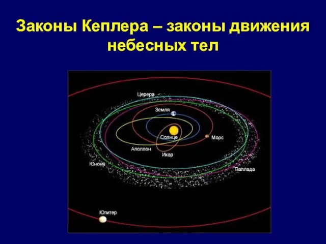 Законы Кеплера - законы движения небесных тел
 Модернизация образования: тенденции в подготовке педагогических кадров
 Презентация для урока Агротехника возделывания картофеля
 Бүйрек шаншуы
 Профилактика гриппа
 Трансформаторы силовые
 Исследование напряженно-деформированного состояния в точке тела. Лекция 6
 Начальный период евангельской истории: События, предшествующие рождеству Христа Спасителя (Лекция 3)
 Қазіргі заманғы жаңа қалып-өлшем материалдары
 Форма государства. Формы правления
 Методы исследования
 Подростковая программа от Евроазиатского института по индуктивному изучению Библии
 Сказ и загадка
 Методические рекомендации по организации выполнения и защиты, оформлению выпускной квалификационной работы
 Транспортный процесс перевозки грузов
 Профилактика ОРВИ и гриппа
 Price request Even Table
 7 чудес света
 Безопасный интернет
 Сигналы светофора