- Technical Drawing кратко

Содержание
- 2. Drawings definition Drawing ? graphic communication A drawing is a graphic representation of an object (building,
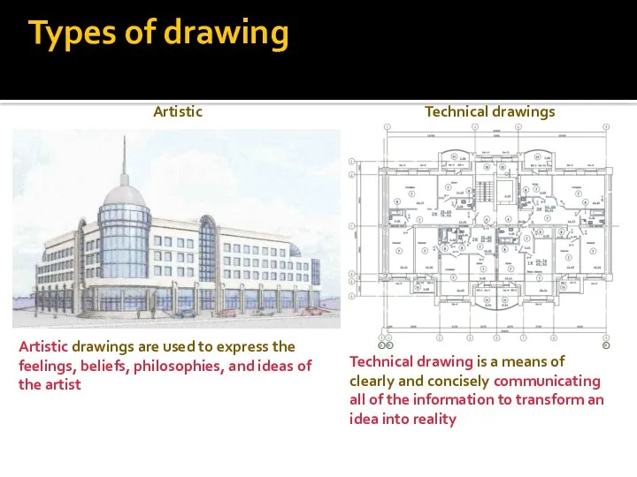
- 3. Types of drawing There are two basic types of drawings: Artistic Technical drawings Artistic drawings are
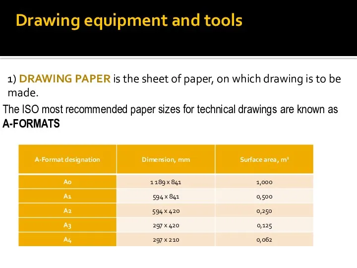
- 4. Drawing equipment and tools 1) DRAWING PAPER is the sheet of paper, on which drawing is
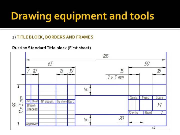
- 5. Drawing equipment and tools 2) TITLE BLOCK, BORDERS AND FRAMES Russian Standard Title block (First sheet)
- 6. Drawing equipment and tools 2) TITLE BLOCK, BORDERS AND FRAMES Russian Standard Title block (for subsequent
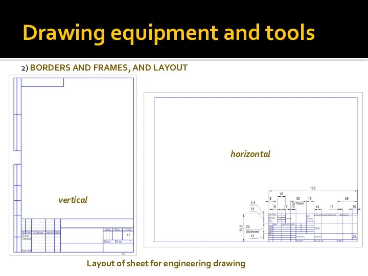
- 7. Drawing equipment and tools 2) BORDERS AND FRAMES, AND LAYOUT Layout of sheet for engineering drawing
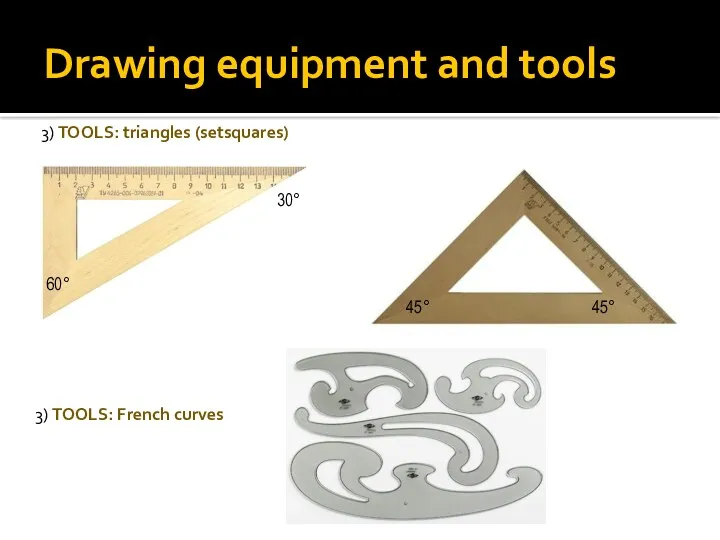
- 8. Drawing equipment and tools 3) TOOLS: triangles (setsquares) 3) TOOLS: French curves 30° 60° 45° 45°
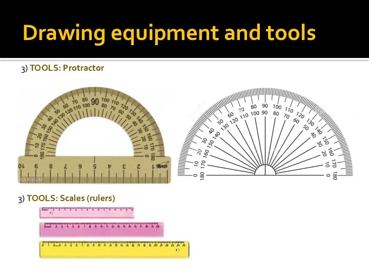
- 9. Drawing equipment and tools 3) TOOLS: Protractor 3) TOOLS: Scales (rulers)
- 10. Drawing equipment and tools 3) TOOLS: Pencil Recommended size of the lead is 8-10 mm Recommended
- 11. Drawing equipment and tools 3) TOOLS: Compass 3) TOOLS: Template
- 12. Lettering 4) LETTERING Lettering used on technical drawing written according to Russian standard 2.304-81. The height
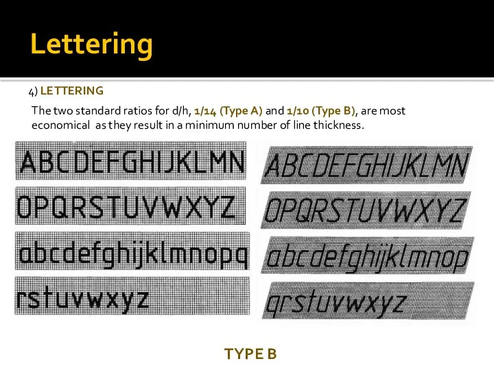
- 13. Lettering 4) LETTERING The two standard ratios for d/h, 1/14 (Type A) and 1/10 (Type B),
- 14. Lettering 4) LETTERING The two standard ratios for d/h, 1/14 (Type A) and 1/10 (Type B),
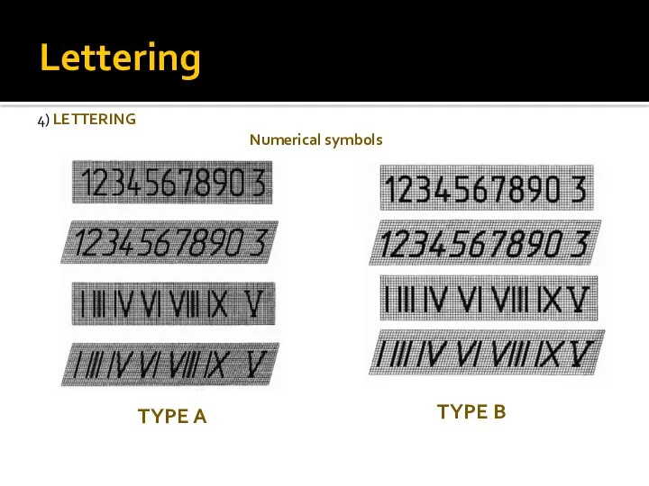
- 15. Lettering 4) LETTERING Numerical symbols TYPE B TYPE A
- 16. Types of the lines on drawings
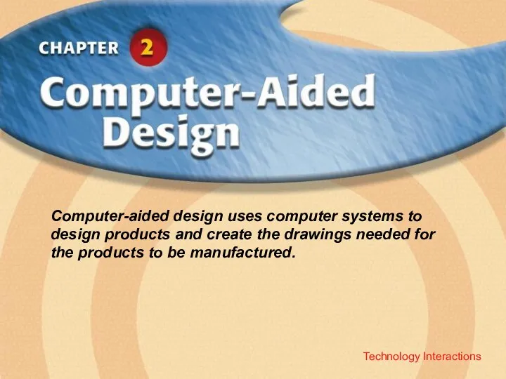
- 17. Technology Interactions Computer-aided design uses computer systems to design products and create the drawings needed for
- 18. Manual Drawing Vs CAD
- 19. What Is Computer-Aided Design? CAD is the process of designing and drafting on a computer. CAD
- 20. CAD Advantages Saves time Is more accurate Improves team communications
- 21. The CAD System Hardware Input devices, such as a keyboard and mouse Output devices, such as
- 22. Two-Dimensional (2D) CAD Can show only two dimensions of an object: Width and length Width and
- 23. Three-Dimensional (3D) CAD Wireframe models resemble “stick figures.”
- 24. Three-Dimensional (3D) CAD Surface models can look like the shape of the object.
- 25. Three-Dimensional (3D) CAD Solid models show the shape, area, and volume of an object.
- 26. Using 3D CAD Mechanical design CAD/CAM Rapid prototyping Architectural design
- 27. CAD/CAM This process combines computer-aided design and computer-aided manufacturing.
- 28. Rapid Prototyping Uses CAD data to create physical models for communicating ideas or to test designs.
- 29. Introduction to AutoCAD Engineering Drawings
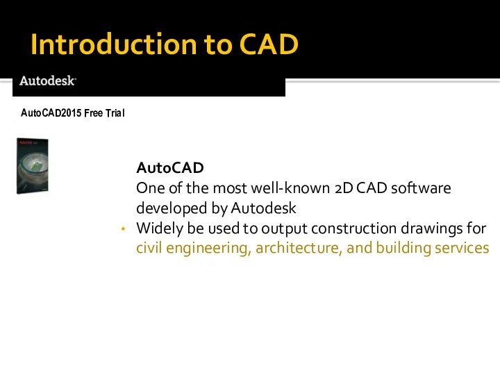
- 30. Introduction to CAD AutoCAD One of the most well-known 2D CAD software developed by Autodesk Widely
- 31. Engineering Drawing Created by AutoCAD
- 32. Architecture Drawing Created by AutoCAD
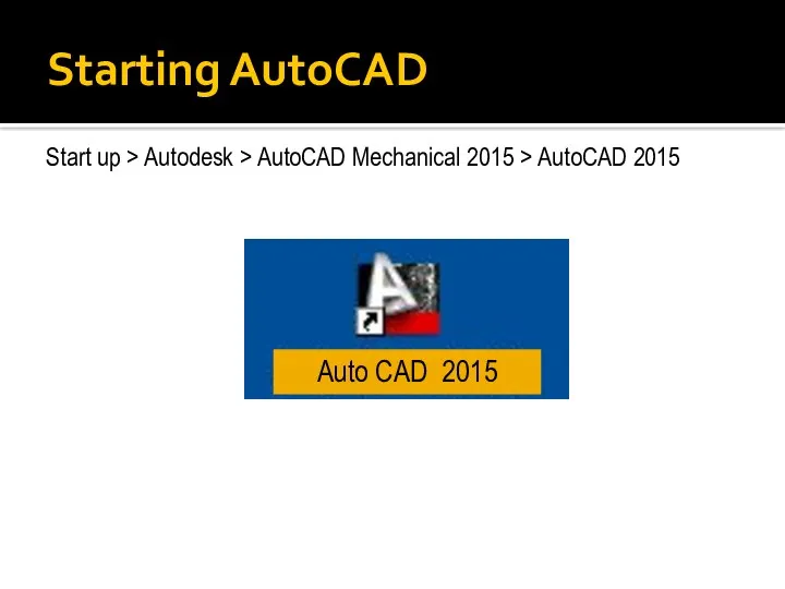
- 33. Starting AutoCAD Start up > Autodesk > AutoCAD Mechanical 2015 > AutoCAD 2015 Auto CAD 2015
- 34. User Interface (AutoCAD classic) Current File Name Menu Bar Toolbar (Icon) Layers X, y, z coordinate
- 35. AutoCAD User Interface Tabs Click here to expand panel Tooltip
- 36. AutoCAD User Interface Length Dimension Cursor Current Input Field Dynamic Prompt Angle Dimension
- 37. Mouse Interface Left button Click the specific points and select pull down menu or graphic icon
- 39. Скачать презентацию
Drawings definition
Drawing ? graphic communication
A drawing is a graphic representation of
Drawings definition
Drawing ? graphic communication
A drawing is a graphic representation of
Types of drawing
There are two basic types of drawings:
Artistic
Technical drawings
Artistic drawings
Types of drawing
There are two basic types of drawings:
Artistic
Technical drawings
Artistic drawings
Drawing equipment and tools
1) DRAWING PAPER is the sheet of paper,
Drawing equipment and tools
1) DRAWING PAPER is the sheet of paper,
Drawing equipment and tools
2) TITLE BLOCK, BORDERS AND FRAMES
Russian Standard Title
Drawing equipment and tools
2) TITLE BLOCK, BORDERS AND FRAMES
Russian Standard Title
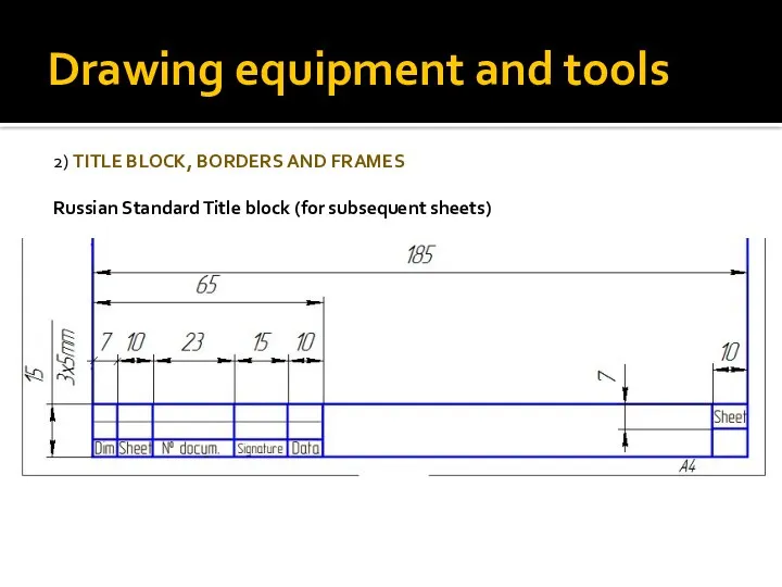
Drawing equipment and tools
2) TITLE BLOCK, BORDERS AND FRAMES
Russian Standard Title
Drawing equipment and tools
2) TITLE BLOCK, BORDERS AND FRAMES
Russian Standard Title
Drawing equipment and tools
2) BORDERS AND FRAMES, AND LAYOUT
Layout of sheet
Drawing equipment and tools
2) BORDERS AND FRAMES, AND LAYOUT
Layout of sheet
Drawing equipment and tools
3) TOOLS: triangles (setsquares)
3) TOOLS: French curves
30°
60°
45°
45°
Drawing equipment and tools
3) TOOLS: triangles (setsquares)
3) TOOLS: French curves
30°
60°
45°
45°
Drawing equipment and tools
3) TOOLS: Protractor
3) TOOLS: Scales (rulers)
Drawing equipment and tools
3) TOOLS: Protractor
3) TOOLS: Scales (rulers)
Drawing equipment and tools
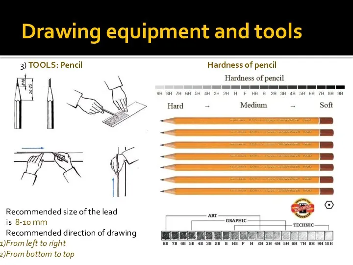
3) TOOLS: Pencil
Recommended size of the lead
is 8-10
Drawing equipment and tools
3) TOOLS: Pencil
Recommended size of the lead
is 8-10
Drawing equipment and tools
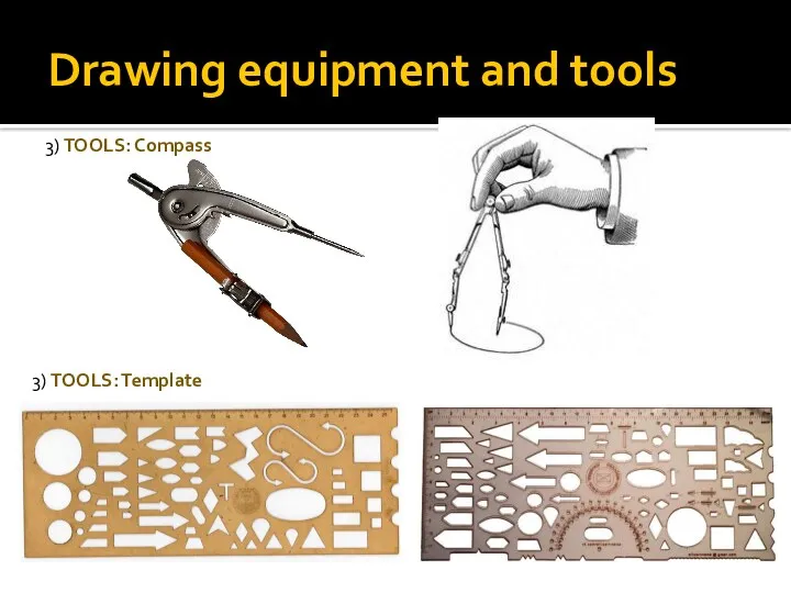
3) TOOLS: Compass
3) TOOLS: Template
Drawing equipment and tools
3) TOOLS: Compass
3) TOOLS: Template
Lettering
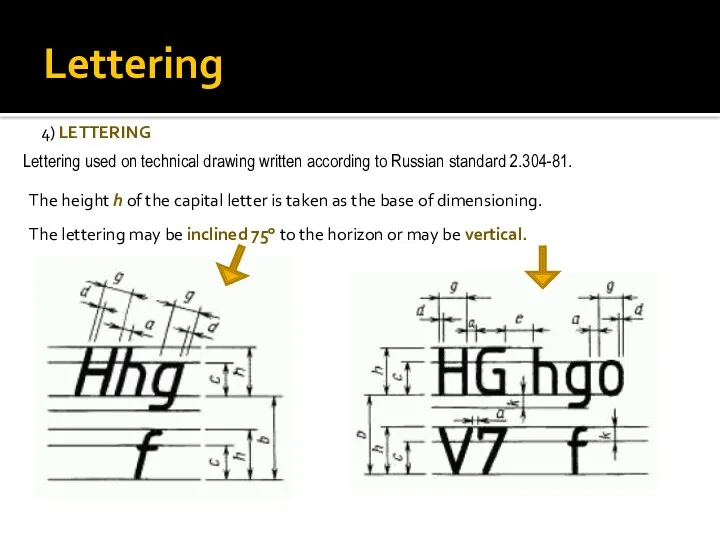
4) LETTERING
Lettering used on technical drawing written according to Russian standard
Lettering
4) LETTERING
Lettering used on technical drawing written according to Russian standard
Lettering
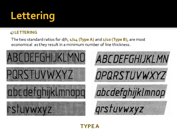
4) LETTERING
The two standard ratios for d/h, 1/14 (Type A) and
Lettering
4) LETTERING
The two standard ratios for d/h, 1/14 (Type A) and
Lettering
4) LETTERING
The two standard ratios for d/h, 1/14 (Type A) and
Lettering
4) LETTERING
The two standard ratios for d/h, 1/14 (Type A) and
Lettering
4) LETTERING
Numerical symbols
TYPE B
TYPE A
Lettering
4) LETTERING
Numerical symbols
TYPE B
TYPE A
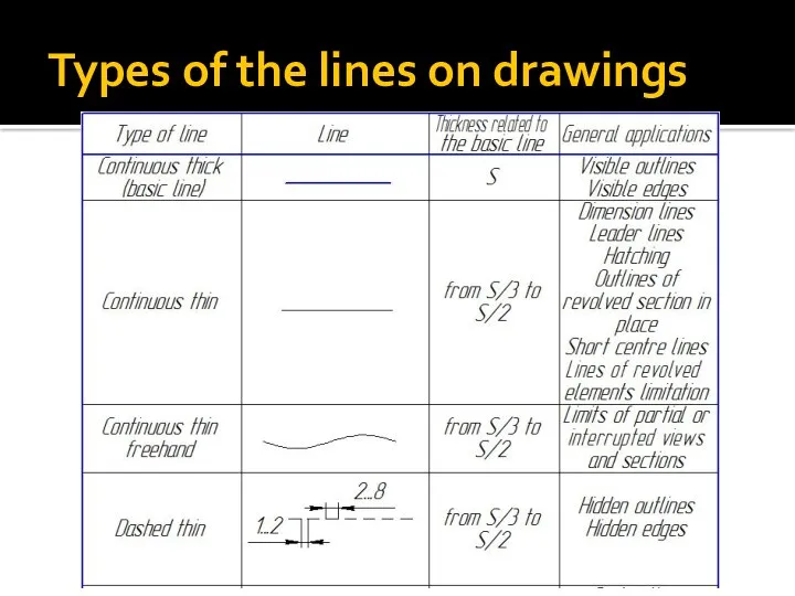
Types of the lines on drawings
Types of the lines on drawings
Technology Interactions
Computer-aided design uses computer systems to design products and create
Technology Interactions
Computer-aided design uses computer systems to design products and create
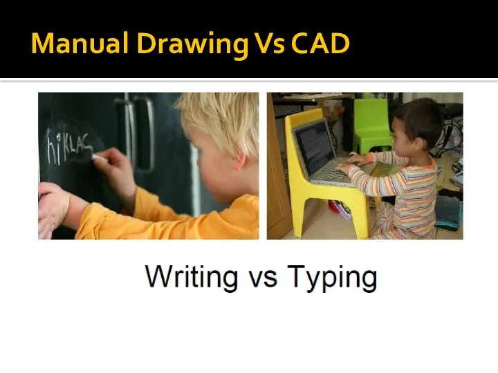
Manual Drawing Vs CAD
Manual Drawing Vs CAD
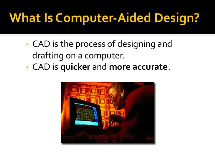
What Is Computer-Aided Design?
CAD is the process of designing and drafting
What Is Computer-Aided Design?
CAD is the process of designing and drafting
CAD Advantages
Saves time
Is more accurate
Improves team communications
CAD Advantages
Saves time
Is more accurate
Improves team communications
The CAD System
Hardware
Input devices, such as a keyboard and mouse
Output devices,
The CAD System
Hardware
Input devices, such as a keyboard and mouse
Output devices,
Two-Dimensional (2D) CAD
Can show only two dimensions of an object:
Width and
Two-Dimensional (2D) CAD
Can show only two dimensions of an object:
Width and
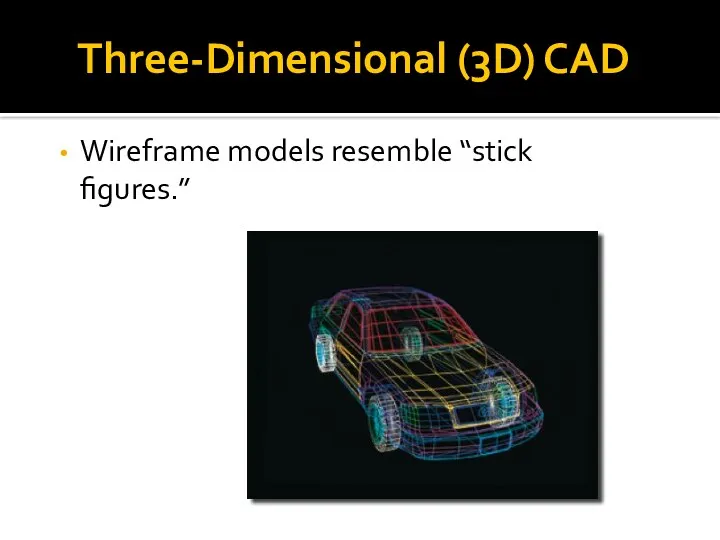
Three-Dimensional (3D) CAD
Wireframe models resemble “stick figures.”
Three-Dimensional (3D) CAD
Wireframe models resemble “stick figures.”
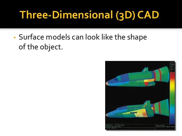
Three-Dimensional (3D) CAD
Surface models can look like the shape of the
Three-Dimensional (3D) CAD
Surface models can look like the shape of the
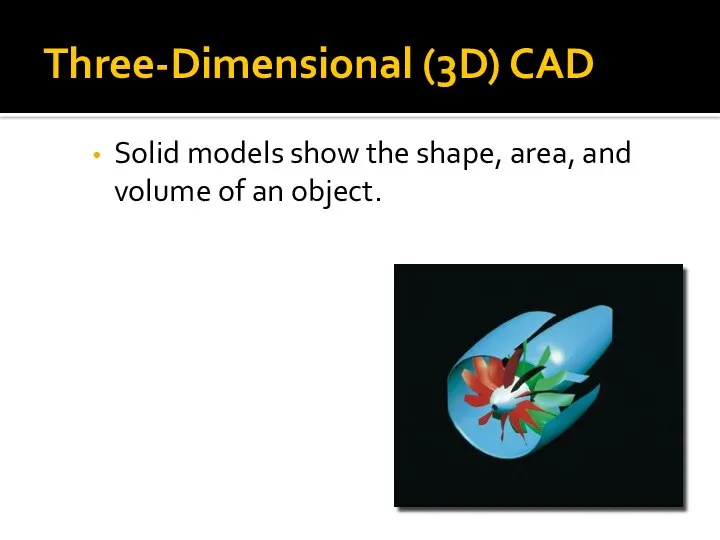
Three-Dimensional (3D) CAD
Solid models show the shape, area, and volume of
Three-Dimensional (3D) CAD
Solid models show the shape, area, and volume of
Using 3D CAD
Mechanical design
CAD/CAM
Rapid prototyping
Architectural design
Using 3D CAD
Mechanical design
CAD/CAM
Rapid prototyping
Architectural design
CAD/CAM
This process combines computer-aided design and computer-aided manufacturing.
CAD/CAM
This process combines computer-aided design and computer-aided manufacturing.
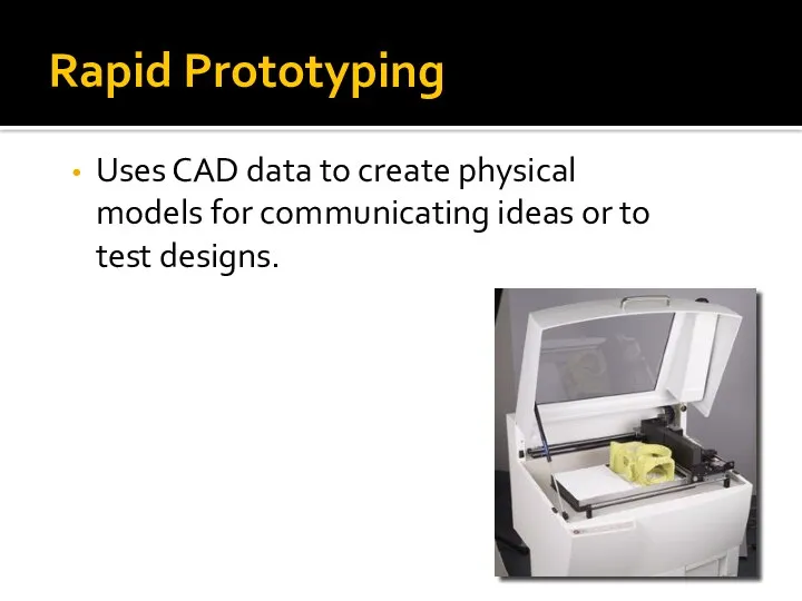
Rapid Prototyping
Uses CAD data to create physical models for communicating ideas
Rapid Prototyping
Uses CAD data to create physical models for communicating ideas
Introduction to
AutoCAD Engineering Drawings
Introduction to
AutoCAD Engineering Drawings
Introduction to CAD
AutoCAD
One of the most well-known 2D CAD software developed
Introduction to CAD
AutoCAD
One of the most well-known 2D CAD software developed
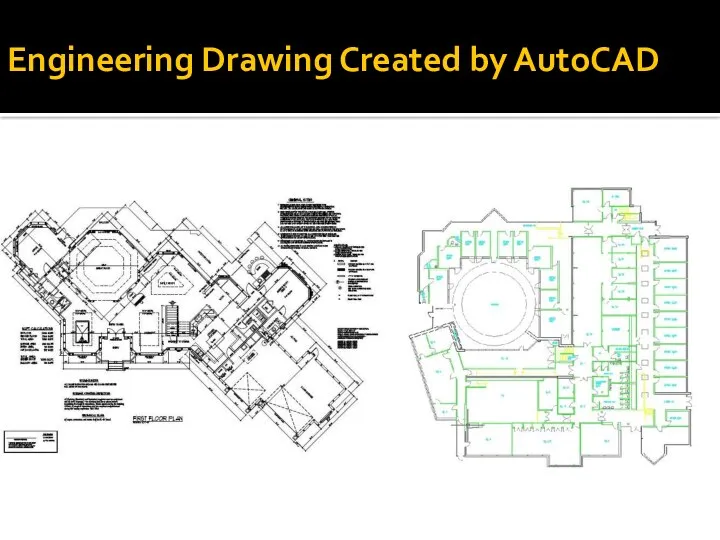
Engineering Drawing Created by AutoCAD
Engineering Drawing Created by AutoCAD
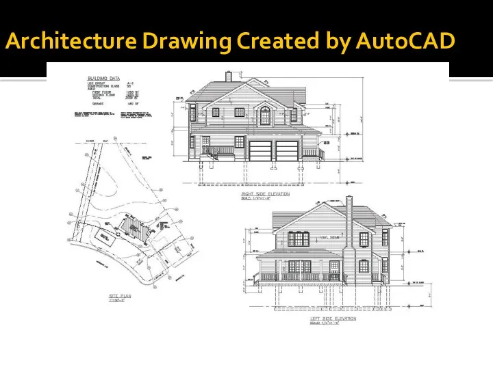
Architecture Drawing Created by AutoCAD
Architecture Drawing Created by AutoCAD
Starting AutoCAD
Start up > Autodesk > AutoCAD Mechanical 2015 > AutoCAD
Starting AutoCAD
Start up > Autodesk > AutoCAD Mechanical 2015 > AutoCAD
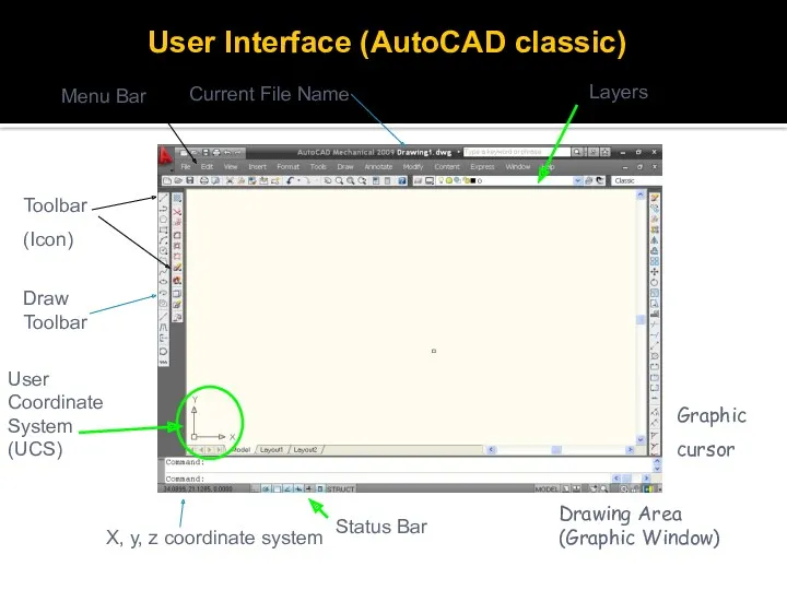
User Interface (AutoCAD classic)
Current File Name
Menu Bar
Toolbar
(Icon)
Layers
X, y, z coordinate system
Draw
User Interface (AutoCAD classic)
Current File Name
Menu Bar
Toolbar
(Icon)
Layers
X, y, z coordinate system
Draw
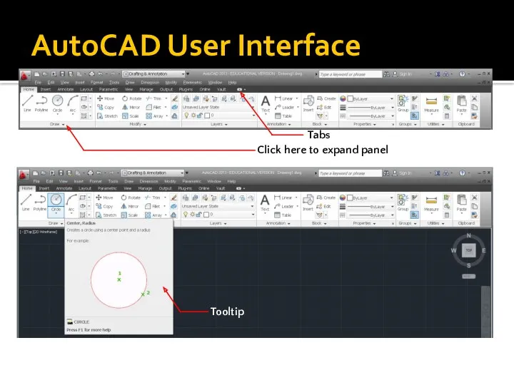
AutoCAD User Interface
Tabs
Click here to expand panel
Tooltip
AutoCAD User Interface
Tabs
Click here to expand panel
Tooltip
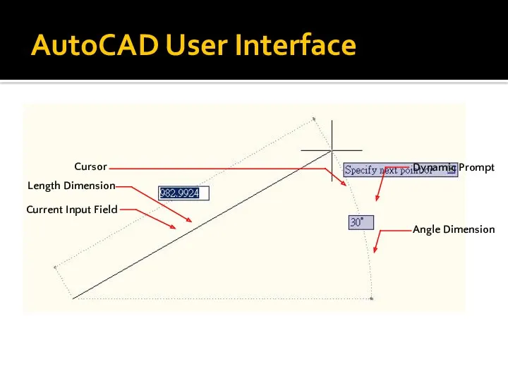
AutoCAD User Interface
Length Dimension
Cursor
Current Input Field
Dynamic Prompt
Angle Dimension
AutoCAD User Interface
Length Dimension
Cursor
Current Input Field
Dynamic Prompt
Angle Dimension
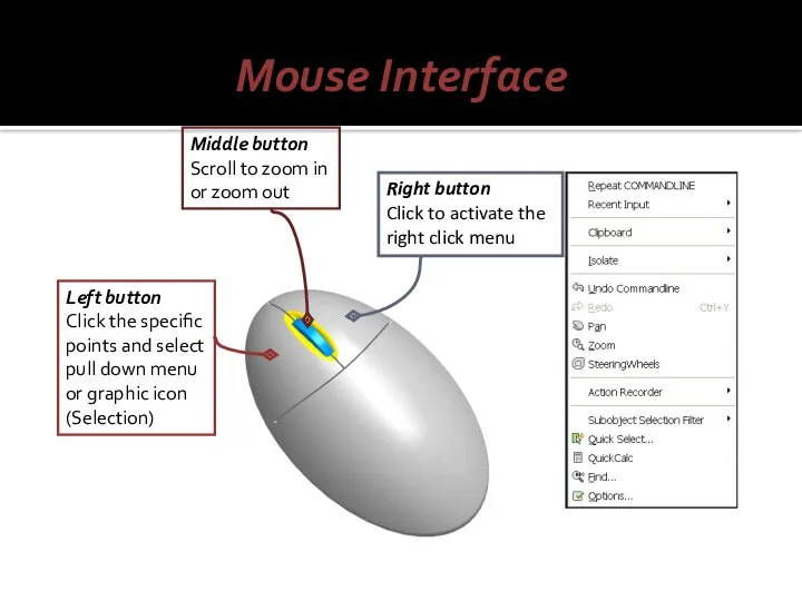
Mouse Interface
Left button
Click the specific points and select pull down
Mouse Interface
Left button
Click the specific points and select pull down
 Общие сведения об интегральных микросхемах
 Методы психологии
 Машиностроение России
 Современные представления о пространственном развитии степных регионов
 Презентация Родительского собрания
 Черепно – мозговые нервы
 Прокуратура Российской Федерации
 Певческие голоса
 Порядок организации сертификационных испытаний РЭА. Сертификационные испытания продукции и услуг
 Героем стать легко. Сдай кровь. Спаси жизнь
 Книга рекордов 1 Б
 Подтип Позвоночные (vertebrata), или Черепные (craniata)
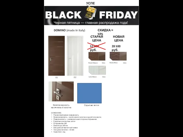 Domino (made in italy). Двери. Скидка -50%
 Татусю вітаємо тебе з днем народження
 Создание предметно –развивающей среды в ДОУ в первой младшей группе в соответствии ФГОС
 Презентация Осадки
 Стратегия пространственной реструктуризации жизнедеятельности современного города. Городская недвижимость
 Математика в футболе
 Основы религиозной культуры и светской этики
 Рельеф и полезные ископаемые Северной Америки.
 Учение о бытии
 Письменный прием вычитания вида 50 – 24
 История одного воинского захоронения
 Брахма - Самхита
 Общая характеристика и многообразие червей
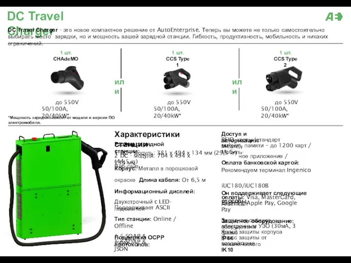 AE зарядные станции
 Ветер. Способ построения розы ветров
 Клиническая фармакология