- Typhoon Project Training Manual (Easytronics)

Содержание
- 2. 1. Precaution 1. All repairs should be done in accordance with the procedures described in this
- 3. 8. Never defeat any of the B+ voltage interlocks. Do not apply AC power to the
- 4. Concept : Two Convection Fan 2. Features and Specifications 2-1. Features * 230V 50Hz Grill :
- 5. 2. Features and Specifications 2-2. Control Panel revised Page
- 6. 2. Features and Specifications 2-3. Accessory revised Page
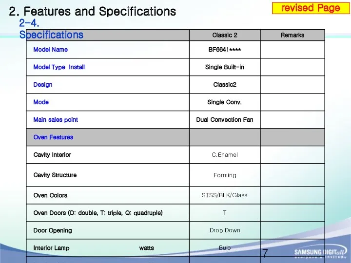
- 7. 2. Features and Specifications 2-4. Specifications revised Page
- 8. 2. Features and Specifications 2-4. Specifications revised Page
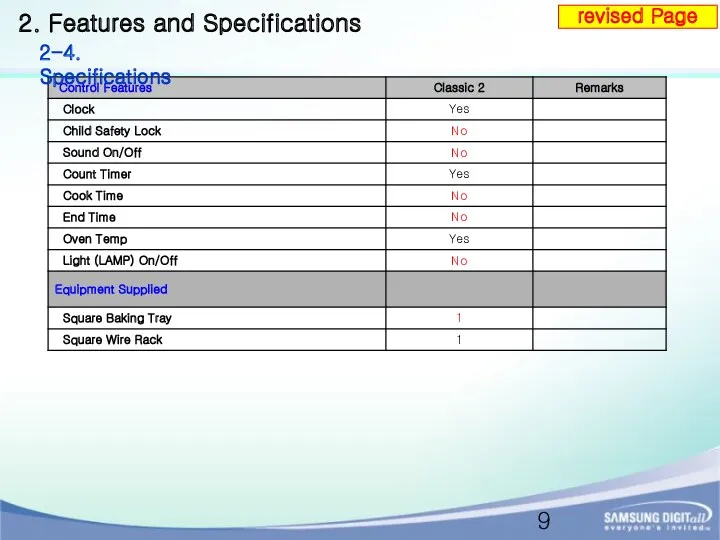
- 9. 2. Features and Specifications 2-4. Specifications revised Page
- 10. 3. Installation IMPORTANT Any electrical installation work must be carried out by a qualified electrician /
- 11. 3. Installation 3-2. The work in the low cabinet
- 12. 3. Installation 3-3. The work in the high cabinet
- 13. Connecting the oven to the power supply (H05VV-F, H05RR-F, Min 1.5~2.5 mm²) - Connections Electrical connections
- 14. 4. Function 4-1. Main function
- 15. 4. Function 4-2. Setting the Cooking Function mode revised Page
- 16. 4. Function 4-3. Other Function revised Page
- 17. 4. Function 4-3. Other Function revised Page
- 18. 5. Service Information 5-1. Thermo cut-out Two pieces of thermo cut-out are mounted in order to
- 19. 5. Service Information 5-2. PCB The operating power of Main PCB performs stable operation at a
- 20. 5. Service Information 5-2. PCB SMPS OUTPUT VOLTAGE Checkpoint(5V/12V) High Voltage area SSR for motor speed
- 21. 6. Disassembly and Reassembly 6 - 1 Replacement of Door Assembly
- 22. WARNING Whenever the door is separated from the oven, the clips should always be turned over.
- 23. 6-3-1 Take off the cap by turning counterclockwise. 6-3-2 Remove the metal ring and the sheet
- 24. 6 - 4 - 1 Remove a connector from the main PCB. 6. Disassembly and Reassembly
- 25. 6-4-2. Take off the three knob dial. 6. Disassembly and Reassembly 6 - 4 Replacement of
- 26. 6. Disassembly and Reassembly 6 - 4 Replacement of Assy Control revised Page
- 27. 6 - 5 - 1 Remove four screws from ass’y cover cooling motor both side.. 6.
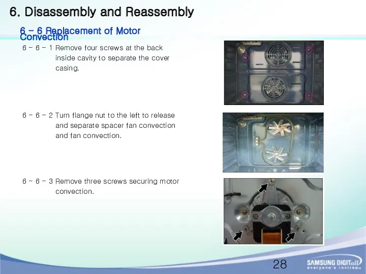
- 28. 6 - 6 - 1 Remove four screws at the back inside cavity to separate the
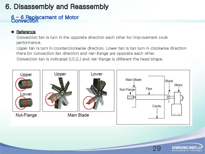
- 29. 6. Disassembly and Reassembly 6 - 6 Replacement of Motor Convection Reference Convection fan is turn
- 30. 6 - 7 - 1 Remove two screws securing heater convection twin at the rear. 6
- 31. 6 - 8 - 1 Remove two screws. 6 - 9 - 1 Remove two screws.
- 32. 6- 10 - 1 Remove one screw. 6 - 11 - 1 Remove each nut flange
- 33. 6 - 12 - 1 Remove one screw and pull forward to separate it. 6. Disassembly
- 34. 7. Troubleshooting 7-1 Power Failure
- 35. 7. Troubleshooting 7-2 PCB Failure
- 36. 7. Troubleshooting 7-2 PCB Failure (Continued)
- 37. 7. Troubleshooting 7-3 Failure of heating elements
- 38. 8. Schematic Diagram 8-1 Main PCB revised Page Please cut off the Main Power during dissamblling
- 39. 8. Schematic Diagram 8-2 SMPS Diagram revised Page
- 40. 8. Schematic Diagram 8-3 Temp Sensor revised Page
- 41. 8. Schematic Diagram 8-4 Relay Operation Diagram revised Page
- 42. 9. Wiring Diagram revised Page
- 43. 10. Q&A 10-1 Checkpoints before service request
- 44. 10. Q&A 10-2 Customer inquiry case and countermeasures
- 46. Скачать презентацию
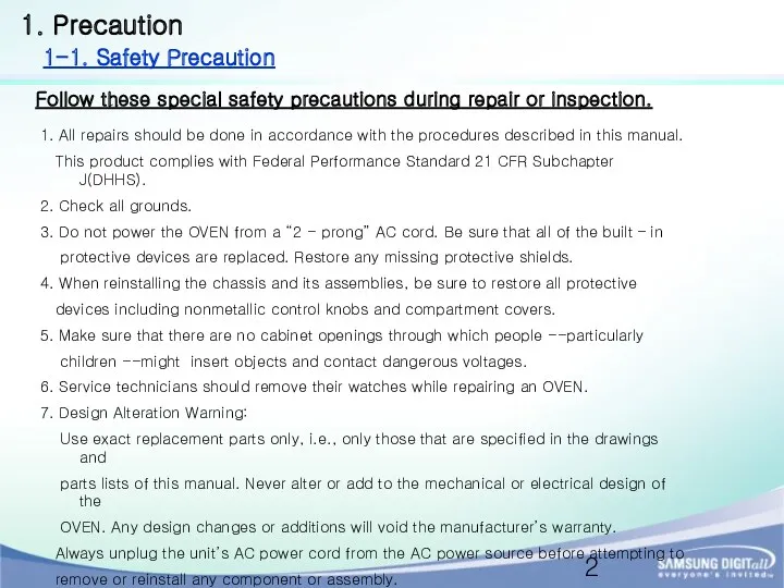
1. Precaution
1. All repairs should be done in accordance with the
1. Precaution
1. All repairs should be done in accordance with the
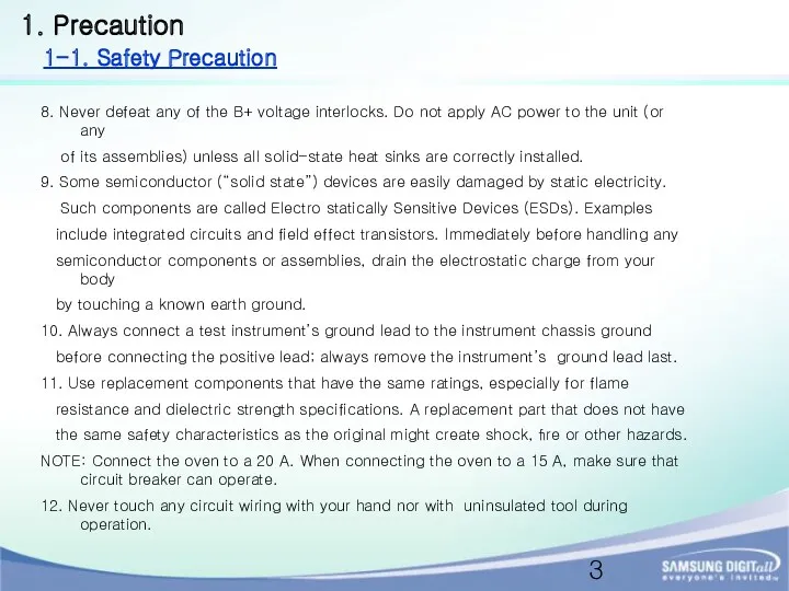
8. Never defeat any of the B+ voltage interlocks. Do not
8. Never defeat any of the B+ voltage interlocks. Do not
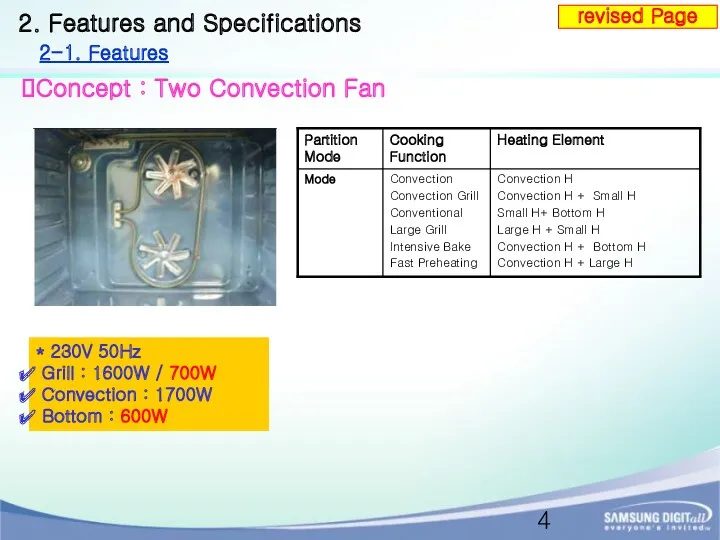
Concept : Two Convection Fan
2. Features and Specifications
2-1. Features
* 230V
Concept : Two Convection Fan
2. Features and Specifications
2-1. Features
* 230V
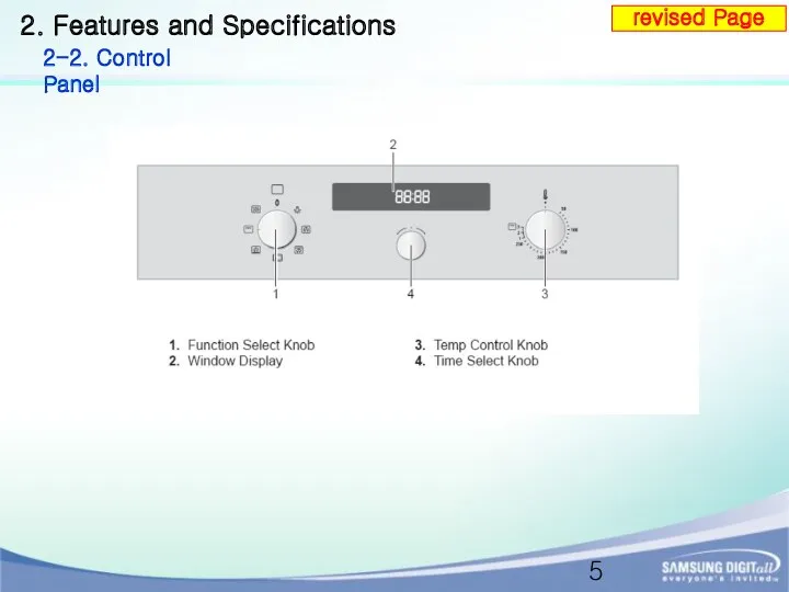
2. Features and Specifications
2-2. Control Panel
revised Page
2. Features and Specifications
2-2. Control Panel
revised Page
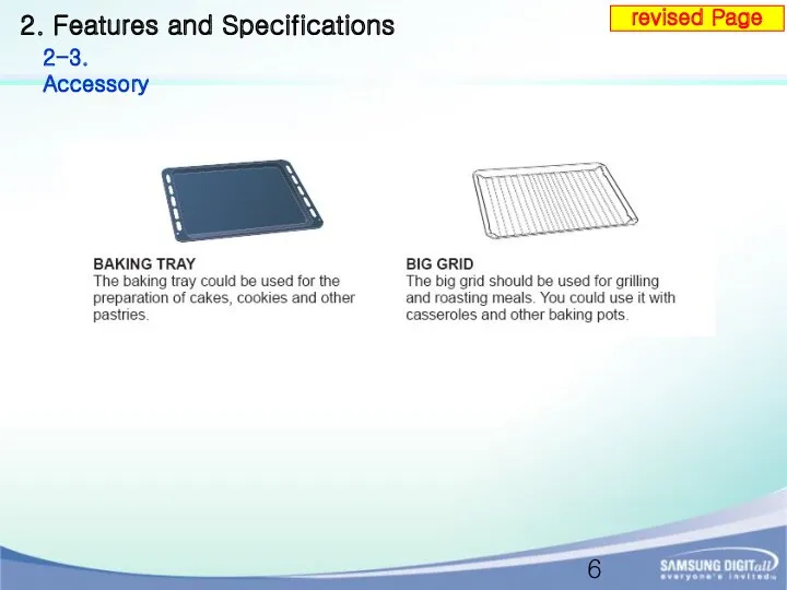
2. Features and Specifications
2-3. Accessory
revised Page
2. Features and Specifications
2-3. Accessory
revised Page
2. Features and Specifications
2-4. Specifications
revised Page
2. Features and Specifications
2-4. Specifications
revised Page
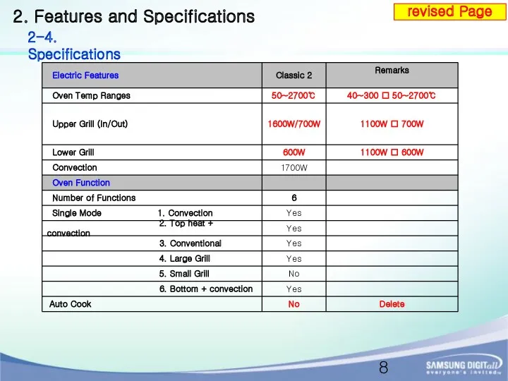
2. Features and Specifications
2-4. Specifications
revised Page
2. Features and Specifications
2-4. Specifications
revised Page
2. Features and Specifications
2-4. Specifications
revised Page
2. Features and Specifications
2-4. Specifications
revised Page
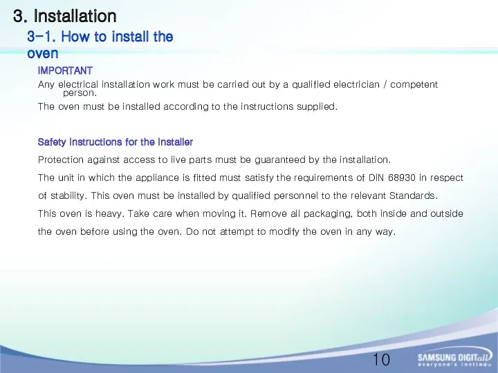
3. Installation
IMPORTANT
Any electrical installation work must be carried out by
3. Installation
IMPORTANT
Any electrical installation work must be carried out by
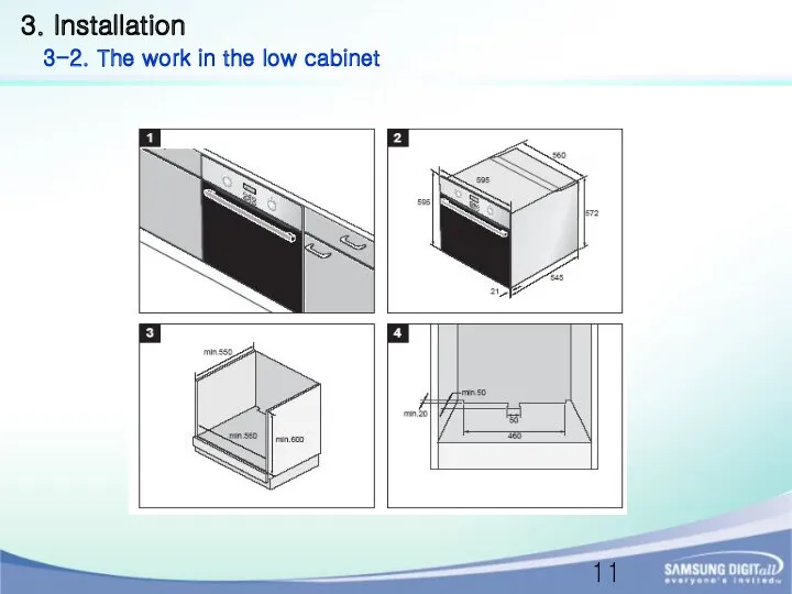
3. Installation
3-2. The work in the low cabinet
3. Installation
3-2. The work in the low cabinet
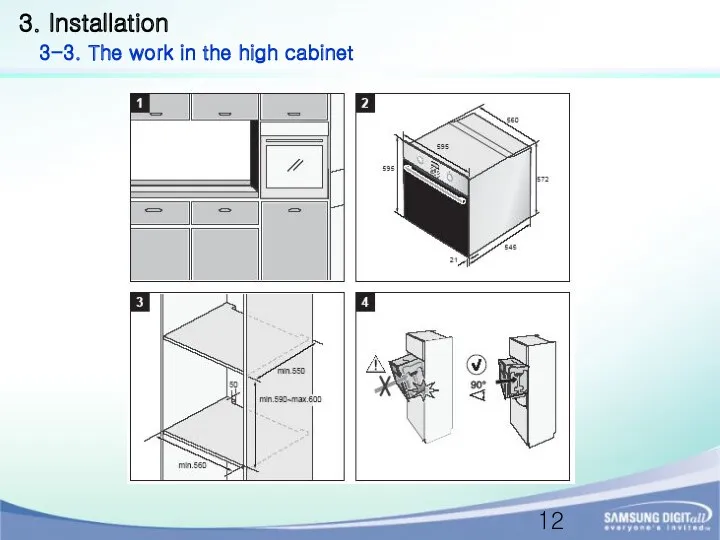
3. Installation
3-3. The work in the high cabinet
3. Installation
3-3. The work in the high cabinet
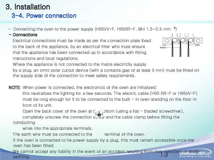
Connecting the oven to the power supply (H05VV-F, H05RR-F, Min 1.5~2.5
Connecting the oven to the power supply (H05VV-F, H05RR-F, Min 1.5~2.5
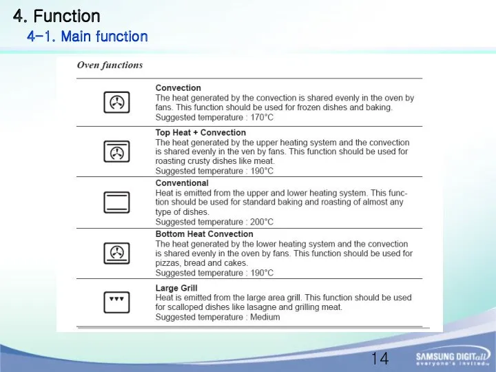
4. Function
4-1. Main function
4. Function
4-1. Main function
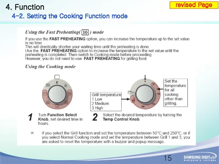
4. Function
4-2. Setting the Cooking Function mode
revised Page
4. Function
4-2. Setting the Cooking Function mode
revised Page
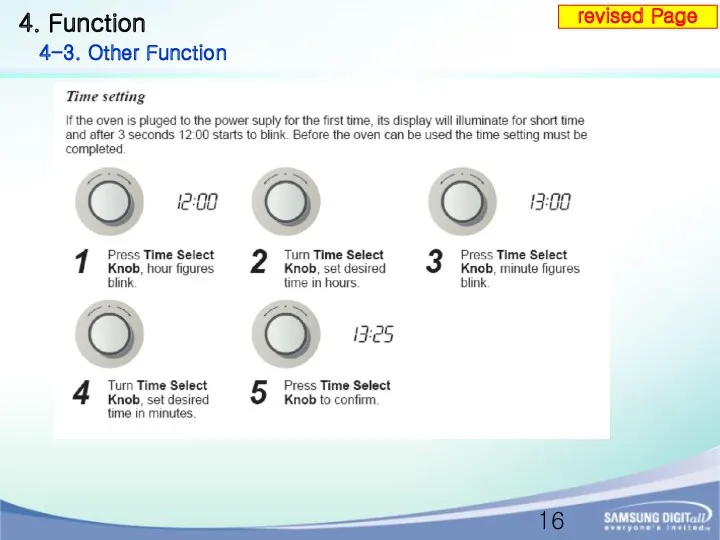
4. Function
4-3. Other Function
revised Page
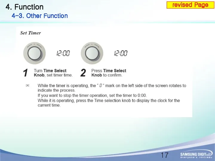
4. Function
4-3. Other Function
revised Page
4. Function
4-3. Other Function
revised Page
4. Function
4-3. Other Function
revised Page
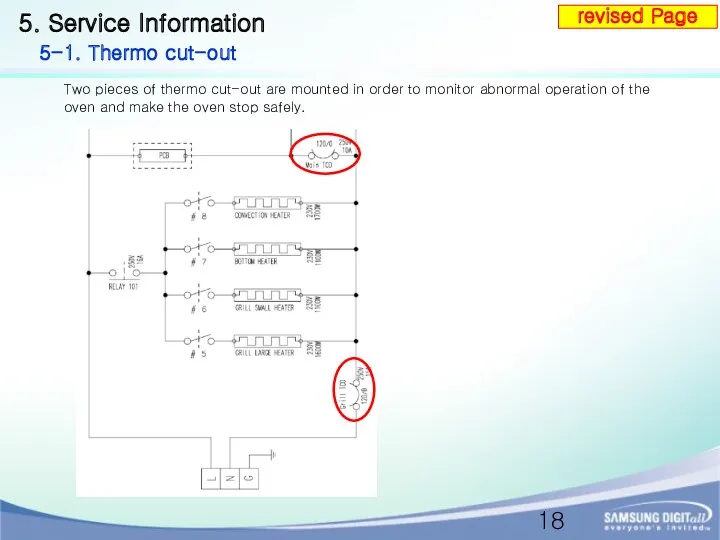
5. Service Information
5-1. Thermo cut-out
Two pieces of thermo cut-out are
5. Service Information
5-1. Thermo cut-out
Two pieces of thermo cut-out are
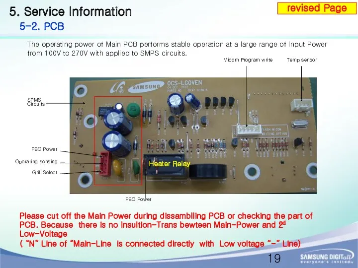
5. Service Information
5-2. PCB
The operating power of Main PCB performs
5. Service Information
5-2. PCB
The operating power of Main PCB performs
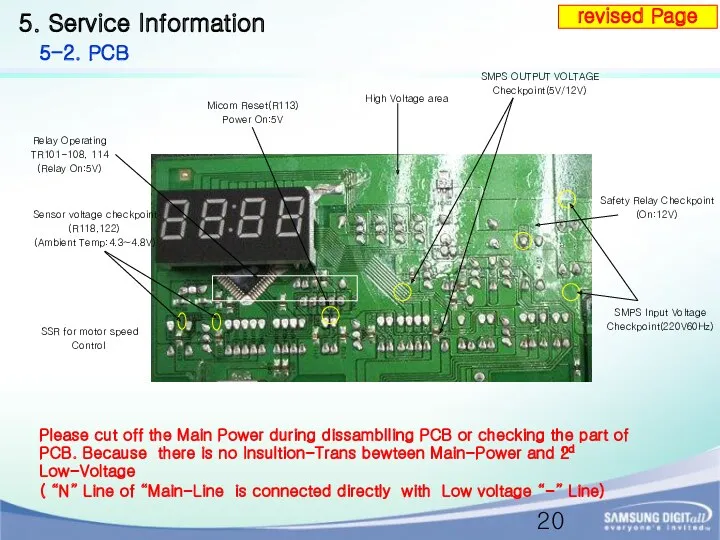
5. Service Information
5-2. PCB
SMPS OUTPUT VOLTAGE
Checkpoint(5V/12V)
High Voltage area
SSR for motor
5. Service Information
5-2. PCB
SMPS OUTPUT VOLTAGE
Checkpoint(5V/12V)
High Voltage area
SSR for motor
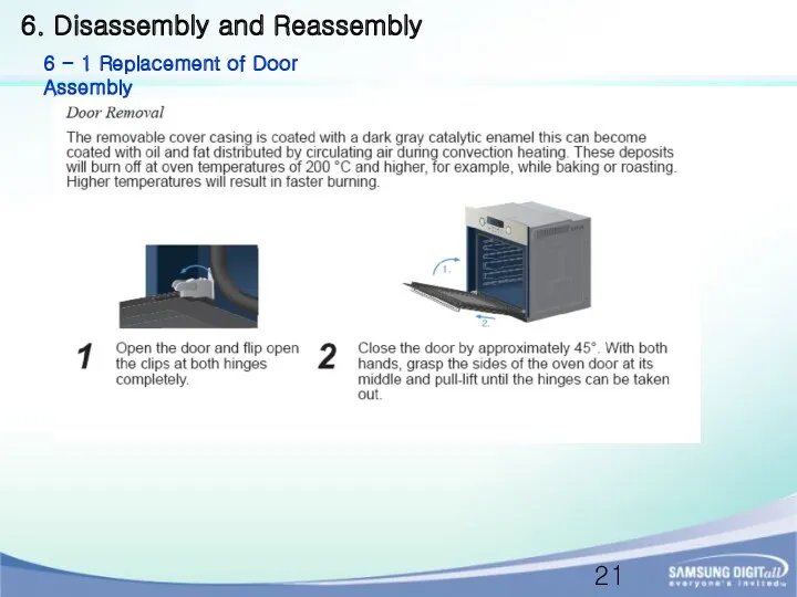
6. Disassembly and Reassembly
6 - 1 Replacement of Door Assembly
6. Disassembly and Reassembly
6 - 1 Replacement of Door Assembly
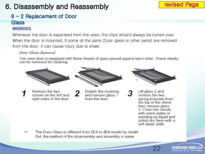
WARNING
Whenever the door is separated from the oven, the clips should
WARNING
Whenever the door is separated from the oven, the clips should
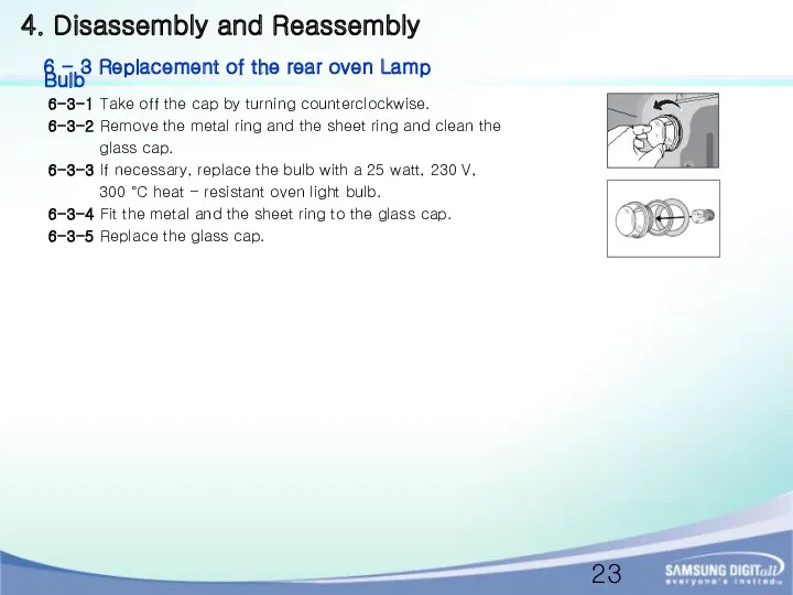
6-3-1 Take off the cap by turning counterclockwise.
6-3-2 Remove the metal
6-3-1 Take off the cap by turning counterclockwise.
6-3-2 Remove the metal
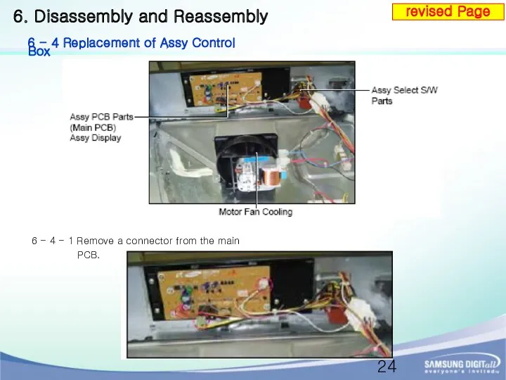
6 - 4 - 1 Remove a connector from the main
6 - 4 - 1 Remove a connector from the main
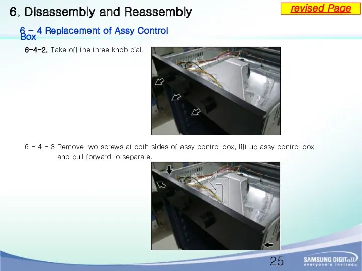
6-4-2. Take off the three knob dial.
6. Disassembly and Reassembly
6
6-4-2. Take off the three knob dial.
6. Disassembly and Reassembly
6
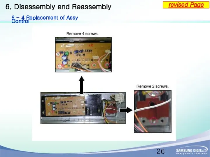
6. Disassembly and Reassembly
6 - 4 Replacement of Assy Control
revised
6. Disassembly and Reassembly
6 - 4 Replacement of Assy Control
revised
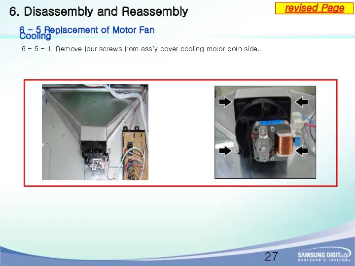
6 - 5 - 1 Remove four screws from ass’y cover
6 - 5 - 1 Remove four screws from ass’y cover
6 - 6 - 1 Remove four screws at the back
6 - 6 - 1 Remove four screws at the back
6. Disassembly and Reassembly
6 - 6 Replacement of Motor Convection
Reference
6. Disassembly and Reassembly
6 - 6 Replacement of Motor Convection
Reference
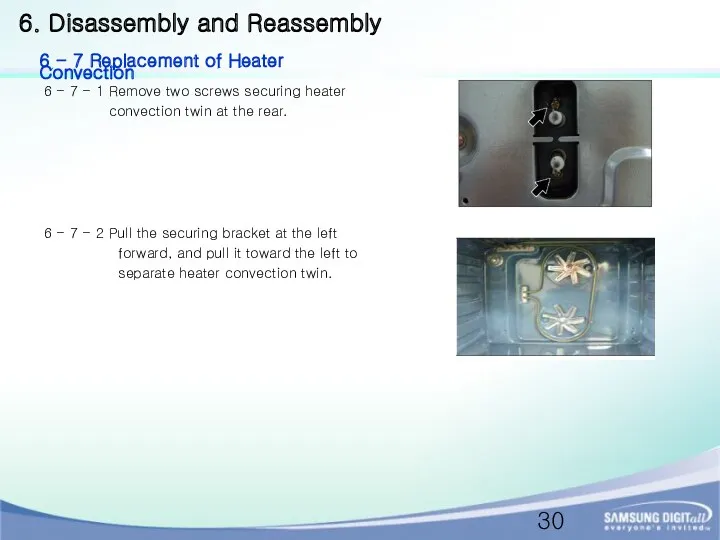
6 - 7 - 1 Remove two screws securing heater
convection
6 - 7 - 1 Remove two screws securing heater
convection
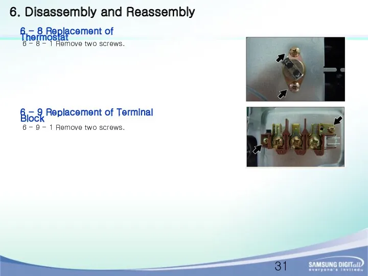
6 - 8 - 1 Remove two screws.
6 - 9 -
6 - 8 - 1 Remove two screws.
6 - 9 -
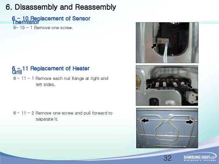
6- 10 - 1 Remove one screw.
6 - 11 - 1
6- 10 - 1 Remove one screw.
6 - 11 - 1
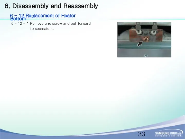
6 - 12 - 1 Remove one screw and pull forward
6 - 12 - 1 Remove one screw and pull forward
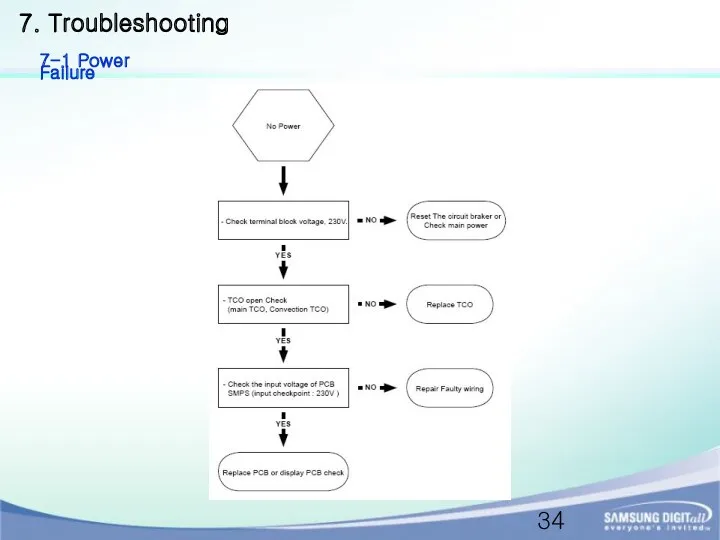
7. Troubleshooting
7-1 Power Failure
7. Troubleshooting
7-1 Power Failure
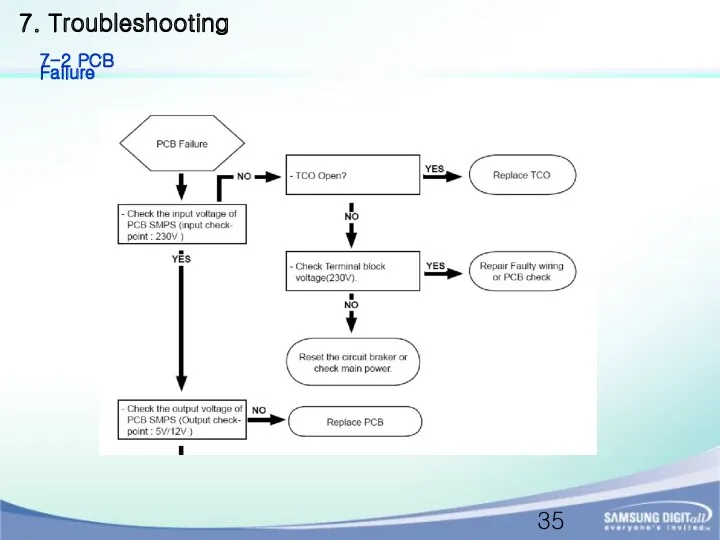
7. Troubleshooting
7-2 PCB Failure
7. Troubleshooting
7-2 PCB Failure
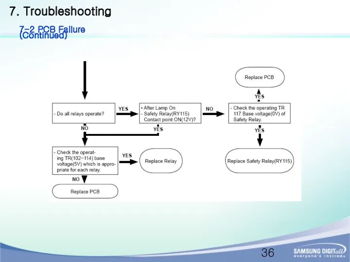
7. Troubleshooting
7-2 PCB Failure (Continued)
7. Troubleshooting
7-2 PCB Failure (Continued)
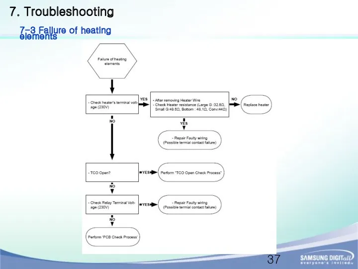
7. Troubleshooting
7-3 Failure of heating elements
7. Troubleshooting
7-3 Failure of heating elements
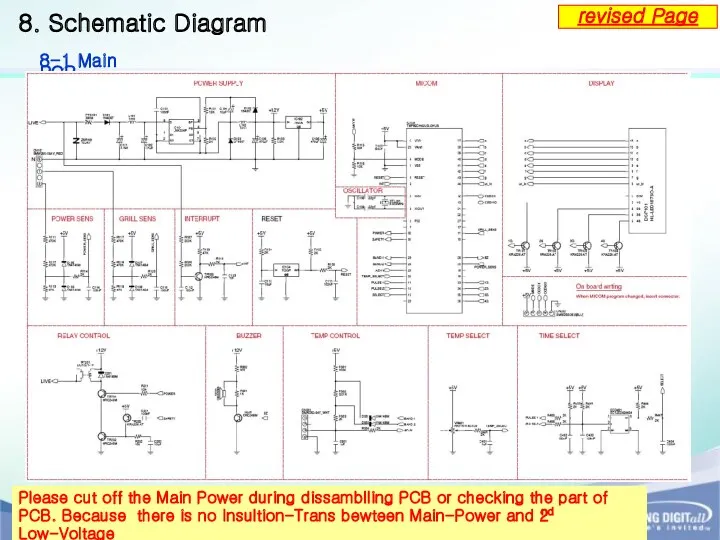
8. Schematic Diagram
8-1 Main PCB
revised Page
Please cut off the Main Power
8. Schematic Diagram
8-1 Main PCB
revised Page
Please cut off the Main Power
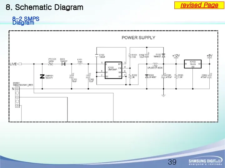
8. Schematic Diagram
8-2 SMPS Diagram
revised Page
8. Schematic Diagram
8-2 SMPS Diagram
revised Page
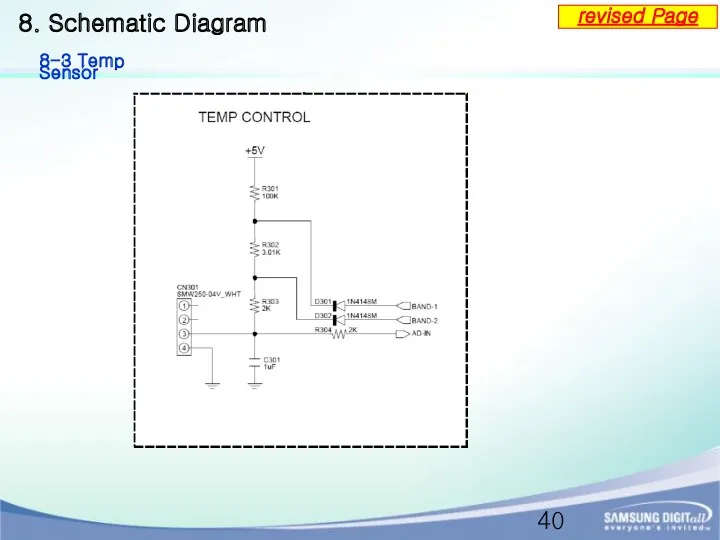
8. Schematic Diagram
8-3 Temp Sensor
revised Page
8. Schematic Diagram
8-3 Temp Sensor
revised Page
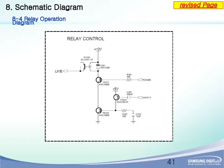
8. Schematic Diagram
8-4 Relay Operation Diagram
revised Page
8. Schematic Diagram
8-4 Relay Operation Diagram
revised Page
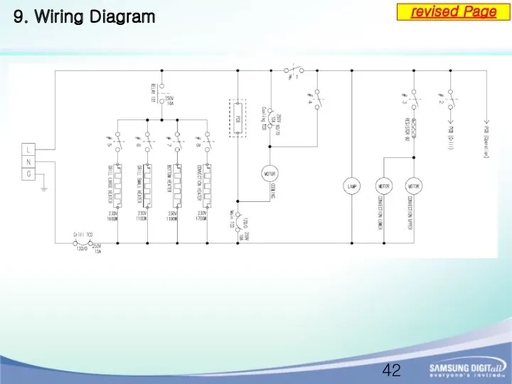
9. Wiring Diagram
revised Page
9. Wiring Diagram
revised Page
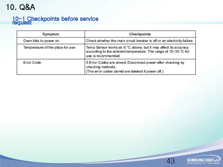
10. Q&A
10-1 Checkpoints before service request
10. Q&A
10-1 Checkpoints before service request
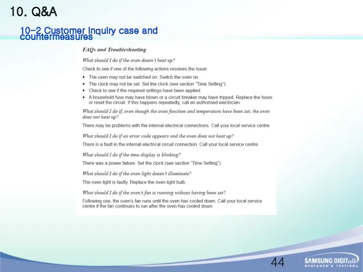
10. Q&A
10-2 Customer inquiry case and countermeasures
10. Q&A
10-2 Customer inquiry case and countermeasures
 Озон. Строение молекулы озона
 Приборы и устройства безопасности кранов
 Игры нашего поселка
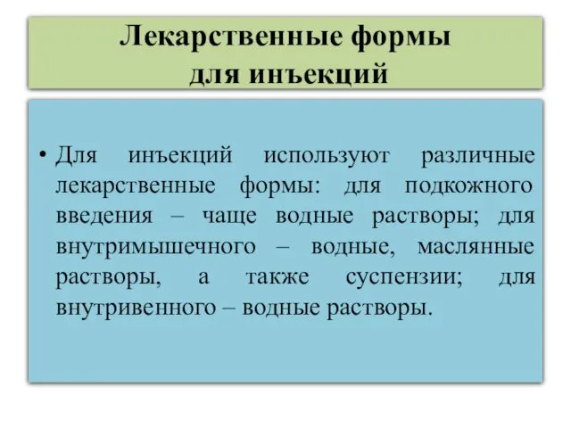 Лекарственные формы для инъекций
 Презентация Развитие личности ребенка в процессе приобщения к культурно-историческому наследию казачества
 Чрезвычайные ситуации и их характеристика. Основные понятия и определения
 Презентация Многоатомные спирты 10 класс
 Презентация к празднику Прощай, АЗБУКА!
 Вплив війни на психічне здоров'я 2
 Фестиваль народного творчества Донбасса
 Из истории наших предков. Боги славян.
 Колесо оценки урока.
 Беспроводные локальные сети
 Творчий проект Переборні задачі Паскаль
 Презентация Зимушка-Зима.
 Эти слайды описывают любовь к тебе
 Николай Иванович Сладков
 Театральное искусство XVII - XVIII вв и его виды
 Аргументы Шепли в большом споре
 Развитие произвольной памяти у детей старшего дошкольного возраста через дидактические игры
 Формирование простых запросов к готовой базе данных. (9 класс)
 ПРЕЗЕНТАЦИЯ по познавательному развитию ФЦКМ ДОРОГА ЖИЗНИ
 Первая медицинская помощь при кровотечении
 Программа технологических расчетов трубопроводов
 Внеурочная деятельность в младшей школе как важное условие реализации деятельности ФГОС нового поколения
  РАБОТЫ УЧАЩИХСЯ 7А класса по математике, информатике и ИКТ
 Покормите птиц зимой!!!
 Гавриил Романович Державин (1743-1816). Творчество Г. Р. Державина