- Vesta-P2a SP C360DNw

Содержание
- 2. Objectives After completing this training you should be able to: Install the SP C360 series in
- 3. Requirements SP C360DNw and SP C361SFNw Service manual This Presentation
- 4. Pre requisites & Exam Before starting this training you must already have followed the My-Ricoh training
- 5. 1. Product Outline
- 6. What Models? Vesta-P2a (M0B0) SP C360DNw sGW basic controller, 30 ppm, 28 ppm (duplex) Vesta-MF2a (D0A0,
- 7. New CTL: sGW concept SIMVA controller is changed to ‘’sGW’’ controller. ‘’sGW’’ controller has 2 concepts,
- 8. sGW CTL Basic function(Common with GW+)
- 9. sGW CTL Basic function(Differences with GW+)
- 10. sGW CTL Value-added functions
- 11. sGW CTL Hardware support
- 12. sGW CTL Cheetah Apps support Specific functions of Cheetah will be supported for MF models*. *sGW
- 13. sGW CTL Solution support
- 14. Main Points LED print head QSU fusing unit SPDF including ID card copy/scan Installation and maintenance
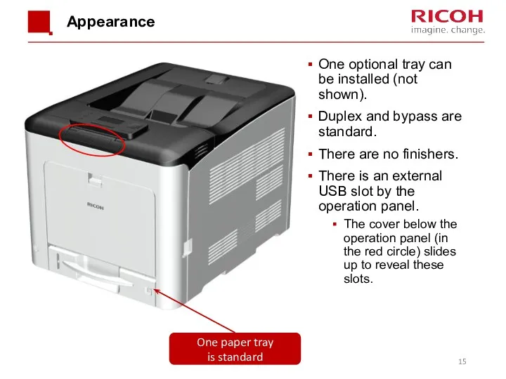
- 15. Appearance One optional tray can be installed (not shown). Duplex and bypass are standard. There are
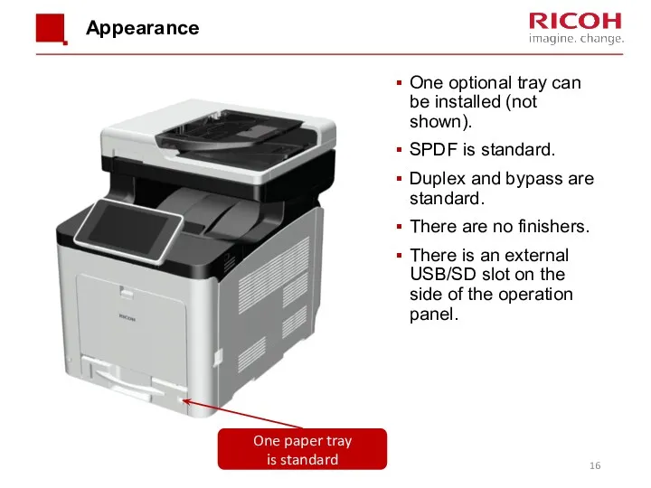
- 16. Appearance One optional tray can be installed (not shown). SPDF is standard. Duplex and bypass are
- 17. Hardware Options
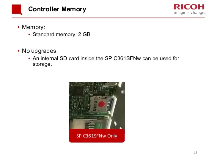
- 18. Controller Memory Memory: Standard memory: 2 GB No upgrades. An internal SD card inside the SP
- 19. Ports on the Controller Board (printer) USB port B: Use a USB cable to connect the
- 20. Ports on the Controller Board (MF) USB port B: Use a USB cable to connect the
- 21. General Specifications Input Tray Capacity Standard Tray:250 sheets Bypass tray: 100 sheets Optional Paper Feed Unit:
- 22. General Specifications (3/4) Paper Size: Standard tray: A4/LT SEF – A6/HLT LEF Non-standard sizes: Width: 82.5
- 23. General Specifications (4/4) Memory: 2 GB Interface Rear Ethernet interface (1000BASE-T/100BASE-TX/10BASE-T) x1 IEEE 802.11a/b/g/n wireless LAN
- 24. Targets
- 25. Yield of Consumables Toner K: 7k CMY: 5k Maintenance Parts See the ‘Maintenance Parts’ slide later
- 26. Black-and White Priority Mode If this function is enabled in user tool, color process control is
- 27. Curl Prevention Mode If the customer enables this function: Pre-rotation of the fusing unit is done
- 28. Safe Shutdown When the power switch is used to turn the power off, ‘Please Wait’ is
- 29. Forced Shutdown If the machine freezes, hold the power switch down for 6 seconds. However, this
- 30. 2. Maintenance
- 31. PM by User or Technician User PM: This product has been designed for user maintenance. The
- 32. Maintenance Parts PCDU K: 15k, CMY: 12k (User PM) K: 23k, CMY: 18k (Technician PM) Transfer
- 33. Near-end Alert for Maintenance Parts (Printer) Near-end for the maintenance parts can be selected in user
- 34. Near-end Alert for Maintenance Parts (MF) Same settings as Printer. To access on the MF:
- 35. What Happens at the End Alert? For toner cartridges and the waste toner bottle: When the
- 36. Other PM - PM Table Do the following, depending on the type of service contract. Cleaning
- 37. Updating Firmware The procedure uses SD cards and is the same as for other GW models.
- 38. 3. Detailed Section Descriptions
- 39. Machine Overview
- 40. Component Layout - Printer Operation Panel Paper Exit/Reverse Roller Toner Cartridge PCDU Engine Board and Controller
- 41. Component Layout - MF Operation Panel Paper Exit/Reverse Roller PCDU Toner Cartridge Engine Board and Controller
- 42. Component Layout - SPDF Pick Up Roller Feed Roller Pull-Out Roller Pre Scanning Roller Original front
- 43. Paper Path Bypass Tray Optional Paper Feed Tray Standard Paper Feed Tray Duplex Feed Path
- 44. Drive Components Transfer/Transport Motor Toner Supply Clutch (Y) Toner Supply Clutch (M) Toner Supply Clutch (C)
- 45. Scanner Drive Motor DF Drive Motor DF Feed Clutch SPDF & Scanner
- 46. Major Electrical Components (P&MF) PSU Main Power Switch NFC Board Speaker OPRB Fusing Fan New PCDU
- 47. Main Circuit Boards EGB (Engine Board): Controls the engine, the controller interface, image processing, color registration
- 48. Before Servicing the Machine Before you start to remove parts from the machine, do the following
- 49. Removing the Front Cover Unit This is a long procedure. It is only needed if the
- 50. Removing the Left Cover Remove the waste toner bottle before you remove the left cover. Otherwise
- 51. Replacing the EGB Remove the EEPROM from the old EGB and install it on the new
- 52. Don’t Loosen These Screws The photo below shows some screws painted in white. You can see
- 53. Replacing EEPROM on the EGB (1/2) When replacing the EEPROM on the Engine Board, please check
- 54. Replacing EEPROM on the EGB (2/2) If the EEPROM download/upload feature cannot be used, do the
- 55. Replacing the Controller Board Remove the NVRAM from the old board and install them on the
- 56. Image Creation
- 57. Overview An LED array [1] writes the latent image on the OPC [3]. Each OPC (K,
- 58. Components of the LED Array The LED array consists of the following parts. Sheet Base LED
- 59. Detailed Structure of the LED Array Tiny LEDs capable of creating images at 1200 dpi are
- 60. Notes Concerning the LED Array Image position adjustment Horizontal (main scan): Adjusted by moving the image
- 61. Troubleshooting Notes The LED heads are the same for all CMYK colors. So it is possible
- 62. Removing an LED Head After you open the upper inner cover, protect the PCDUs with a
- 63. Connecting the LED Arrays When you connect the flat cables from the EGB to the LED
- 64. Toner Cartridge and PCDU
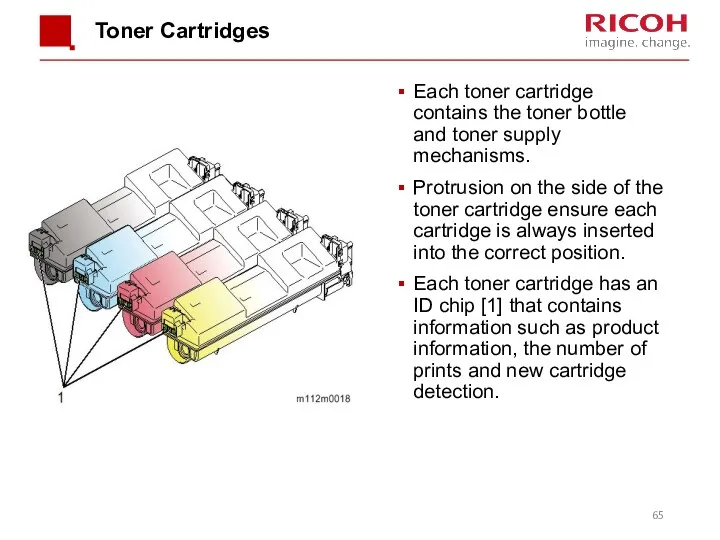
- 65. Toner Cartridges Each toner cartridge contains the toner bottle and toner supply mechanisms. Protrusion on the
- 66. Shutters Each cartridge has two shutters. Toner will not leave the cartridge until both shutters are
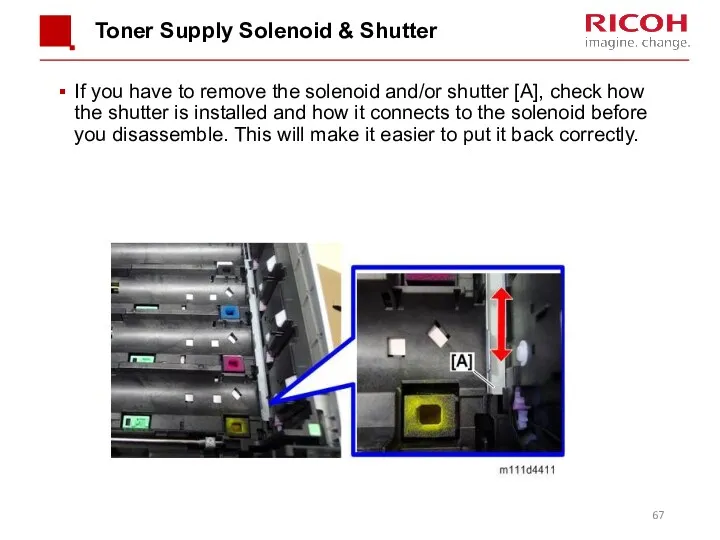
- 67. Toner Supply Solenoid & Shutter If you have to remove the solenoid and/or shutter [A], check
- 68. PCDU Layout The PCDU contains the charge roller, photoconductor, development mechanism, and cleaning unit. Upper Mixing
- 69. Toner Supply Mechanism When the toner supply clutch turns on, a coil in the toner cartridge
- 70. Toner Near End (TNE), Toner End (TE) - 1 The TE sensors are mounted on the
- 71. Toner Near End (TNE), Toner End (TE) - 2 After TNE, the toner end alert is
- 72. PCDU Drive The PCDUs are driven by the drum motor (K) [1], and the drum motor
- 73. Drum Charge and Cleaning This machine uses a charge roller [1]. The charge roller gives the
- 74. Development The development mechanism contains the development roller [1], the toner supply roller [2], and the
- 75. Mixing The toner moves as shown in the drawing below. The upper mixing coil [1] moves
- 76. Waste Toner Collection Toner waste within each PCDU is collected by the waste toner collection coil
- 77. New PCDU Detection A three-point terminal on the side of the cover detects when a new
- 78. Replacing the Toner End Sensor The toner end sensor is built into the LED print head.
- 79. Paper Feed
- 80. Overview Paper Feed Roller Friction Pad Bypass Feed Roller Bypass Friction Pad The rollers are replaced
- 81. Drive For paper feed, the machine turns on the paper feed clutch, and the paper feed
- 82. Tray Extension When shipped from the factory, sizes up to A4 SEF can be loaded in
- 83. Securing the End Fences There are 3 screw holes in the paper tray, to fix the
- 84. Securing the Side Fences There are 2 screw holes in the paper tray, to fix the
- 85. Paper Size Detection The paper size switch [2] detects actuators attached to the paper size dial
- 86. Bottom Plate Lift When you slide the paper feed tray into the unit, the bottom plate
- 87. Bypass Feed Bottom Plate Mechanism The bottom plate has an automatic lifting system. When the bypass
- 88. Bypass Feed Bypass Paper End Sensor Bypass Feed Roller Bypass feed uses a feed roller and
- 89. Vertical Feed Path Paper Exit Full Sensor Feeler Paper Exit/Reverse Roller Junction Gate Paper Exit Sensor
- 90. Duplex and Exit The fusing motor drives the fusing and paper exit rollers. The paper feed/transport
- 91. Solenoid (1/2) The solenoid has 2 functions: Operate the junction gate Operate the rotation direction of
- 92. Solenoid This diagram shows how the direction of the drive gears changes whether the solenoid is
- 93. Image Transfer
- 94. Overview The transfer section consists of three units: the Image Transfer Unit [1], the Image Transfer
- 95. Image Transfer Belt Unit The transfer/transport motor [2] drives the ITB drive roller [3] via a
- 96. Transfer Belt Contact Mechanism For monochrome printing, the image transfer belt is disengaged from the color
- 97. Belt Guide Roller In previous models, this roller [5] was inside the ITB unit. However, for
- 98. Transfer Belt Cleaning The transfer cleaning blade [1] removes remaining toner from the belt surface. The
- 99. Paper Transfer Roller Unit The bias applied to the paper transfer roller [2] pulls the toner
- 100. Transfer Roller Cleaning Toner may transfer to the roller surface following a paper jam or if
- 101. Paper Separation During paper transfer, the transfer roller [A] applies a static charge to the paper
- 102. New ITB Unit Detection The ITB new unit detection mechanism is not present in the service
- 103. Putting the ITB Unit Back in the Machine Before you install the image transfer belt, make
- 104. Installing a New ITB Unit Print out the logging data using SP5-990-004 before you replace the
- 105. Installing a New Paper Transfer Roller Print out the logging data using SP5-990-004 before you replace
- 106. Installing a New Transfer Belt Cleaning Unit When you change the transfer belt cleaning unit, dust
- 107. Installing a New Transfer Belt Cleaning Unit When you remove the transfer belt cleaning unit back
- 108. Fusing
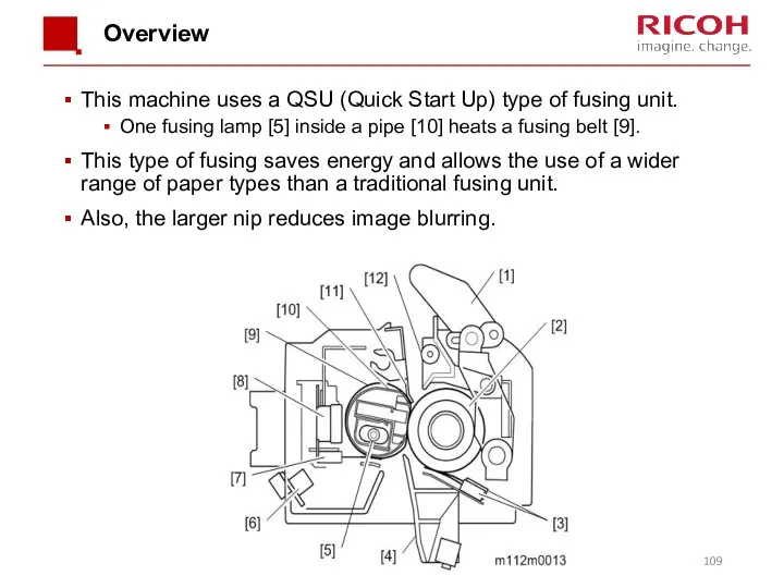
- 109. Overview This machine uses a QSU (Quick Start Up) type of fusing unit. One fusing lamp
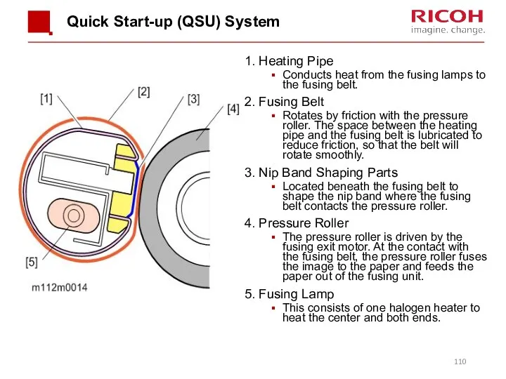
- 110. Quick Start-up (QSU) System 1. Heating Pipe Conducts heat from the fusing lamps to the fusing
- 111. Fusing Unit Drive The fusing motor [1] drives the pressure roller [2], fusing belt [3], and
- 112. New Unit Detection This is done using a fuse [2] on the rear frame [3] of
- 113. Pressure Release A pressure release mechanism makes it easy to remove paper jams in the fusing
- 114. Fusing Temperature Control A thermostat [3] and a non-contact thermistor [1] monitor the fusing belt temperature.
- 115. Fusing Temperature Control Warming-up Mode Fusing warm-up begins after the machine power is switched on. The
- 116. Fusing Temperature Control Print Mode The fusing temperature increases to the “print ready temperature”, and printing
- 117. Fusing Temperature Control Wait Mode The fusing lamp and the fusing motor turn OFF after a
- 118. Fusing Temperature Control PPM Down Mode PPM down control changes the feed timing to create a
- 119. Waste Toner Collection
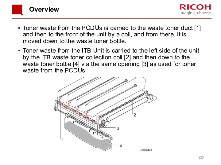
- 120. Overview Toner waste from the PCDUs is carried to the waste toner duct [1], and then
- 121. Drive The ITB waste toner collection coil [2] is driven via the drive roller in the
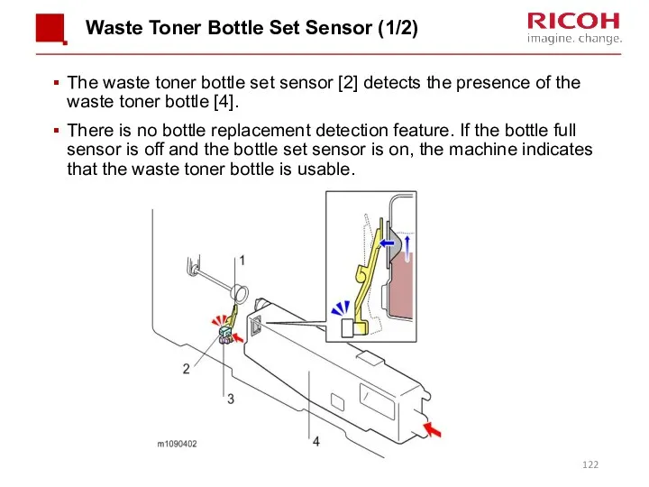
- 122. Waste Toner Bottle Set Sensor (1/2) The waste toner bottle set sensor [2] detects the presence
- 123. Waste Toner Bottle Full Sensor (2/2) When waste toner exceeds a certain amount, the rubber portion
- 124. Toner Bottle Full The pixel count corresponds to a number of sheets that can be printed
- 125. Lubricant A small amount of yellow toner is applied to the rubber component shown below with
- 126. Replacement Either the customer or the technician can replace the toner collection bottle. The counter for
- 127. Process Control
- 128. Processes Process control Development bias control Toner supply control MUSIC The toner mark sensors (TM (ID)
- 129. TM (ID) Sensors Below the image transfer belt, there are two TM (ID) (Toner Mark) sensors.
- 130. Replacing the TM (ID) Sensors (1/3) Note that the sensor seen on the left [L] (as
- 131. Replacing the TM (ID) Sensors (2/3) Before replacement: Each sensor has a label with some numbers
- 132. Replacing the TM (ID) Sensors (3/3) After replacement: Execute SP3-011-004 (Adjustment manual exe. Full Music /
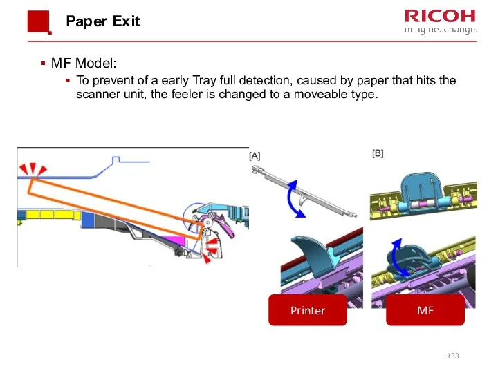
- 133. Paper Exit MF Model: To prevent of a early Tray full detection, caused by paper that
- 135. Скачать презентацию
Objectives
After completing this training you should be able to:
Install the SP
Objectives
After completing this training you should be able to:
Install the SP
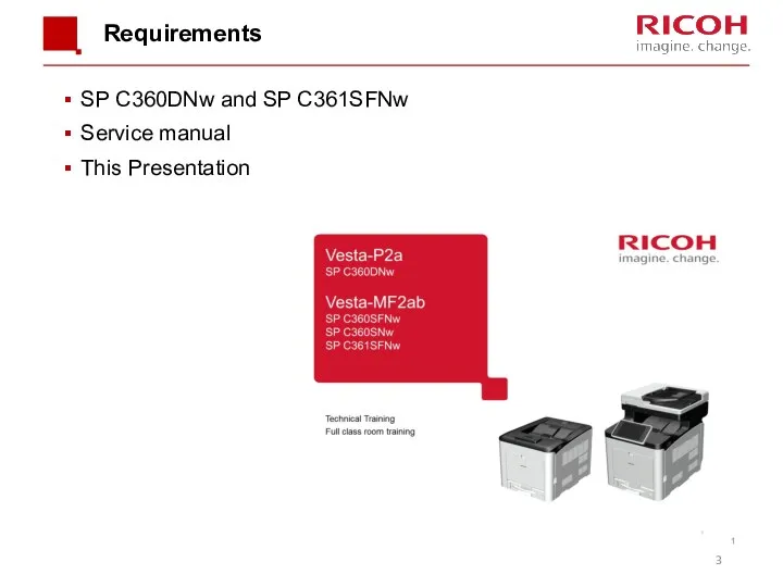
Requirements
SP C360DNw and SP C361SFNw
Service manual
This Presentation
Requirements
SP C360DNw and SP C361SFNw
Service manual
This Presentation
Pre requisites & Exam
Before starting this training you must already have
Pre requisites & Exam
Before starting this training you must already have

1. Product Outline
1. Product Outline
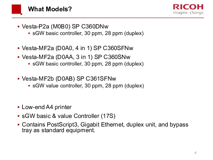
What Models?
Vesta-P2a (M0B0) SP C360DNw
sGW basic controller, 30 ppm, 28
What Models?
Vesta-P2a (M0B0) SP C360DNw
sGW basic controller, 30 ppm, 28
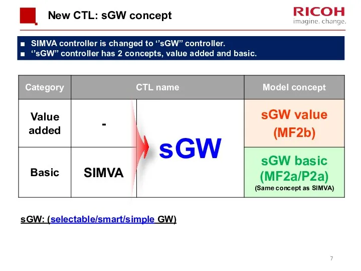
New CTL: sGW concept
SIMVA controller is changed to ‘’sGW’’ controller.
‘’sGW’’ controller
New CTL: sGW concept
SIMVA controller is changed to ‘’sGW’’ controller.
‘’sGW’’ controller
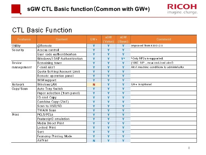
sGW CTL Basic function(Common with GW+)
sGW CTL Basic function(Common with GW+)
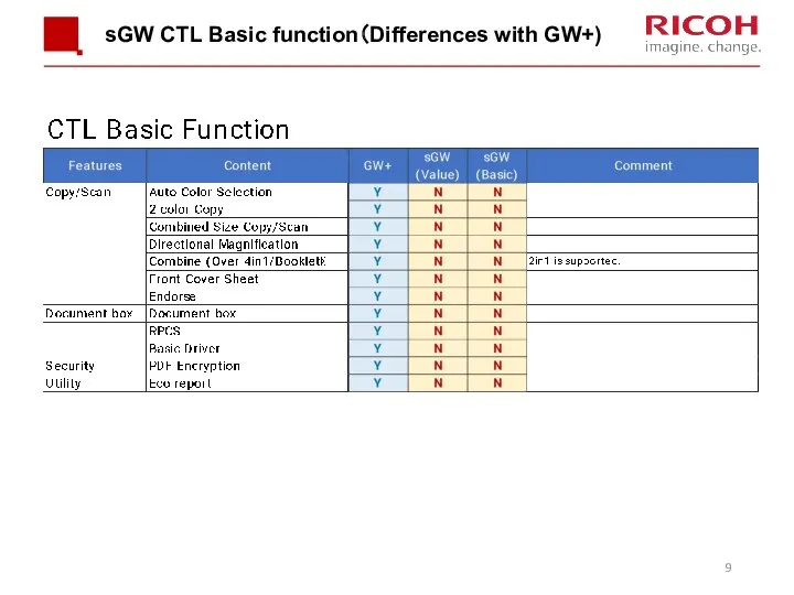
sGW CTL Basic function(Differences with GW+)
sGW CTL Basic function(Differences with GW+)
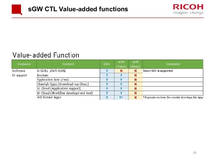
sGW CTL Value-added functions
sGW CTL Value-added functions
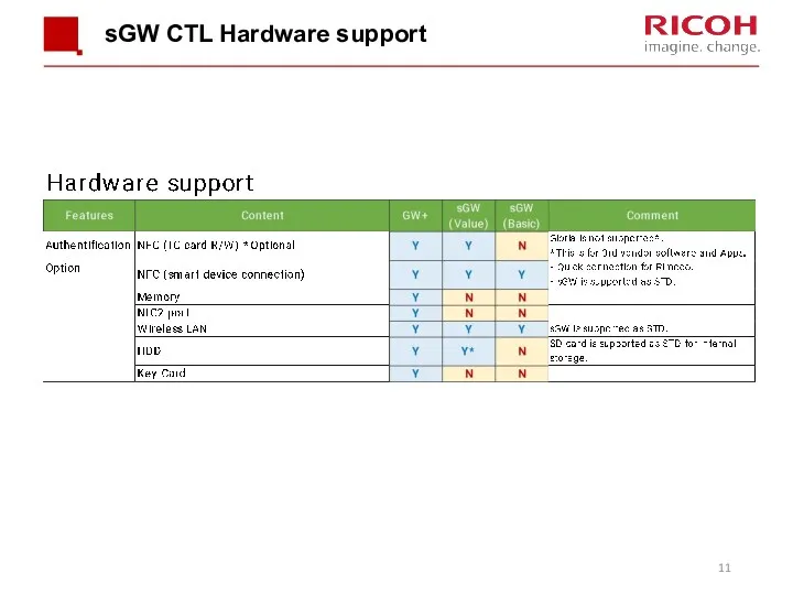
sGW CTL Hardware support
sGW CTL Hardware support
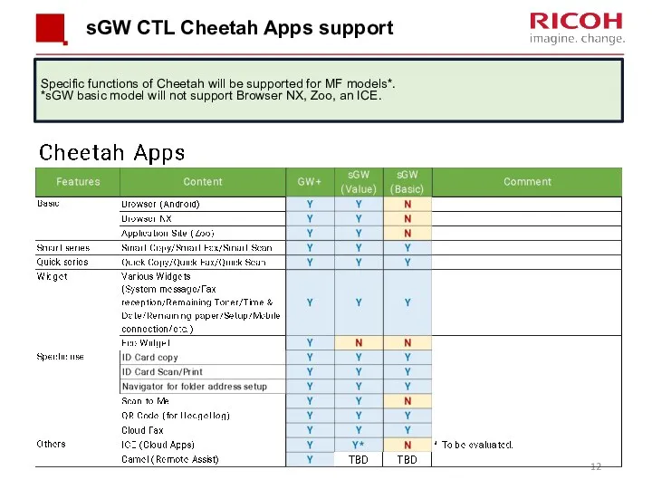
sGW CTL Cheetah Apps support
Specific functions of Cheetah will be supported
sGW CTL Cheetah Apps support
Specific functions of Cheetah will be supported
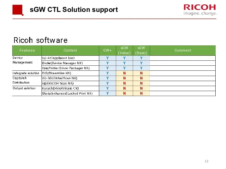
sGW CTL Solution support
sGW CTL Solution support
Main Points
LED print head
QSU fusing unit
SPDF including ID card copy/scan
Installation and
Main Points
LED print head
QSU fusing unit
SPDF including ID card copy/scan
Installation and
Appearance
One optional tray can be installed (not shown).
Duplex and bypass are
Appearance
One optional tray can be installed (not shown).
Duplex and bypass are
Appearance
One optional tray can be installed (not shown).
SPDF is standard.
Duplex and
Appearance
One optional tray can be installed (not shown).
SPDF is standard.
Duplex and
Hardware Options
Hardware Options
Controller Memory
Memory:
Standard memory: 2 GB
No upgrades.
An internal SD card inside the
Controller Memory
Memory:
Standard memory: 2 GB
No upgrades.
An internal SD card inside the
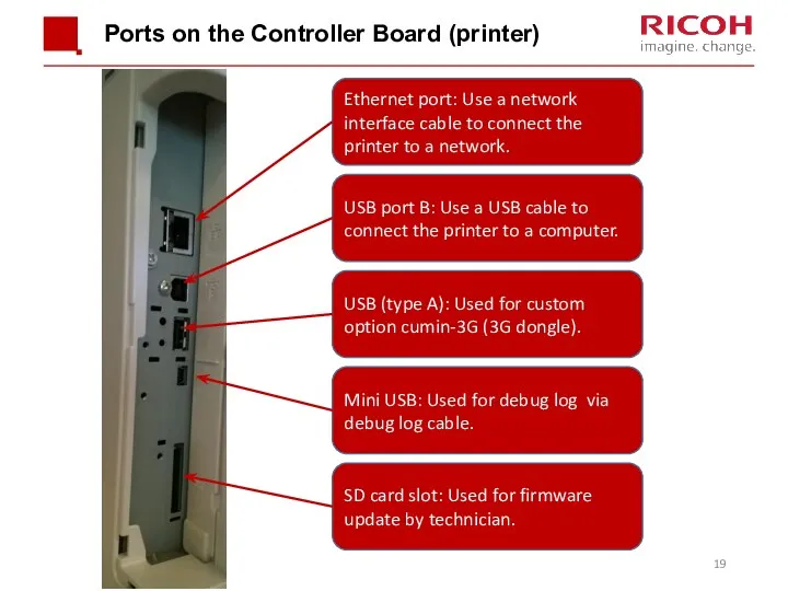
Ports on the Controller Board (printer)
USB port B: Use a USB
Ports on the Controller Board (printer)
USB port B: Use a USB
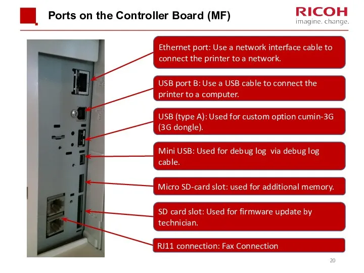
Ports on the Controller Board (MF)
USB port B: Use a USB
Ports on the Controller Board (MF)
USB port B: Use a USB
General Specifications
Input Tray Capacity
Standard Tray:250 sheets
Bypass tray: 100 sheets
Optional Paper
General Specifications
Input Tray Capacity
Standard Tray:250 sheets
Bypass tray: 100 sheets
Optional Paper
General Specifications (3/4)
Paper Size:
Standard tray: A4/LT SEF – A6/HLT LEF
Non-standard
General Specifications (3/4)
Paper Size:
Standard tray: A4/LT SEF – A6/HLT LEF
Non-standard
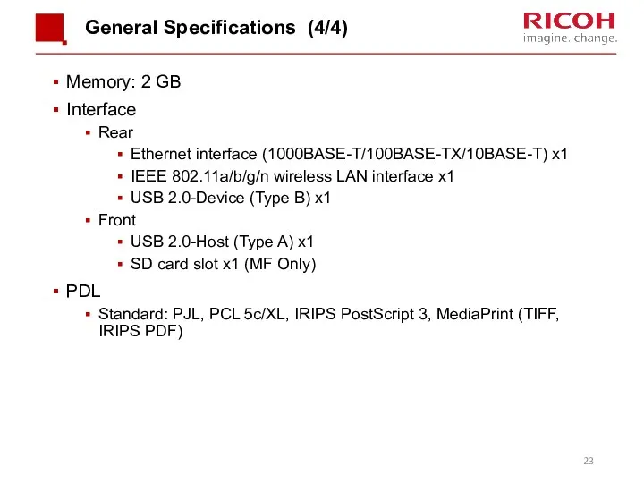
General Specifications (4/4)
Memory: 2 GB
Interface
Rear
Ethernet interface (1000BASE-T/100BASE-TX/10BASE-T) x1
IEEE 802.11a/b/g/n wireless LAN
General Specifications (4/4)
Memory: 2 GB
Interface
Rear
Ethernet interface (1000BASE-T/100BASE-TX/10BASE-T) x1
IEEE 802.11a/b/g/n wireless LAN
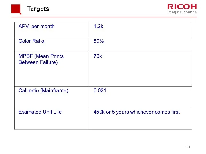
Targets
Targets
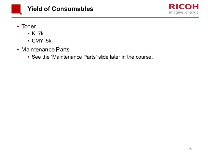
Yield of Consumables
Toner
K: 7k
CMY: 5k
Maintenance Parts
See the ‘Maintenance Parts’ slide later
Yield of Consumables
Toner
K: 7k
CMY: 5k
Maintenance Parts
See the ‘Maintenance Parts’ slide later
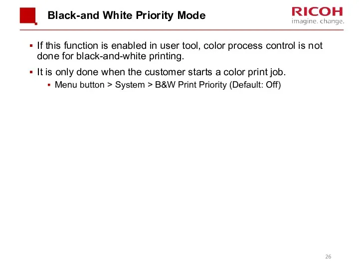
Black-and White Priority Mode
If this function is enabled in user tool,
Black-and White Priority Mode
If this function is enabled in user tool,
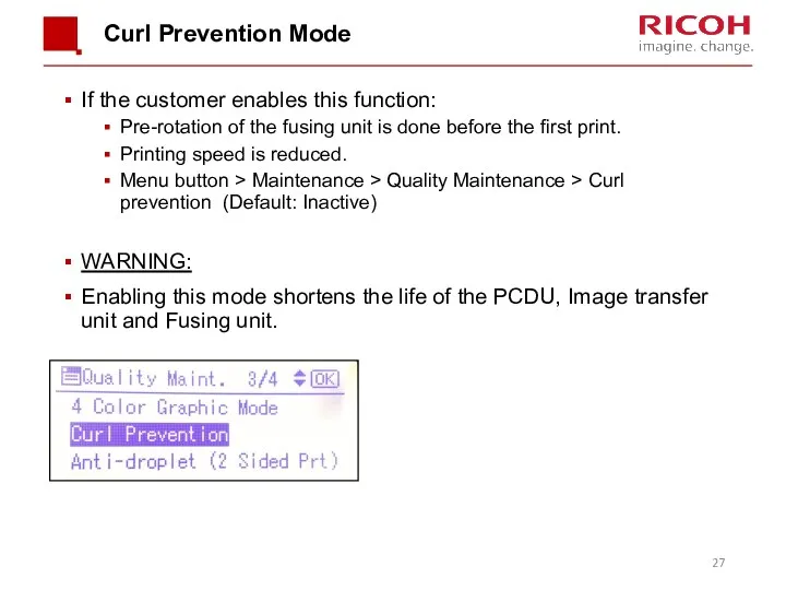
Curl Prevention Mode
If the customer enables this function:
Pre-rotation of the fusing
Curl Prevention Mode
If the customer enables this function:
Pre-rotation of the fusing
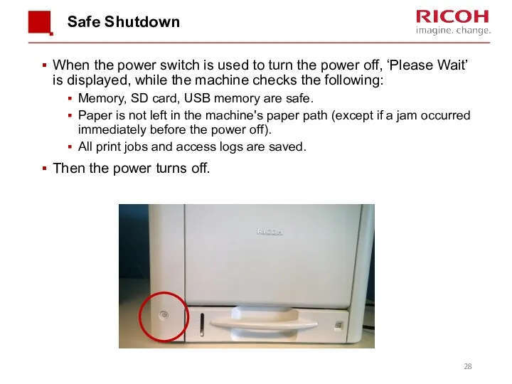
Safe Shutdown
When the power switch is used to turn the power
Safe Shutdown
When the power switch is used to turn the power
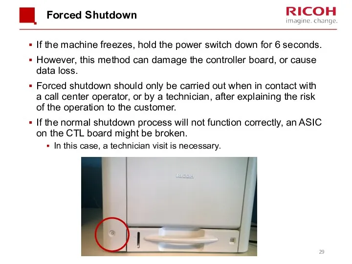
Forced Shutdown
If the machine freezes, hold the power switch down for
Forced Shutdown
If the machine freezes, hold the power switch down for

2. Maintenance
2. Maintenance
PM by User or Technician
User PM:
This product has been designed for
PM by User or Technician
User PM:
This product has been designed for
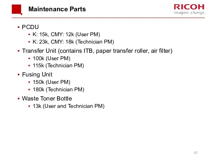
Maintenance Parts
PCDU
K: 15k, CMY: 12k (User PM)
K: 23k, CMY: 18k (Technician
Maintenance Parts
PCDU
K: 15k, CMY: 12k (User PM)
K: 23k, CMY: 18k (Technician
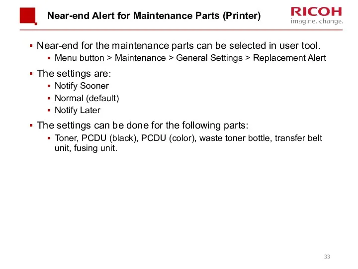
Near-end Alert for Maintenance Parts (Printer)
Near-end for the maintenance parts can
Near-end Alert for Maintenance Parts (Printer)
Near-end for the maintenance parts can
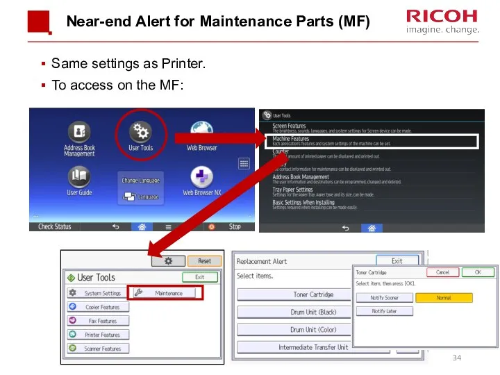
Near-end Alert for Maintenance Parts (MF)
Same settings as Printer.
To access on
Near-end Alert for Maintenance Parts (MF)
Same settings as Printer.
To access on
What Happens at the End Alert?
For toner cartridges and the waste
What Happens at the End Alert?
For toner cartridges and the waste
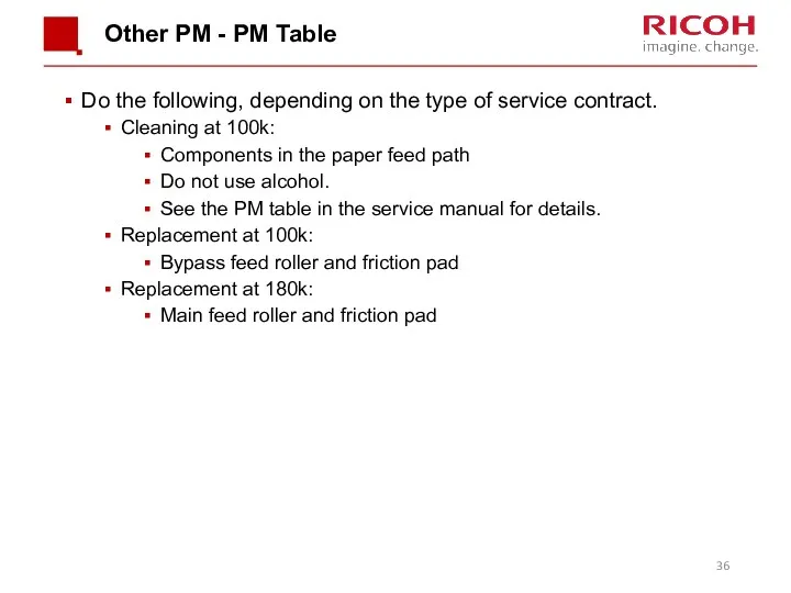
Other PM - PM Table
Do the following, depending on the type
Other PM - PM Table
Do the following, depending on the type
Updating Firmware
The procedure uses SD cards and is the same as
Updating Firmware
The procedure uses SD cards and is the same as

3. Detailed Section Descriptions
3. Detailed Section Descriptions

Machine Overview
Machine Overview
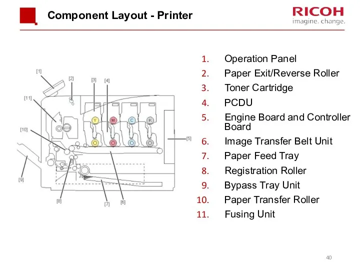
Component Layout - Printer
Operation Panel
Paper Exit/Reverse Roller
Toner Cartridge
PCDU
Engine Board and Controller
Component Layout - Printer
Operation Panel
Paper Exit/Reverse Roller
Toner Cartridge
PCDU
Engine Board and Controller
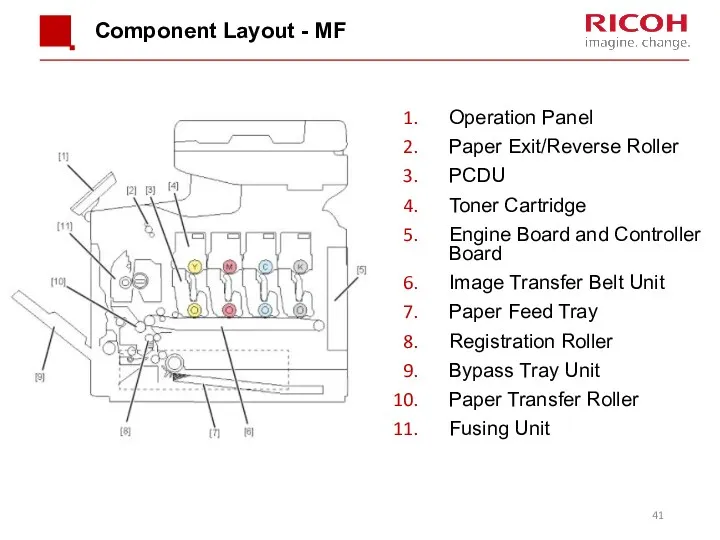
Component Layout - MF
Operation Panel
Paper Exit/Reverse Roller
PCDU
Toner Cartridge
Engine Board and Controller
Component Layout - MF
Operation Panel
Paper Exit/Reverse Roller
PCDU
Toner Cartridge
Engine Board and Controller
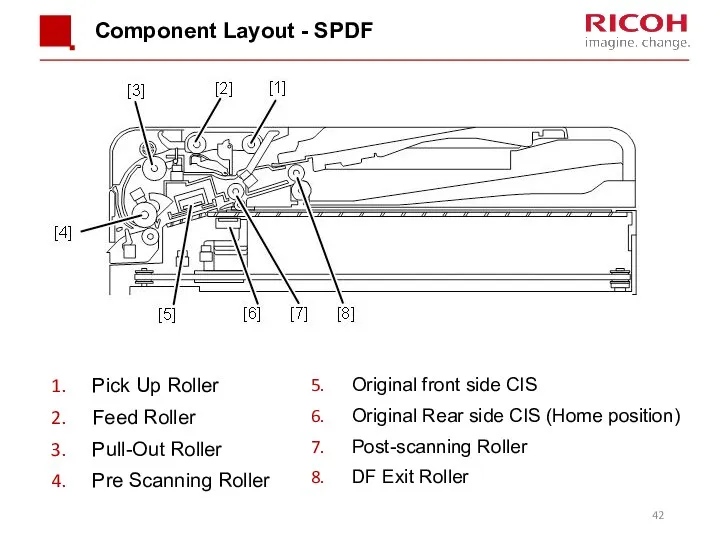
Component Layout - SPDF
Pick Up Roller
Feed Roller
Pull-Out Roller
Pre Scanning Roller
Original front
Component Layout - SPDF
Pick Up Roller
Feed Roller
Pull-Out Roller
Pre Scanning Roller
Original front
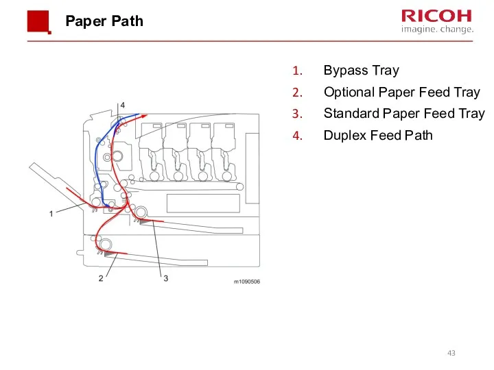
Paper Path
Bypass Tray
Optional Paper Feed Tray
Standard Paper Feed Tray
Duplex Feed Path
Paper Path
Bypass Tray
Optional Paper Feed Tray
Standard Paper Feed Tray
Duplex Feed Path
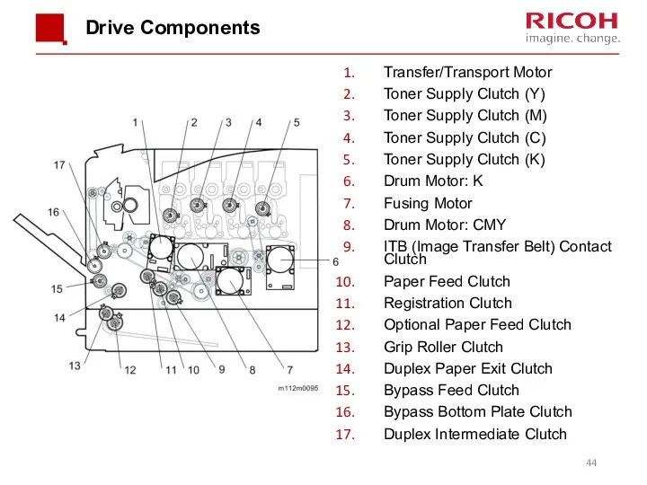
Drive Components
Transfer/Transport Motor
Toner Supply Clutch (Y)
Toner Supply Clutch (M)
Toner Supply Clutch
Drive Components
Transfer/Transport Motor
Toner Supply Clutch (Y)
Toner Supply Clutch (M)
Toner Supply Clutch
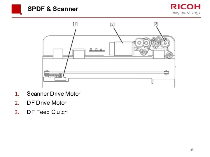
Scanner Drive Motor
DF Drive Motor
DF Feed Clutch
SPDF & Scanner
Scanner Drive Motor
DF Drive Motor
DF Feed Clutch
SPDF & Scanner
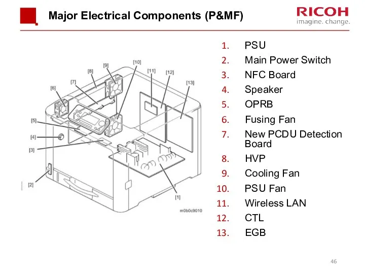
Major Electrical Components (P&MF)
PSU
Main Power Switch
NFC Board
Speaker
OPRB
Fusing Fan
New PCDU Detection
Major Electrical Components (P&MF)
PSU
Main Power Switch
NFC Board
Speaker
OPRB
Fusing Fan
New PCDU Detection
Main Circuit Boards
EGB (Engine Board): Controls the engine, the controller interface,
Main Circuit Boards
EGB (Engine Board): Controls the engine, the controller interface,
Before Servicing the Machine
Before you start to remove parts from the
Before Servicing the Machine
Before you start to remove parts from the
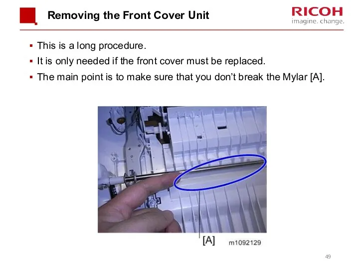
Removing the Front Cover Unit
This is a long procedure.
It is only
Removing the Front Cover Unit
This is a long procedure.
It is only
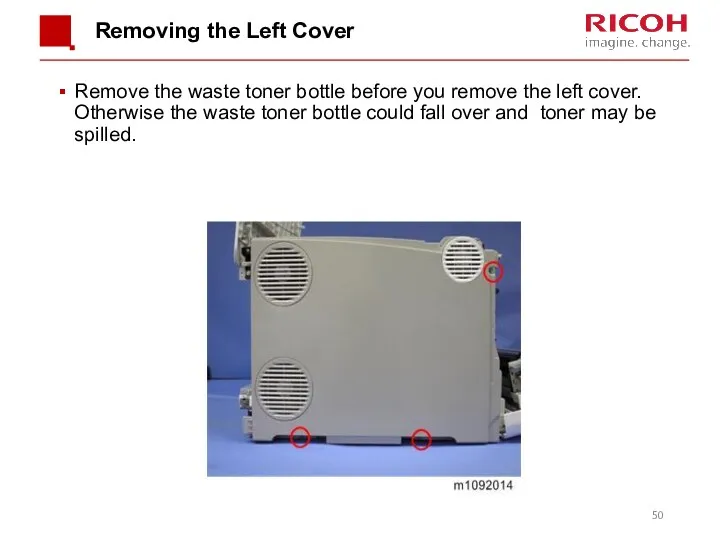
Removing the Left Cover
Remove the waste toner bottle before you remove
Removing the Left Cover
Remove the waste toner bottle before you remove
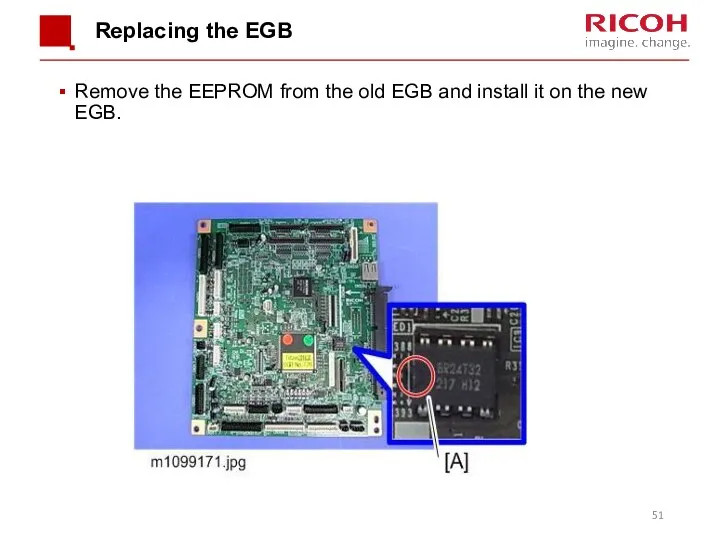
Replacing the EGB
Remove the EEPROM from the old EGB and install
Replacing the EGB
Remove the EEPROM from the old EGB and install
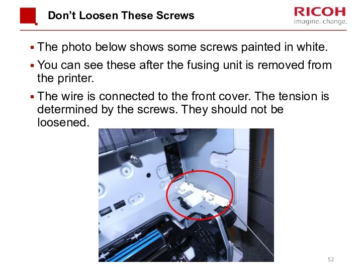
Don’t Loosen These Screws
The photo below shows some screws painted in
Don’t Loosen These Screws
The photo below shows some screws painted in
Replacing EEPROM on the EGB (1/2)
When replacing the EEPROM on the
Replacing EEPROM on the EGB (1/2)
When replacing the EEPROM on the
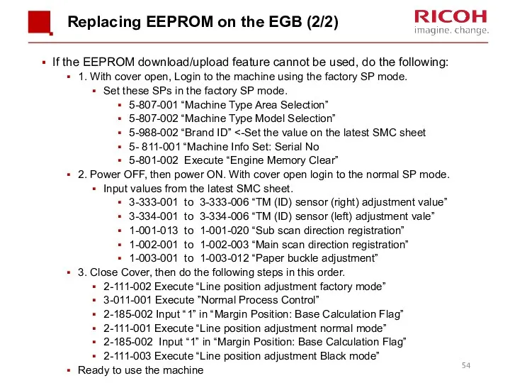
Replacing EEPROM on the EGB (2/2)
If the EEPROM download/upload feature cannot
Replacing EEPROM on the EGB (2/2)
If the EEPROM download/upload feature cannot
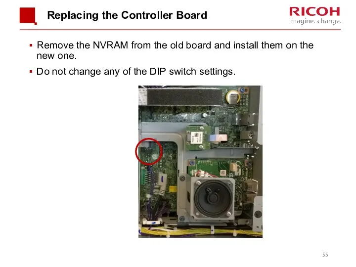
Replacing the Controller Board
Remove the NVRAM from the old board and
Replacing the Controller Board
Remove the NVRAM from the old board and

Image Creation
Image Creation
![Overview An LED array [1] writes the latent image on](/_ipx/f_webp&q_80&fit_contain&s_1440x1080/imagesDir/jpg/341418/slide-56.jpg)
Overview
An LED array [1] writes the latent image on the OPC
Overview
An LED array [1] writes the latent image on the OPC
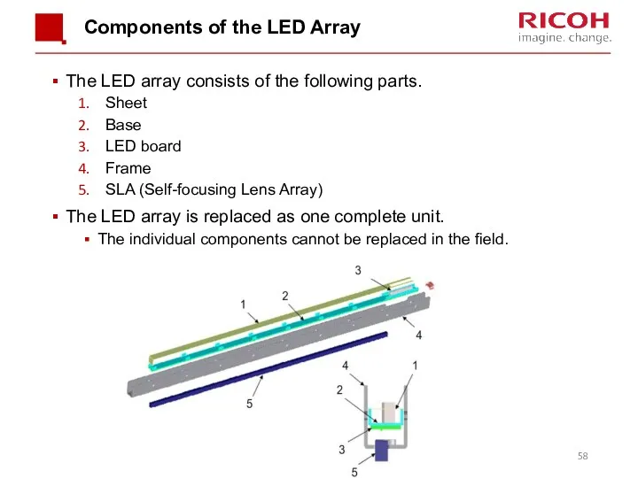
Components of the LED Array
The LED array consists of the following
Components of the LED Array
The LED array consists of the following
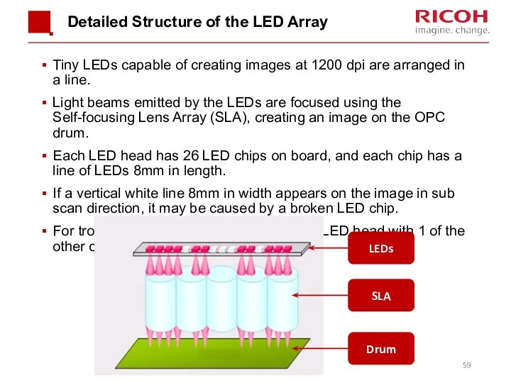
Detailed Structure of the LED Array
Tiny LEDs capable of creating images
Detailed Structure of the LED Array
Tiny LEDs capable of creating images
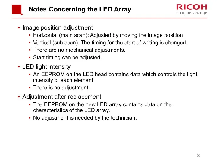
Notes Concerning the LED Array
Image position adjustment
Horizontal (main scan): Adjusted by
Notes Concerning the LED Array
Image position adjustment
Horizontal (main scan): Adjusted by
Troubleshooting Notes
The LED heads are the same for all CMYK colors.
So
Troubleshooting Notes
The LED heads are the same for all CMYK colors.
So
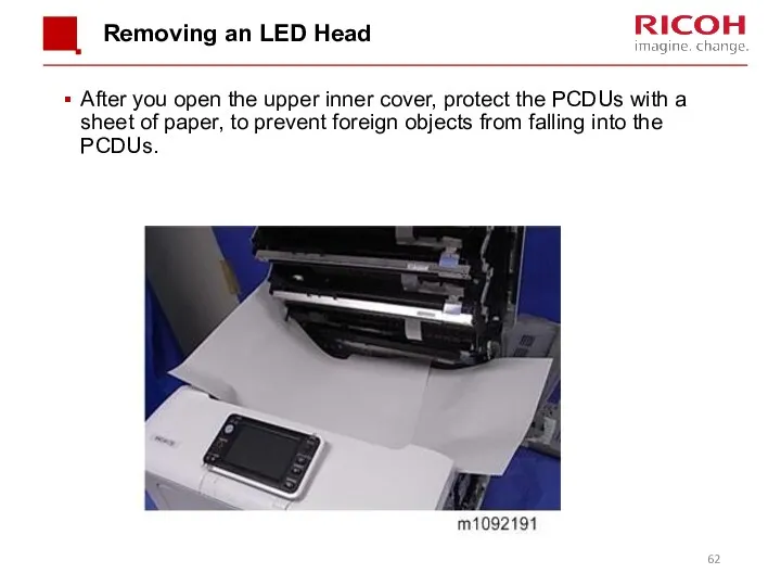
Removing an LED Head
After you open the upper inner cover, protect
Removing an LED Head
After you open the upper inner cover, protect
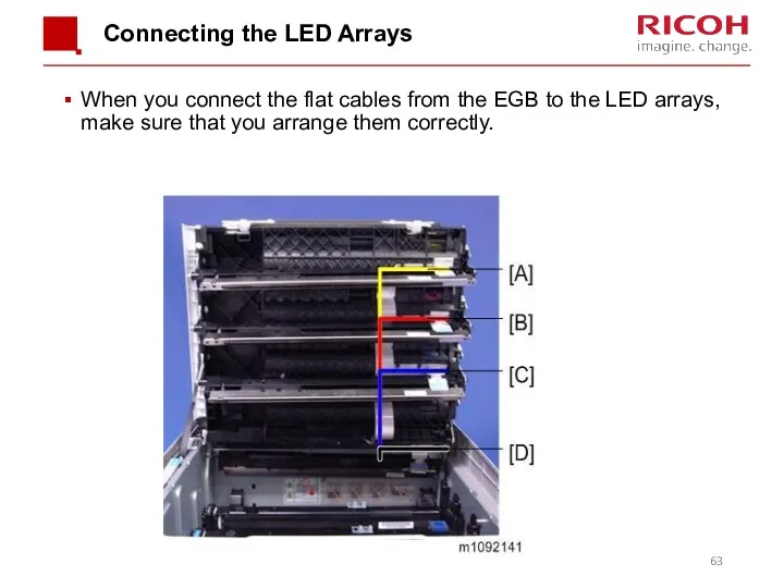
Connecting the LED Arrays
When you connect the flat cables from the
Connecting the LED Arrays
When you connect the flat cables from the
Toner Cartridge and PCDU
Toner Cartridge and PCDU
Toner Cartridges
Each toner cartridge contains the toner bottle and toner supply
Toner Cartridges
Each toner cartridge contains the toner bottle and toner supply
Shutters
Each cartridge has two shutters.
Toner will not leave the cartridge
Shutters
Each cartridge has two shutters.
Toner will not leave the cartridge
Toner Supply Solenoid & Shutter
If you have to remove the solenoid
Toner Supply Solenoid & Shutter
If you have to remove the solenoid
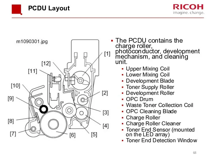
PCDU Layout
The PCDU contains the charge roller, photoconductor, development mechanism, and
PCDU Layout
The PCDU contains the charge roller, photoconductor, development mechanism, and
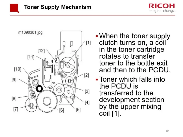
Toner Supply Mechanism
When the toner supply clutch turns on, a coil
Toner Supply Mechanism
When the toner supply clutch turns on, a coil
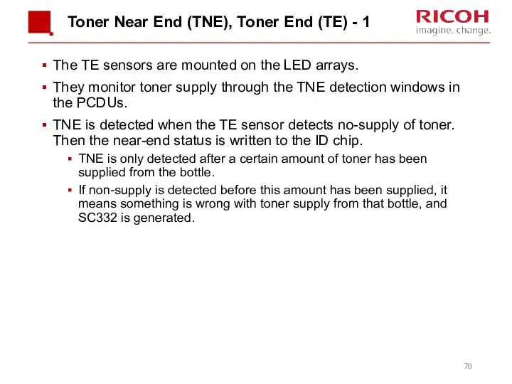
Toner Near End (TNE), Toner End (TE) - 1
The TE sensors
Toner Near End (TNE), Toner End (TE) - 1
The TE sensors
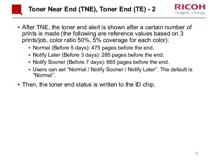
Toner Near End (TNE), Toner End (TE) - 2
After TNE, the
Toner Near End (TNE), Toner End (TE) - 2
After TNE, the
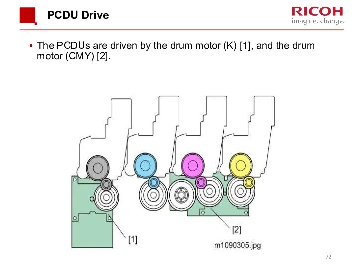
PCDU Drive
The PCDUs are driven by the drum motor (K) [1],
PCDU Drive
The PCDUs are driven by the drum motor (K) [1],
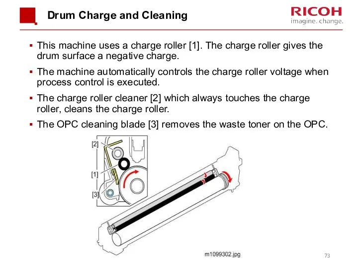
Drum Charge and Cleaning
This machine uses a charge roller [1]. The
Drum Charge and Cleaning
This machine uses a charge roller [1]. The
![Development The development mechanism contains the development roller [1], the](/_ipx/f_webp&q_80&fit_contain&s_1440x1080/imagesDir/jpg/341418/slide-73.jpg)
Development
The development mechanism contains the development roller [1], the toner supply
Development
The development mechanism contains the development roller [1], the toner supply
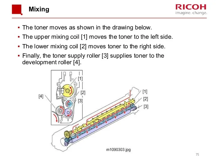
Mixing
The toner moves as shown in the drawing below.
The upper
Mixing
The toner moves as shown in the drawing below.
The upper
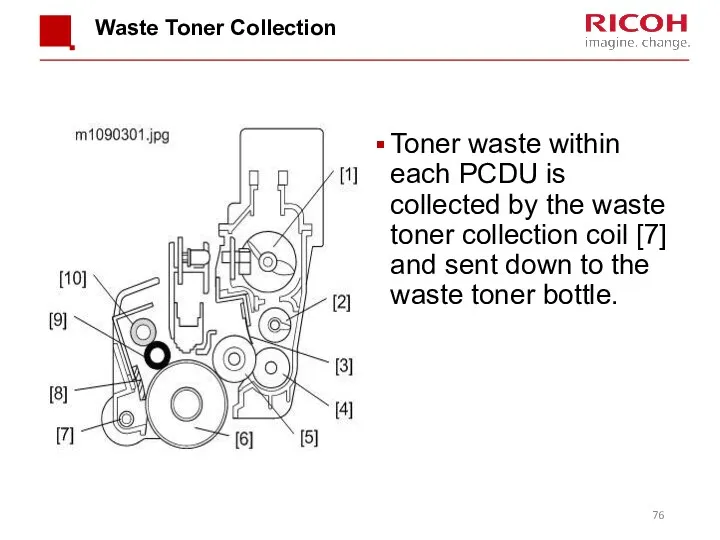
Waste Toner Collection
Toner waste within each PCDU is collected by the
Waste Toner Collection
Toner waste within each PCDU is collected by the
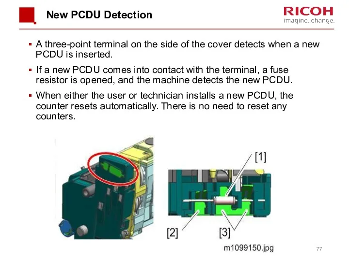
New PCDU Detection
A three-point terminal on the side of the cover
New PCDU Detection
A three-point terminal on the side of the cover
Replacing the Toner End Sensor
The toner end sensor is built into
Replacing the Toner End Sensor
The toner end sensor is built into

Paper Feed
Paper Feed
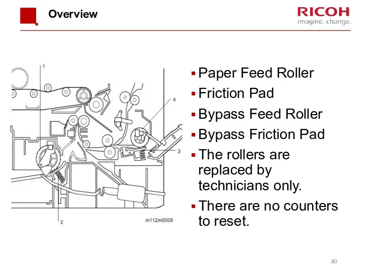
Overview
Paper Feed Roller
Friction Pad
Bypass Feed Roller
Bypass Friction Pad
The rollers are
Overview
Paper Feed Roller
Friction Pad
Bypass Feed Roller
Bypass Friction Pad
The rollers are
Drive
For paper feed, the machine turns on the paper feed clutch,
Drive
For paper feed, the machine turns on the paper feed clutch,
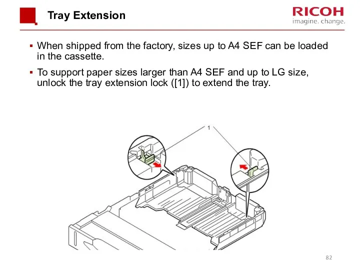
Tray Extension
When shipped from the factory, sizes up to A4 SEF
Tray Extension
When shipped from the factory, sizes up to A4 SEF
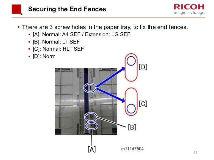
Securing the End Fences
There are 3 screw holes in the paper
Securing the End Fences
There are 3 screw holes in the paper
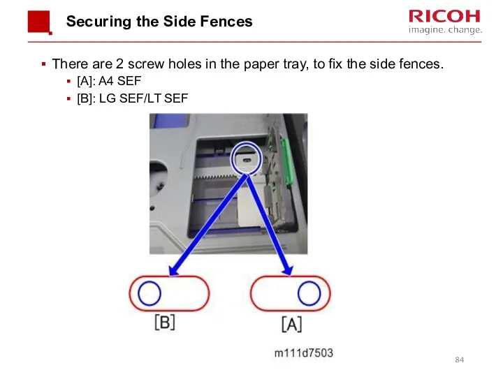
Securing the Side Fences
There are 2 screw holes in the paper
Securing the Side Fences
There are 2 screw holes in the paper
![Paper Size Detection The paper size switch [2] detects actuators](/_ipx/f_webp&q_80&fit_contain&s_1440x1080/imagesDir/jpg/341418/slide-84.jpg)
Paper Size Detection
The paper size switch [2] detects actuators attached to
Paper Size Detection
The paper size switch [2] detects actuators attached to
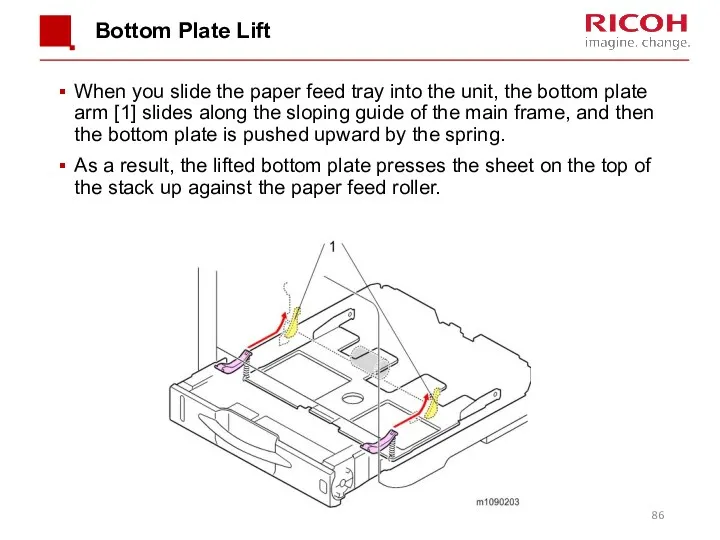
Bottom Plate Lift
When you slide the paper feed tray into the
Bottom Plate Lift
When you slide the paper feed tray into the
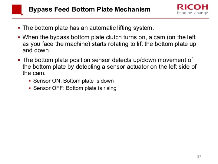
Bypass Feed Bottom Plate Mechanism
The bottom plate has an automatic lifting
Bypass Feed Bottom Plate Mechanism
The bottom plate has an automatic lifting
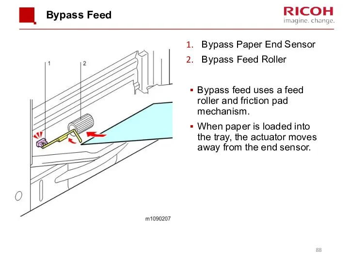
Bypass Feed
Bypass Paper End Sensor
Bypass Feed Roller
Bypass feed uses a
Bypass Feed
Bypass Paper End Sensor
Bypass Feed Roller
Bypass feed uses a
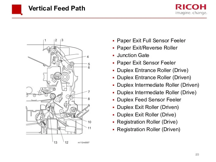
Vertical Feed Path
Paper Exit Full Sensor Feeler
Paper Exit/Reverse Roller
Junction Gate
Paper Exit
Vertical Feed Path
Paper Exit Full Sensor Feeler
Paper Exit/Reverse Roller
Junction Gate
Paper Exit
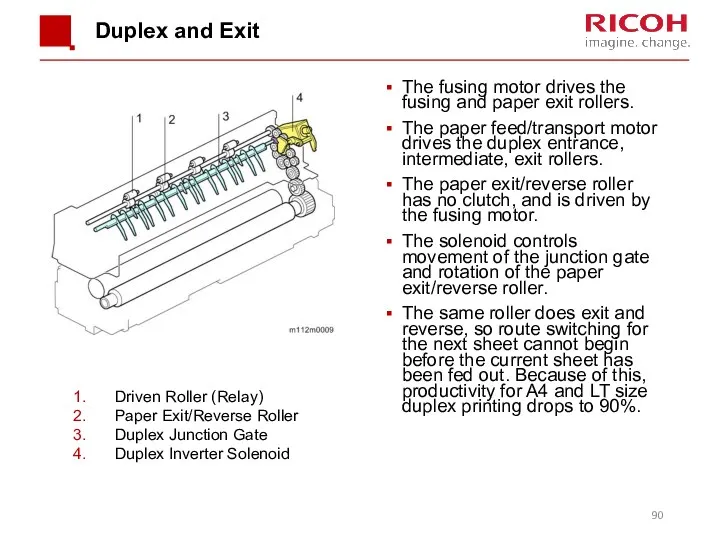
Duplex and Exit
The fusing motor drives the fusing and paper exit
Duplex and Exit
The fusing motor drives the fusing and paper exit
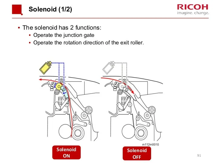
Solenoid (1/2)
The solenoid has 2 functions:
Operate the junction gate
Operate the rotation
Solenoid (1/2)
The solenoid has 2 functions:
Operate the junction gate
Operate the rotation
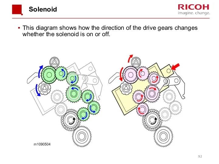
Solenoid
This diagram shows how the direction of the drive gears changes
Solenoid
This diagram shows how the direction of the drive gears changes

Image Transfer
Image Transfer
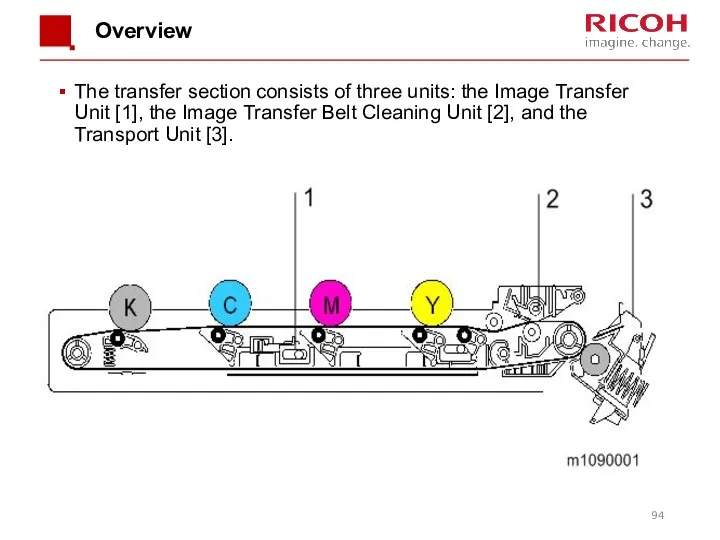
Overview
The transfer section consists of three units: the Image Transfer Unit
Overview
The transfer section consists of three units: the Image Transfer Unit
![Image Transfer Belt Unit The transfer/transport motor [2] drives the](/_ipx/f_webp&q_80&fit_contain&s_1440x1080/imagesDir/jpg/341418/slide-94.jpg)
Image Transfer Belt Unit
The transfer/transport motor [2] drives the ITB drive
Image Transfer Belt Unit
The transfer/transport motor [2] drives the ITB drive
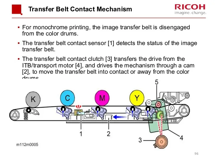
Transfer Belt Contact Mechanism
For monochrome printing, the image transfer belt is
Transfer Belt Contact Mechanism
For monochrome printing, the image transfer belt is
![Belt Guide Roller In previous models, this roller [5] was](/_ipx/f_webp&q_80&fit_contain&s_1440x1080/imagesDir/jpg/341418/slide-96.jpg)
Belt Guide Roller
In previous models, this roller [5] was inside the
Belt Guide Roller
In previous models, this roller [5] was inside the
![Transfer Belt Cleaning The transfer cleaning blade [1] removes remaining](/_ipx/f_webp&q_80&fit_contain&s_1440x1080/imagesDir/jpg/341418/slide-97.jpg)
Transfer Belt Cleaning
The transfer cleaning blade [1] removes remaining toner from
Transfer Belt Cleaning
The transfer cleaning blade [1] removes remaining toner from
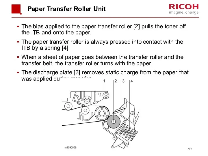
Paper Transfer Roller Unit
The bias applied to the paper transfer roller
Paper Transfer Roller Unit
The bias applied to the paper transfer roller
Transfer Roller Cleaning
Toner may transfer to the roller surface following a
Transfer Roller Cleaning
Toner may transfer to the roller surface following a
![Paper Separation During paper transfer, the transfer roller [A] applies](/_ipx/f_webp&q_80&fit_contain&s_1440x1080/imagesDir/jpg/341418/slide-100.jpg)
Paper Separation
During paper transfer, the transfer roller [A] applies a static
Paper Separation
During paper transfer, the transfer roller [A] applies a static
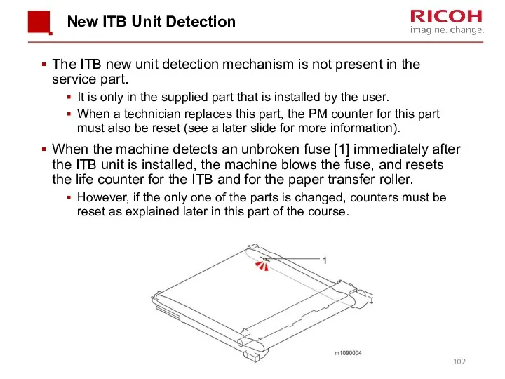
New ITB Unit Detection
The ITB new unit detection mechanism is not
New ITB Unit Detection
The ITB new unit detection mechanism is not
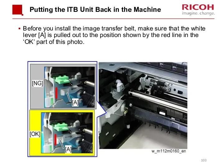
Putting the ITB Unit Back in the Machine
Before you install the
Putting the ITB Unit Back in the Machine
Before you install the
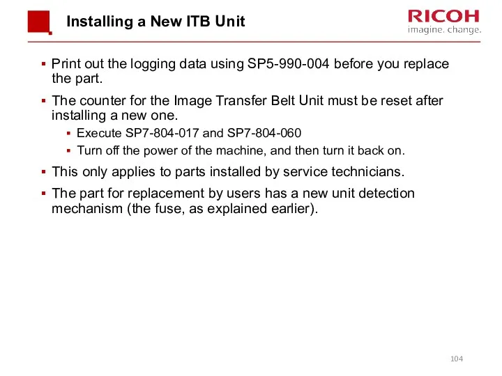
Installing a New ITB Unit
Print out the logging data using SP5-990-004
Installing a New ITB Unit
Print out the logging data using SP5-990-004
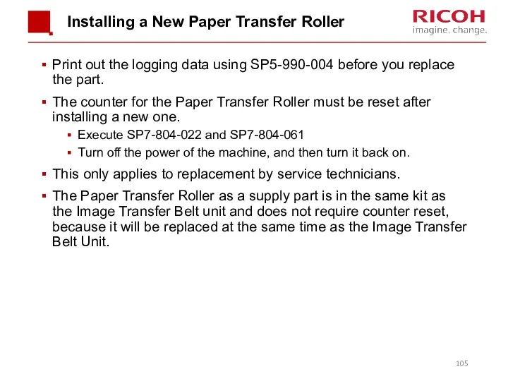
Installing a New Paper Transfer Roller
Print out the logging data using
Installing a New Paper Transfer Roller
Print out the logging data using
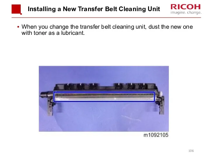
Installing a New Transfer Belt Cleaning Unit
When you change the transfer
Installing a New Transfer Belt Cleaning Unit
When you change the transfer
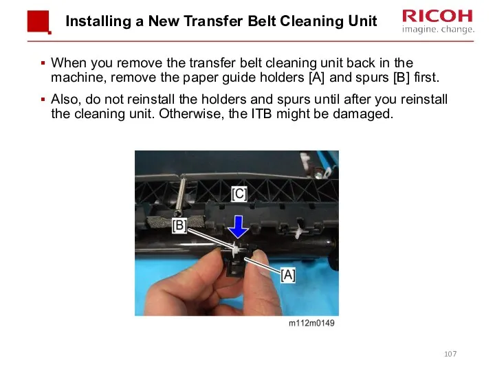
Installing a New Transfer Belt Cleaning Unit
When you remove the transfer
Installing a New Transfer Belt Cleaning Unit
When you remove the transfer

Fusing
Fusing
Overview
This machine uses a QSU (Quick Start Up) type of fusing
Overview
This machine uses a QSU (Quick Start Up) type of fusing
Quick Start-up (QSU) System
1. Heating Pipe
Conducts heat from the fusing lamps
Quick Start-up (QSU) System
1. Heating Pipe
Conducts heat from the fusing lamps
![Fusing Unit Drive The fusing motor [1] drives the pressure](/_ipx/f_webp&q_80&fit_contain&s_1440x1080/imagesDir/jpg/341418/slide-110.jpg)
Fusing Unit Drive
The fusing motor [1] drives the pressure roller [2],
Fusing Unit Drive
The fusing motor [1] drives the pressure roller [2],
![New Unit Detection This is done using a fuse [2]](/_ipx/f_webp&q_80&fit_contain&s_1440x1080/imagesDir/jpg/341418/slide-111.jpg)
New Unit Detection
This is done using a fuse [2] on the
New Unit Detection
This is done using a fuse [2] on the

Pressure Release
A pressure release mechanism makes it easy to remove paper
Pressure Release
A pressure release mechanism makes it easy to remove paper
![Fusing Temperature Control A thermostat [3] and a non-contact thermistor](/_ipx/f_webp&q_80&fit_contain&s_1440x1080/imagesDir/jpg/341418/slide-113.jpg)
Fusing Temperature Control
A thermostat [3] and a non-contact thermistor [1] monitor
Fusing Temperature Control
A thermostat [3] and a non-contact thermistor [1] monitor
Fusing Temperature Control
Warming-up Mode
Fusing warm-up begins after the machine power is
Fusing Temperature Control
Warming-up Mode
Fusing warm-up begins after the machine power is
Fusing Temperature Control
Print Mode
The fusing temperature increases to the “print ready
Fusing Temperature Control
Print Mode
The fusing temperature increases to the “print ready
Fusing Temperature Control
Wait Mode
The fusing lamp and the fusing motor turn
Fusing Temperature Control
Wait Mode
The fusing lamp and the fusing motor turn
Fusing Temperature Control
PPM Down Mode
PPM down control changes the feed timing
Fusing Temperature Control
PPM Down Mode
PPM down control changes the feed timing

Waste Toner Collection
Waste Toner Collection
Overview
Toner waste from the PCDUs is carried to the waste toner
Overview
Toner waste from the PCDUs is carried to the waste toner
![Drive The ITB waste toner collection coil [2] is driven](/_ipx/f_webp&q_80&fit_contain&s_1440x1080/imagesDir/jpg/341418/slide-120.jpg)
Drive
The ITB waste toner collection coil [2] is driven via the
Drive
The ITB waste toner collection coil [2] is driven via the
Waste Toner Bottle Set Sensor (1/2)
The waste toner bottle set sensor
Waste Toner Bottle Set Sensor (1/2)
The waste toner bottle set sensor
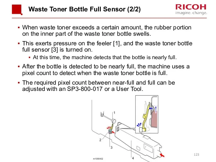
Waste Toner Bottle Full Sensor (2/2)
When waste toner exceeds a certain
Waste Toner Bottle Full Sensor (2/2)
When waste toner exceeds a certain
Toner Bottle Full
The pixel count corresponds to a number of sheets
Toner Bottle Full
The pixel count corresponds to a number of sheets
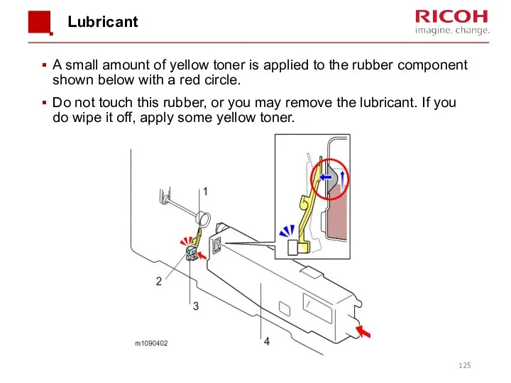
Lubricant
A small amount of yellow toner is applied to the rubber
Lubricant
A small amount of yellow toner is applied to the rubber
Replacement
Either the customer or the technician can replace the toner collection
Replacement
Either the customer or the technician can replace the toner collection

Process Control
Process Control
Processes
Process control
Development bias control
Toner supply control
MUSIC
The toner mark sensors (TM (ID)
Processes
Process control
Development bias control
Toner supply control
MUSIC
The toner mark sensors (TM (ID)
TM (ID) Sensors
Below the image transfer belt, there are two TM
TM (ID) Sensors
Below the image transfer belt, there are two TM
Replacing the TM (ID) Sensors (1/3)
Note that the sensor seen on
Replacing the TM (ID) Sensors (1/3)
Note that the sensor seen on
Replacing the TM (ID) Sensors (2/3)
Before replacement:
Each sensor has a label
Replacing the TM (ID) Sensors (2/3)
Before replacement:
Each sensor has a label
Replacing the TM (ID) Sensors (3/3)
After replacement:
Execute SP3-011-004 (Adjustment manual exe.
Replacing the TM (ID) Sensors (3/3)
After replacement:
Execute SP3-011-004 (Adjustment manual exe.
Paper Exit
MF Model:
To prevent of a early Tray full detection, caused
Paper Exit
MF Model:
To prevent of a early Tray full detection, caused
 Всероссийское военно-патриотическое движение ЮНармия
 Коррекция нарушения лексико-грамматических конструкций у детей с ОНР
 Электрооборудование котельной с разработкой схемы управления резервного источника питания
 Лук - за обедом лучший друг!
 Презентация Дикие животные и их детеныши
 Презентация по теме: Сложение и вычитание десятичных дробей 5 класс.
 Классный час с презентацией Память бережно храним во 2 классе
 Как можно ускорить экономический рост.
 Мочекаменная болезнь: этиология и патогенез
 В поисках Неумейки
 Цемент. Свойства цемента
 Кільчасті черви
 Презентация Проблемы преемственности дошкольного и начального общего образования в условиях введения ФГОС
 Жаратылыстану 2 - сынып
 Совместный проект детей, воспитателя и родителей в старшей группе Промыслы нижегородкой области
 My favorite singer
 Системы отопления. Техническая презентация для проектных и обслуживающих организаций
 Инженерно-технические методы защиты объектов. Исследование эффективности централизованной и автономной систем безопасности
 Применение методов информатики для технологических расчетов в производстве целлюлозы
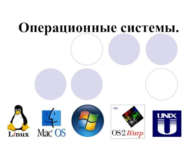 Операционные системы
 Проект Чистый город
 Новогодние и рождественские открытки в стиле различных художников
 Роль медицинской сестры в оказании паллиативной помощи
 Оборудование для погружения винтовых свай
 Витаминдер және оның маңызы
 Общие сведения по геодезии
 Презентация 14.06.22
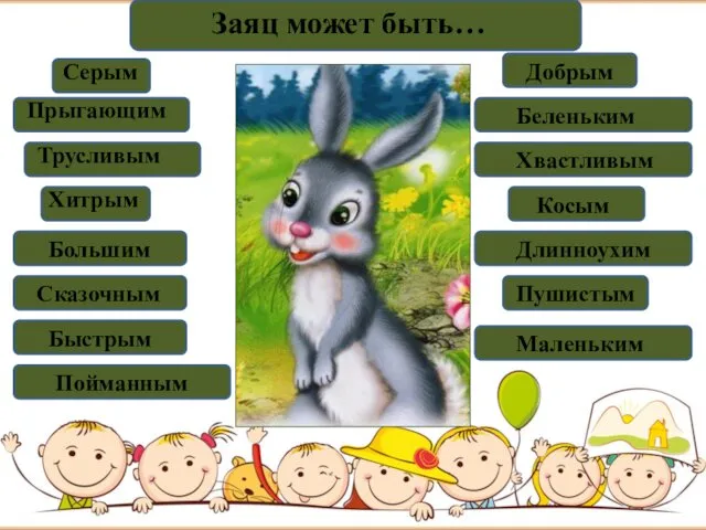 Заяц
Заяц