- Wooden structures of wooden structures by the method of limit states

Содержание
- 2. EN RK 1995-1-1: 2008/2011 Design of wooden structures. Section 1-1. General rules and building regulations); EN
- 3. Importance of wooden structures Wood is loved not only by architects, but also by craftsmen, technicians
- 4. Advantages of wooden structures: wood - lightweight material; wood is easily processed both at the
- 5. Disadvantages that limit the use of wooden structures: Swelling; drying; Danger of extinguishing and combustion; curvature;
- 6. Areas of application of wooden structures: Modern methods of wood preservation and gluing with waterproof adhesives
- 7. ADHESIVE CONSTRUCTIONS ARROW BACKS
- 8. ARCHES
- 9. FRAMEWORK STRUCTURES
- 10. DOME COVER
- 11. Design and calculation of elements of structures
- 12. Figure 1. Structural schemes and assemblies of two-story wooden roofs: a, b - suspended rafters (trusses)
- 13. The use of wooden structures is limited: - in multi-storey industrial buildings with large crane loads,
- 14. Wood structure In temperate climates, trees grow by increasing the concentration layers in the trunk. In
- 15. The light-colored inner strip is composed of flat-striped spring cells that form a low-strength young tree.
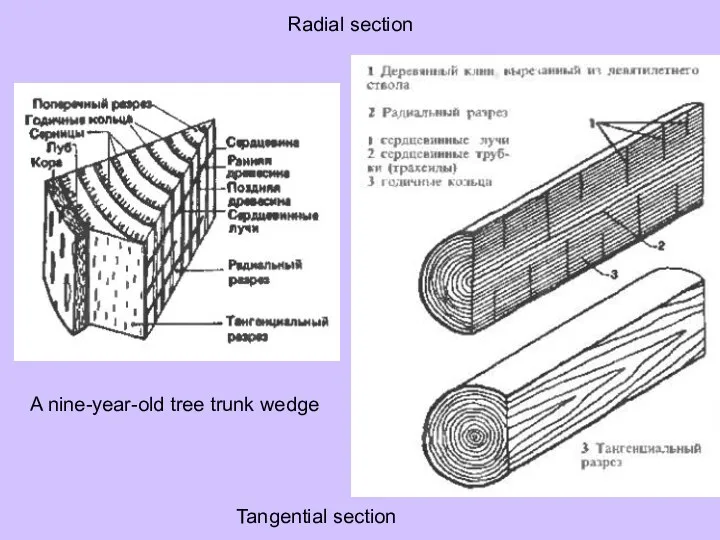
- 16. A nine-year-old tree trunk wedge Tangential section Radial section
- 17. Features that characterize the structure of wood: fiber and porosity. The structure of the tree is
- 18. Chemical composition of wood Cell membranes are composed mainly of cellulose, hemicellulose and lignin. As the
- 19. Physical properties of wood Wood has different properties in different directions, ie it belongs to anisotropic
- 20. Physical properties of wood Wood materials are divided into hard and soft wood materials according to
- 21. Physical properties of wood All wood materials are divided into strength classes according to the values
- 22. Mechanical properties of wood Strength and rigidity are the most important in building timber structures. The
- 23. Standard determination of the properties of wood is carried out in laboratories with the help of
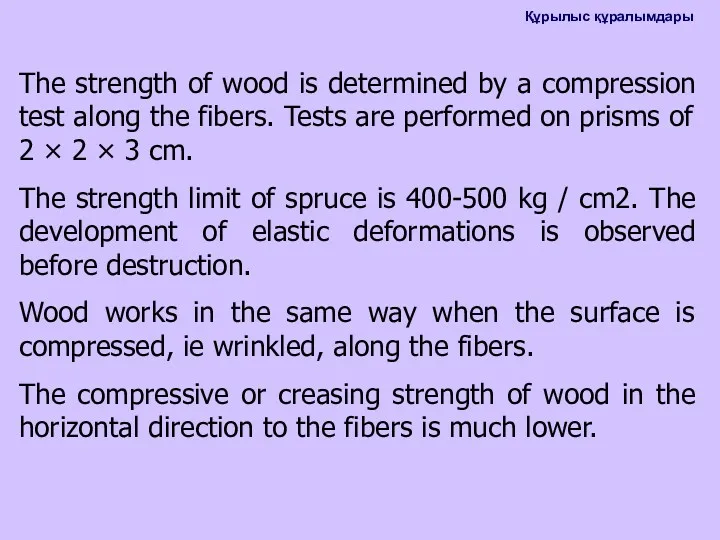
- 24. The strength of wood is determined by a compression test along the fibers. Tests are performed
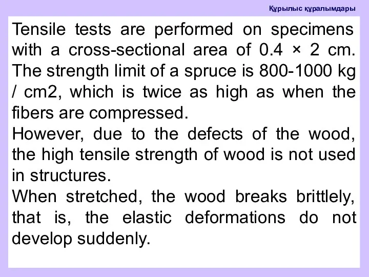
- 25. Tensile tests are performed on specimens with a cross-sectional area of 0.4 × 2 cm. The
- 26. Strength class. Characteristic values according to EN 338
- 27. Protection of wooden structures from rot Wood rot is a biochemical process that leads to collapse.
- 28. Materials The main materials of timber structures are cut materials made of pine and spruce in
- 29. Calculation of tree structures 2011 Characteristics of the introduced RK STD 05-01-1.1-2011 are as follows: Table
- 30. Elements extending from the middle Checks the strength of the elongated elements according to the following
- 31. ft, 0, d - the calculated resistance of wood to elongation along the fibers is determined
- 32. Table 25 Individual coefficient of material properties, fM
- 33. Table 26 - The value of the coefficient kmod
- 34. Compressed elements from the center Wood is well resistant to compression. The effect of wood defects
- 35. During axial loading, due to imperfections in the geometry of the element or changes in its
- 36. The calculated length of the element Le is determined: Le = μ0* L where L is
- 37. For a full-length idealized vertical element with homogeneous properties and two ends hinged, the critical force
- 38. Dividing A by the cross-sectional area of the corresponding critical strong element, we obtain the critical
- 39. Calculation for short and massive elements with relative flexibility λrel, y and λrel, z ≤ 0,3
- 40. For compressed elements with relative flexibility λrel, y> 0.3 and / or λrel, z> 0.3, the
- 41. fс, 0, d - the calculated resistance of the wood to compression along the fibers is
- 43. Скачать презентацию
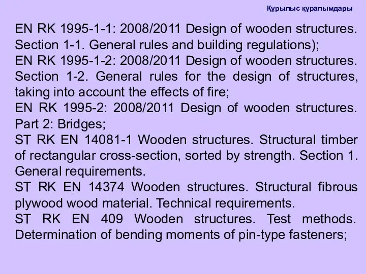
EN RK 1995-1-1: 2008/2011 Design of wooden structures. Section 1-1. General
EN RK 1995-1-1: 2008/2011 Design of wooden structures. Section 1-1. General
Importance of wooden structures
Wood is loved not only by architects, but
Importance of wooden structures
Wood is loved not only by architects, but
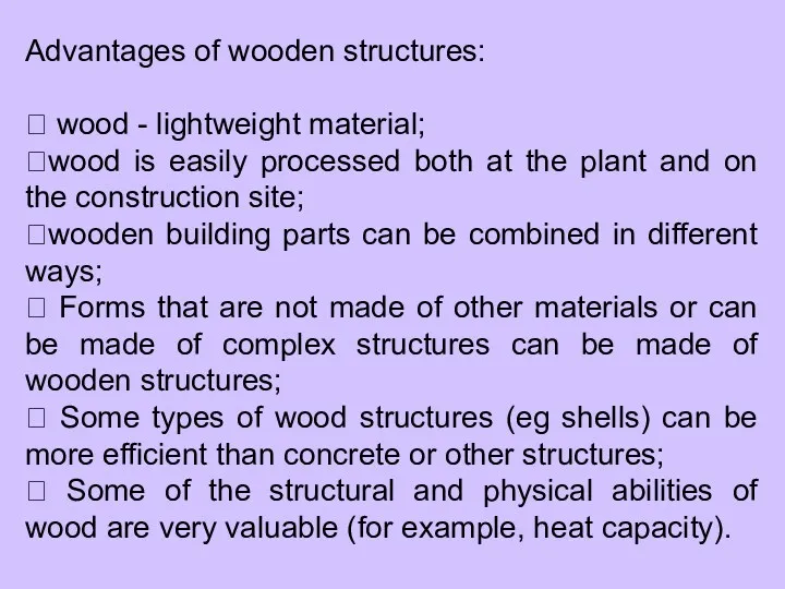
Advantages of wooden structures:
wood - lightweight material;
wood is easily processed
Advantages of wooden structures:
wood - lightweight material;
wood is easily processed
Disadvantages that limit the use of wooden structures:
Swelling;
drying;
Danger of extinguishing and
Disadvantages that limit the use of wooden structures:
Swelling;
drying;
Danger of extinguishing and
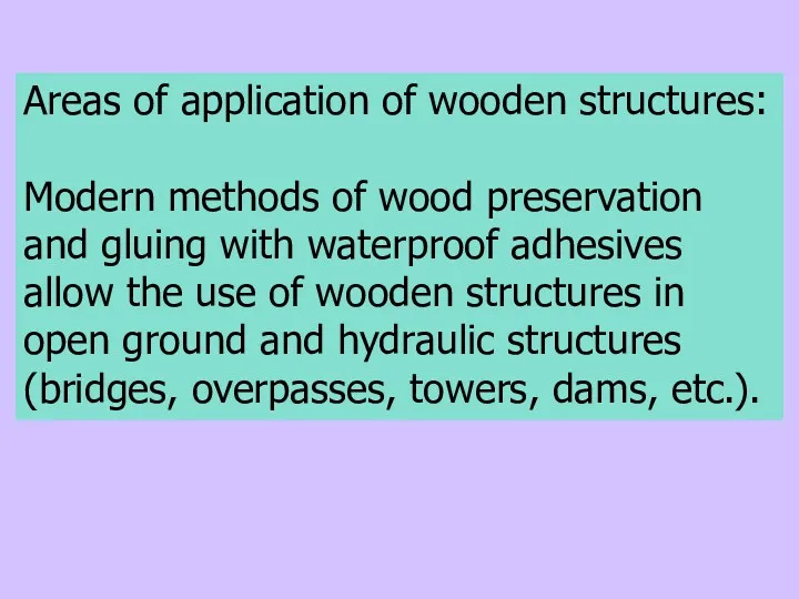
Areas of application of wooden structures:
Modern methods of wood preservation and
Areas of application of wooden structures:
Modern methods of wood preservation and
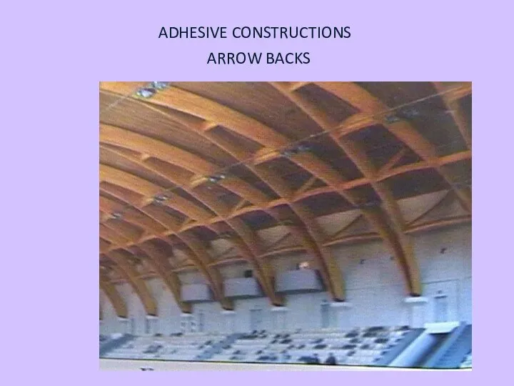
ADHESIVE CONSTRUCTIONS
ARROW BACKS
ADHESIVE CONSTRUCTIONS
ARROW BACKS
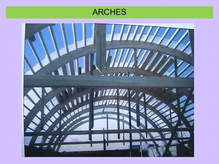
ARCHES
ARCHES

FRAMEWORK STRUCTURES
FRAMEWORK STRUCTURES

DOME COVER
DOME COVER
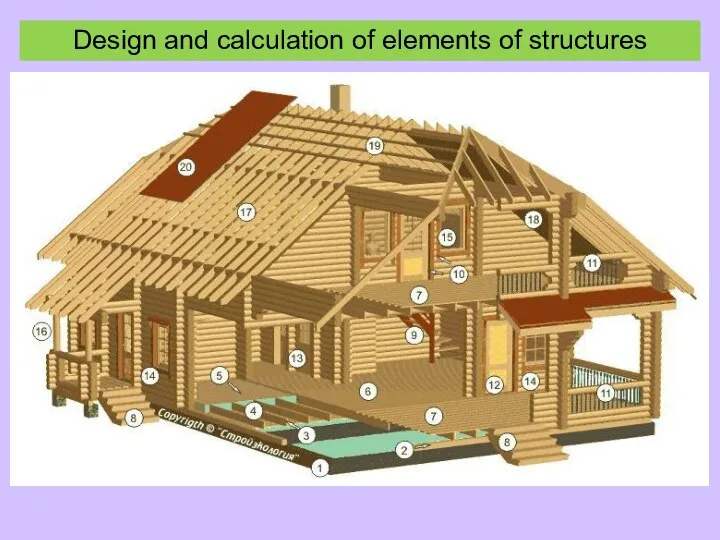
Design and calculation of elements of structures
Design and calculation of elements of structures
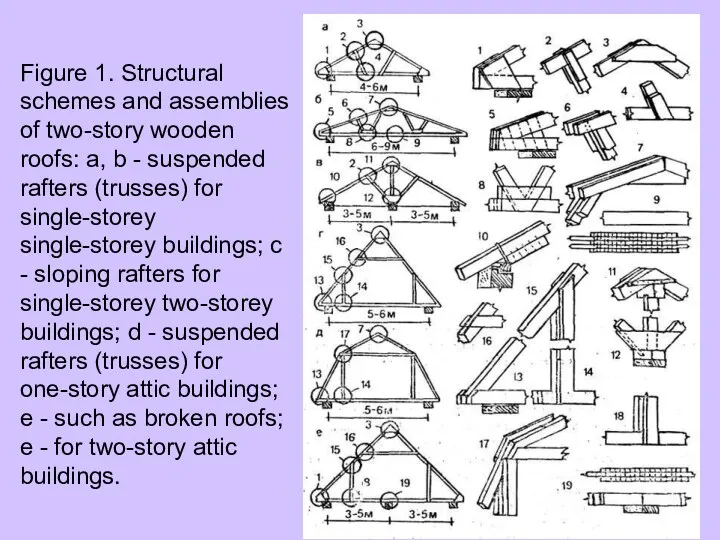
Figure 1. Structural schemes and assemblies of two-story wooden roofs: a,
Figure 1. Structural schemes and assemblies of two-story wooden roofs: a,
The use of wooden structures is limited:
- in multi-storey industrial buildings
The use of wooden structures is limited:
- in multi-storey industrial buildings
Wood structure
In temperate climates, trees grow by increasing the concentration layers
Wood structure
In temperate climates, trees grow by increasing the concentration layers
The light-colored inner strip is composed of flat-striped spring cells that
The light-colored inner strip is composed of flat-striped spring cells that
A nine-year-old tree trunk wedge
Tangential section
Radial section
A nine-year-old tree trunk wedge
Tangential section
Radial section
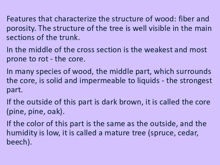
Features that characterize the structure of wood: fiber and porosity. The
Features that characterize the structure of wood: fiber and porosity. The
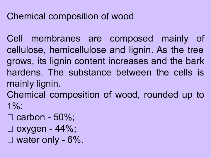
Chemical composition of wood
Cell membranes are composed mainly of cellulose, hemicellulose
Chemical composition of wood
Cell membranes are composed mainly of cellulose, hemicellulose
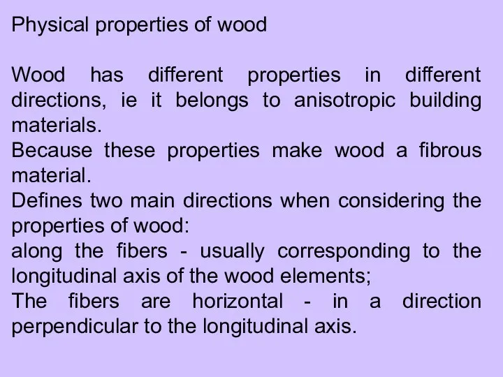
Physical properties of wood
Wood has different properties in different directions, ie
Physical properties of wood
Wood has different properties in different directions, ie
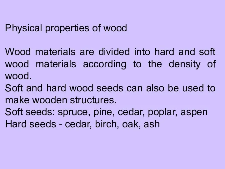
Physical properties of wood
Wood materials are divided into hard and soft
Physical properties of wood
Wood materials are divided into hard and soft
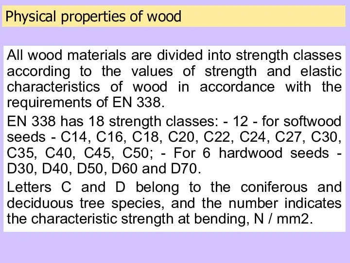
Physical properties of wood
All wood materials are divided into strength classes
Physical properties of wood
All wood materials are divided into strength classes
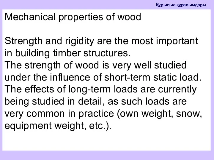
Mechanical properties of wood
Strength and rigidity are the most important in
Mechanical properties of wood
Strength and rigidity are the most important in
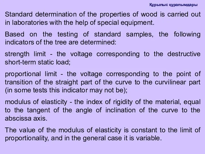
Standard determination of the properties of wood is carried out in
Standard determination of the properties of wood is carried out in
The strength of wood is determined by a compression test along
The strength of wood is determined by a compression test along
Tensile tests are performed on specimens with a cross-sectional area of
Tensile tests are performed on specimens with a cross-sectional area of
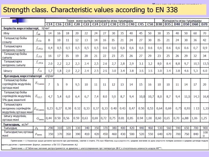
Strength class. Characteristic values according to EN 338
Strength class. Characteristic values according to EN 338
Protection of wooden structures from rot
Wood rot is a biochemical process
Protection of wooden structures from rot
Wood rot is a biochemical process
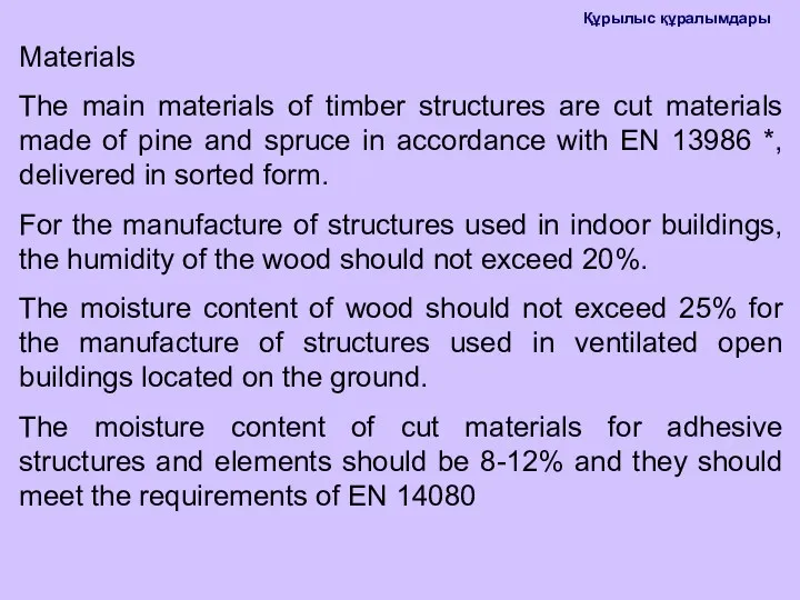
Materials
The main materials of timber structures are cut materials made of
Materials
The main materials of timber structures are cut materials made of
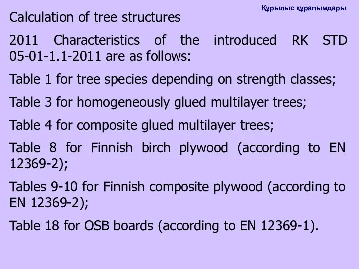
Calculation of tree structures
2011 Characteristics of the introduced RK STD 05-01-1.1-2011
Calculation of tree structures
2011 Characteristics of the introduced RK STD 05-01-1.1-2011
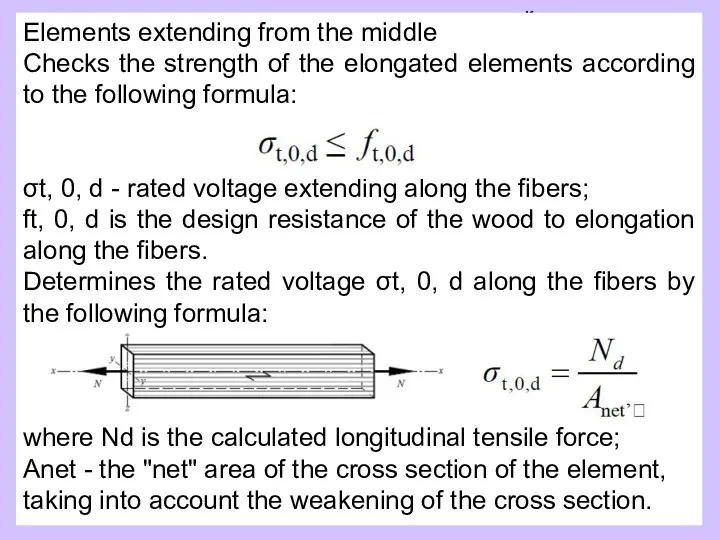
Elements extending from the middle
Checks the strength of the elongated elements
Elements extending from the middle
Checks the strength of the elongated elements
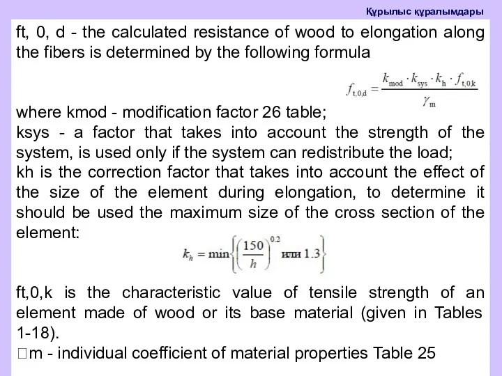
ft, 0, d - the calculated resistance of wood to elongation
ft, 0, d - the calculated resistance of wood to elongation
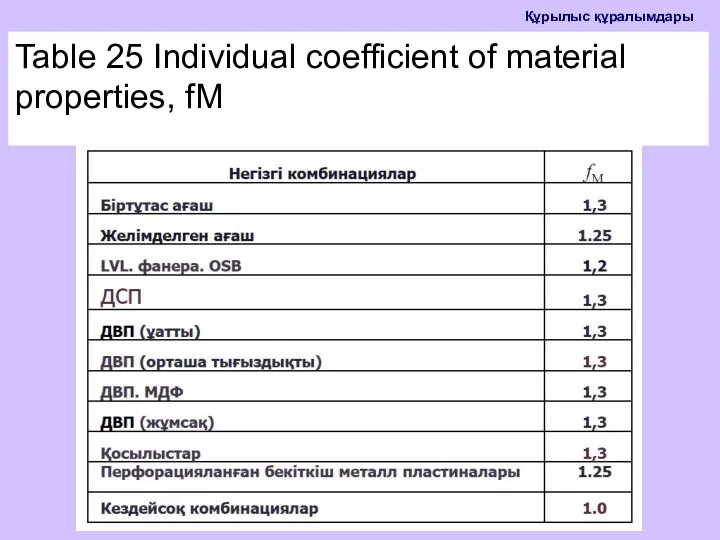
Table 25 Individual coefficient of material properties, fM
Table 25 Individual coefficient of material properties, fM
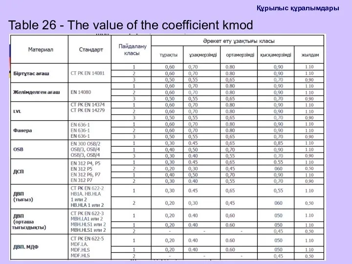
Table 26 - The value of the coefficient kmod
Table 26 - The value of the coefficient kmod
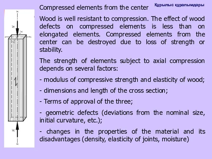
Compressed elements from the center
Wood is well resistant to compression. The
Compressed elements from the center
Wood is well resistant to compression. The
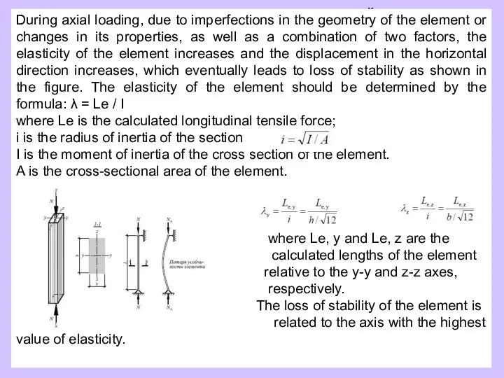
During axial loading, due to imperfections in the geometry of the
During axial loading, due to imperfections in the geometry of the
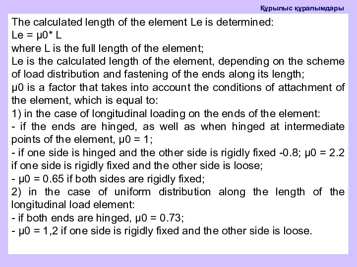
The calculated length of the element Le is determined:
Le = μ0*
The calculated length of the element Le is determined:
Le = μ0*
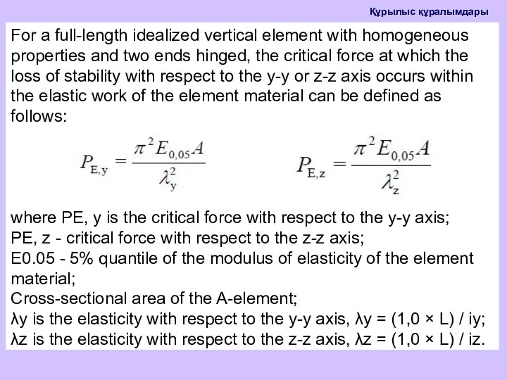
For a full-length idealized vertical element with homogeneous properties and two
For a full-length idealized vertical element with homogeneous properties and two
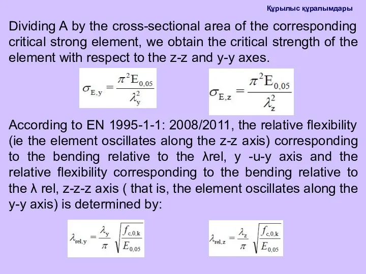
Dividing A by the cross-sectional area of the corresponding critical strong
Dividing A by the cross-sectional area of the corresponding critical strong
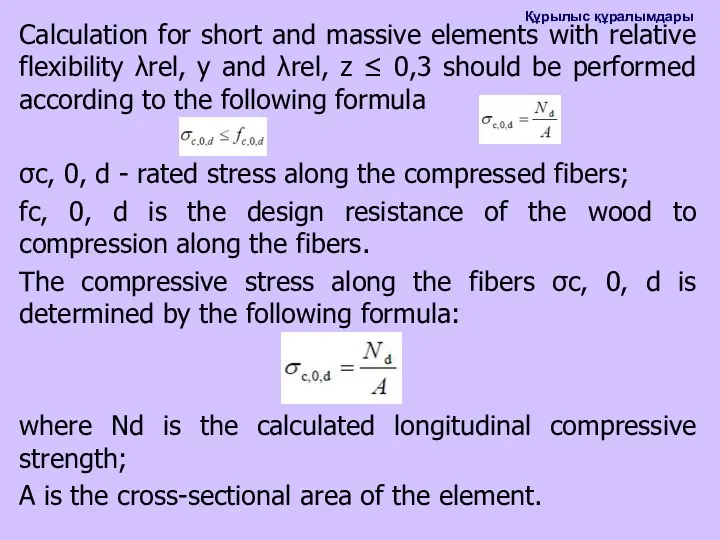
Calculation for short and massive elements with relative flexibility λrel, y
Calculation for short and massive elements with relative flexibility λrel, y
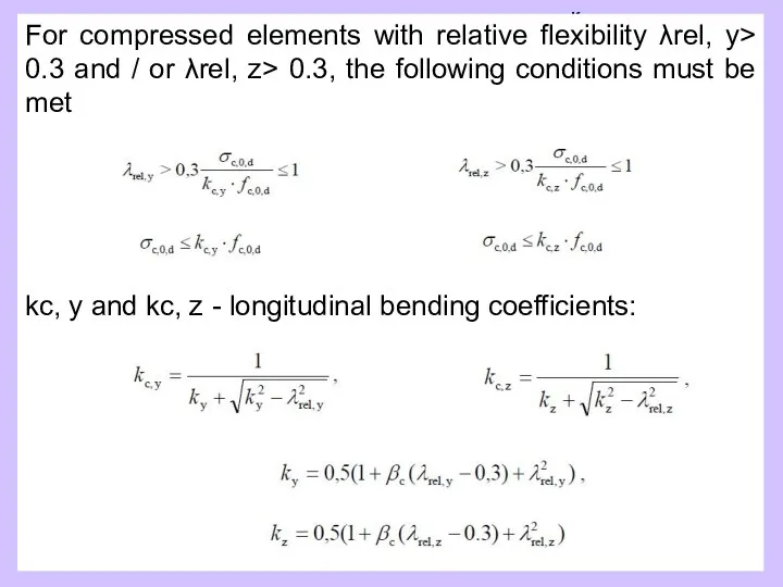
For compressed elements with relative flexibility λrel, y> 0.3 and /
For compressed elements with relative flexibility λrel, y> 0.3 and /
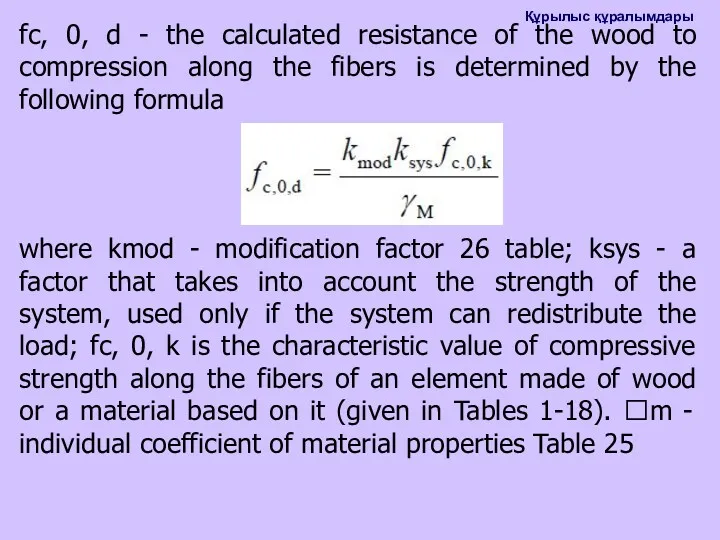
fс, 0, d - the calculated resistance of the wood to
fс, 0, d - the calculated resistance of the wood to
 Моя семья. Чулакова Найле
 Где же наши Парамоновичи? М.Ю.Лермонтов. 8 Б класс
 Патент № 2213311. Индукционная тигельная печь-термос
 Материя, движение, взаимодействие
 Музей-заповедник усадьба Абрамцево
 Балочная плита перекрытия, многопролетная неразрезная балка. Расчетная схема
 Базовые перинатальные матрицы Станислава Грофа
 Предмет органической химии
 Фенилхромановые соединения. Флавоноиды
 Российская империя в XVIII веке. Эпоха дворцовых переворотов 1725-1762
 Человек: информация и информационные процессы
 Копия татарское искусство
 Разминка перед тренировкой. Комплекс упражнений для подготовки тела к физической нагрузке
 Опоры ЛЭП
 Нормативно-правовое обеспечение деятельности временных детских разновозрастных коллективов
 Схема станции М
 Проектирование цифровых устройств на ПЛИС
 Технологические процессы заготовки кормов
 шаблон для презентаций Лотос и Яблоневый цвет
 Empirical Legal Research
 Электромеханические элементы релейной защиты
 Международные стандарты ISO серии 9000
 Цифровая схемотехника. Счетчики. (Лекция 11)
 Снятие мерок с фигуры человека
 Народная кукла-оберег. Травница.
 Учебно-методические комплексы (УМК) для начальной школы
 Русско-ордынские отношения
 Рекреационная география. Рекреация, как социально-экономическое явление. (Лекция 2)