- A4CFx – New Alpha. Power Train Variation Engine

Содержание
- 2. Power Train Variation (A4CFx) (M5CFx)
- 3. * In this material only New Alpha transmission will be introduced. Power Train Variation
- 4. * To distinguish Transmission, you can use stamping mark on top of transmission. Even same type
- 5. Main Components Reverse Clutch O/D Clutch Rear Cover 2nd Brake L/R & Reverse Brake Output Shaft
- 6. Comparison Specification
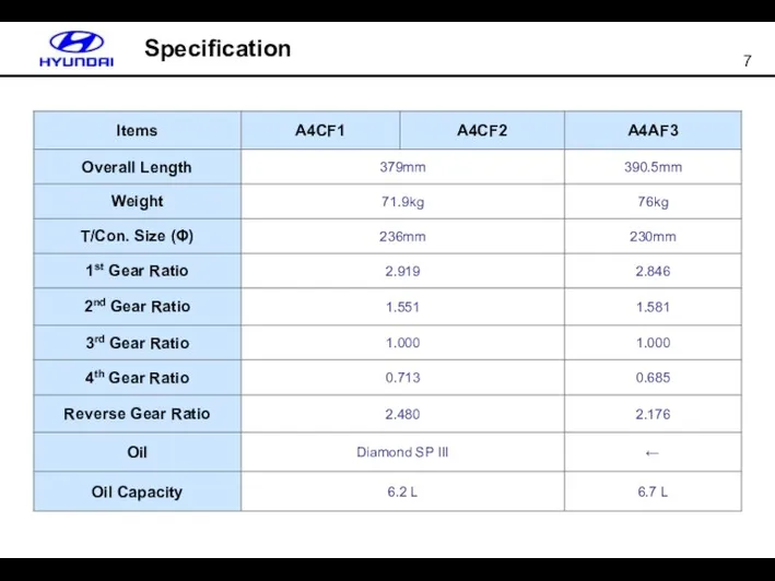
- 7. Comparison Specification
- 8. Main Features Long travel damper clutch Flat & Long Travel type torque converter Full line pressure
- 9. Oil Pump
- 10. Torque Converter Reducing Thickness by 5mm Adapting long travel damper spring
- 11. Disc Type Return Spring (L/R Brake) Disc Spring T F T
- 12. Reducing the supplying oil for differential gear Reducing friction loss by differential gear rotation Increasing lubrication
- 13. Valve Body Valve body and spool valve are from Alloy Full line pressure control Individual Clutch
- 14. PCSV - A : O/D or LR Solenoid PCSV - B : 2/4 or REV Solenoid
- 15. Accumulator Each Spring can be interchangeable except white one ⓑ ⓒ ⓓ ⓐ UD (two springs
- 16. Hydraulic Pressure Checking Port * Totally 8 checking ports are used. - UD : UD Clutch
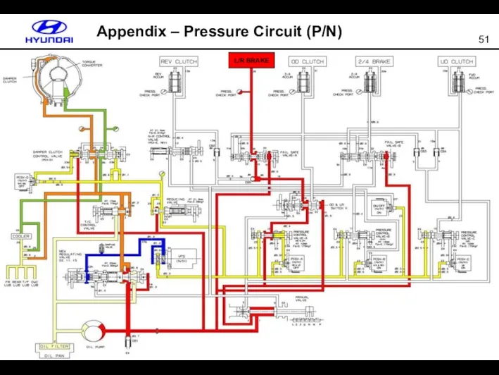
- 17. Pressure Circuit (P/N) L/R BRAKE
- 18. * Advantage : To improve fuel consumption reducing unnecessary high pressure so as to decrease fuel
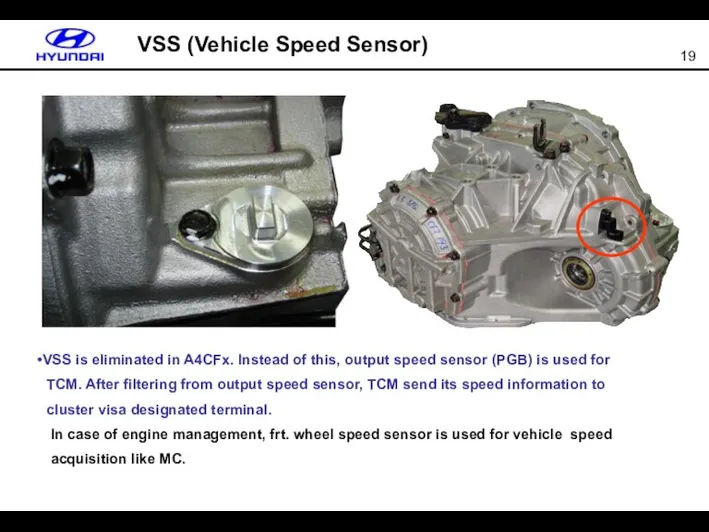
- 19. VSS (Vehicle Speed Sensor) VSS is eliminated in A4CFx. Instead of this, output speed sensor (PGB)
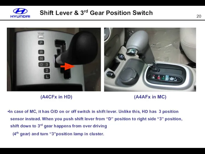
- 20. Shift Lever & 3rd Gear Position Switch (A4CFx in HD) (A4AFx in MC) In case of
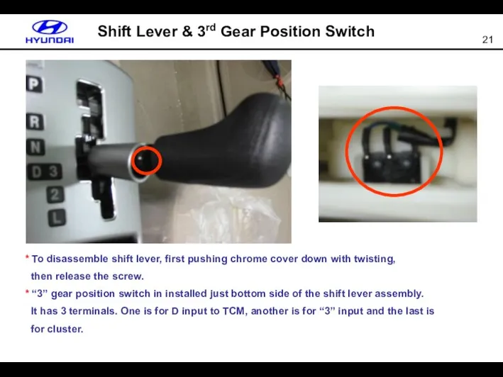
- 21. Shift Lever & 3rd Gear Position Switch * To disassemble shift lever, first pushing chrome cover
- 22. Inhibitor Switch
- 23. FPC (Flexible Printed Circuit) Harness 10P CONN INLINE CONN VFS PCSV CONN OTS 10P CONN INLINE
- 24. Operation Chart
- 25. Input & Output Input PCM ( TCM ) Battery Power GND PG-A & PG-B OTS Inhibitor
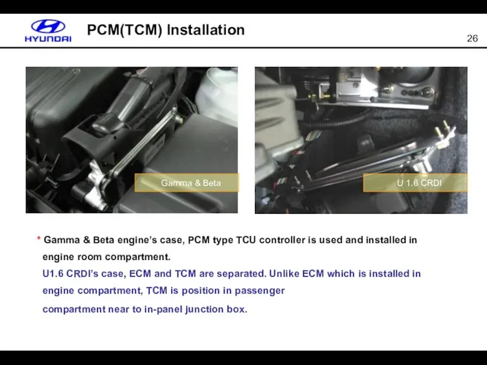
- 26. PCM(TCM) Installation * Gamma & Beta engine’s case, PCM type TCU controller is used and installed
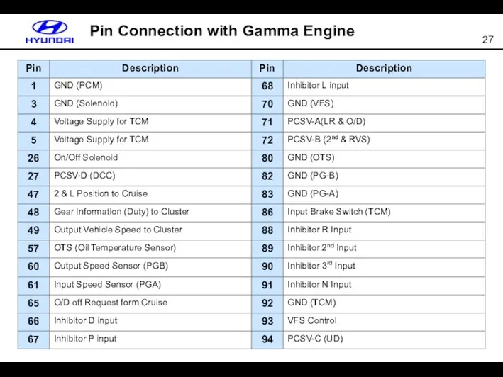
- 27. Pin Connection with Gamma Engine
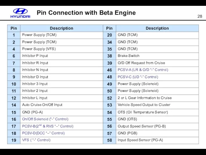
- 28. Pin Connection with Beta Engine
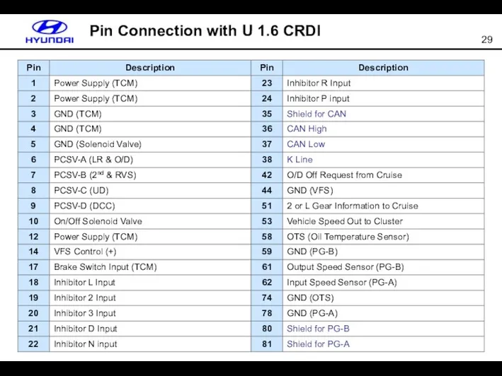
- 29. Pin Connection with U 1.6 CRDI
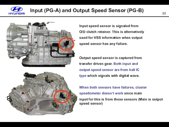
- 30. Input (PG-A) and Output Speed Sensor (PG-B) Input speed sensor is signaled from O/D clutch retainer.
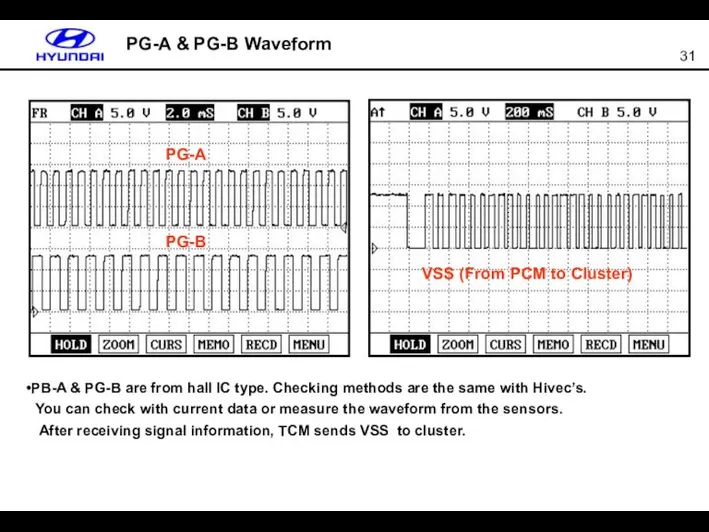
- 31. PG-A & PG-B Waveform PG-A PG-B PB-A & PG-B are from hall IC type. Checking methods
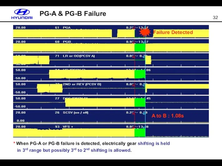
- 32. PG-A & PG-B Failure * When PG-A or PG-B failure is detected, electrically gear shifting is
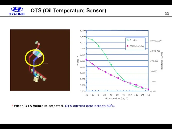
- 33. OTS (Oil Temperature Sensor) * When OTS failure is detected, OTS current data sets to 80℃.
- 34. GND Solenoid Valve (Bosch vs Siemens) UD 2nd OD LR DCC VFS UD(-) (PCSV-C) 2nd(-) (PCSV-B)
- 35. Solenoid Valve Current Control VFS PCSV & SCSV
- 36. UD Solenoid V/V On/Off Solenoid V/V VFS Solenoid V/V Solenoid Valve Waveform * In case of
- 37. P-R-N-D Shifting P R N D * After ignition, solenoid failure checking is done within 300ms
- 38. Solenoid Valve Fail (3rd Gear Fixed) A to B : 1.8s * SCSV solenoid valve shorts
- 39. 3rd Position Input (O/D Off) * In stead of O/D off switch in MC (A4AFx), HD
- 40. Stall Test L 2 3 R
- 41. Resetting Auto T/A Values
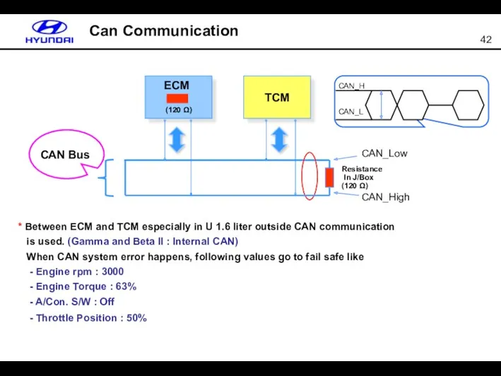
- 42. TCM CAN Bus CAN_Low CAN_High CAN_L CAN_H Resistance In J/Box (120 Ω) ECM (120 Ω) Can
- 43. CAN Data in Failure
- 44. Current Data (P&N)
- 45. Current Data (R)
- 46. Current Data (D-1)
- 47. Current Data (D-2)
- 48. Current Data (D-3)
- 49. Current Data (D-4)
- 50. Field Case – Oil Leakage Air Bleeding Cap Oil Level Gauge Taper Plug Manual Shaft
- 51. Appendix – Pressure Circuit (P/N) L/R BRAKE
- 52. Appendix – Pressure Circuit (R) L/R BRAKE REV CLUTCH
- 53. Appendix – Pressure Circuit (D1) UD CLUTCH
- 54. Appendix – Pressure Circuit (D2) UD CLUTCH 2/4 BRAKE
- 55. Appendix – Pressure Circuit (D3) UD CLUTCH OD CLUTCH
- 57. Скачать презентацию
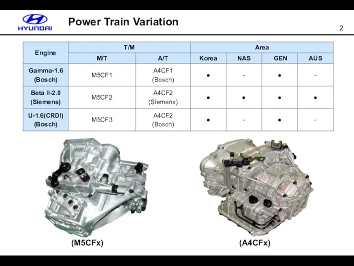
Power Train Variation
(A4CFx)
(M5CFx)
Power Train Variation
(A4CFx)
(M5CFx)
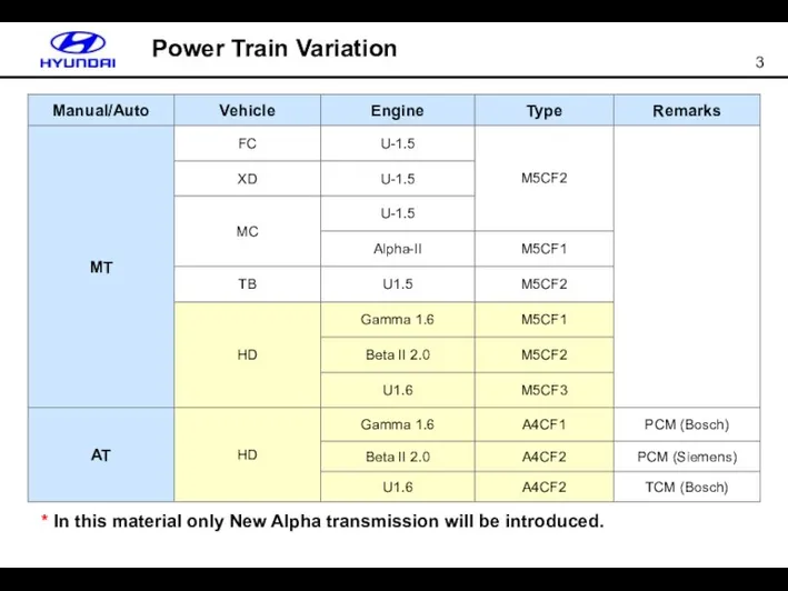
* In this material only New Alpha transmission will be introduced.
Power
* In this material only New Alpha transmission will be introduced.
Power
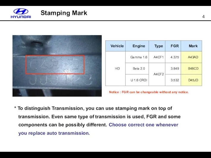
* To distinguish Transmission, you can use stamping mark on top
* To distinguish Transmission, you can use stamping mark on top
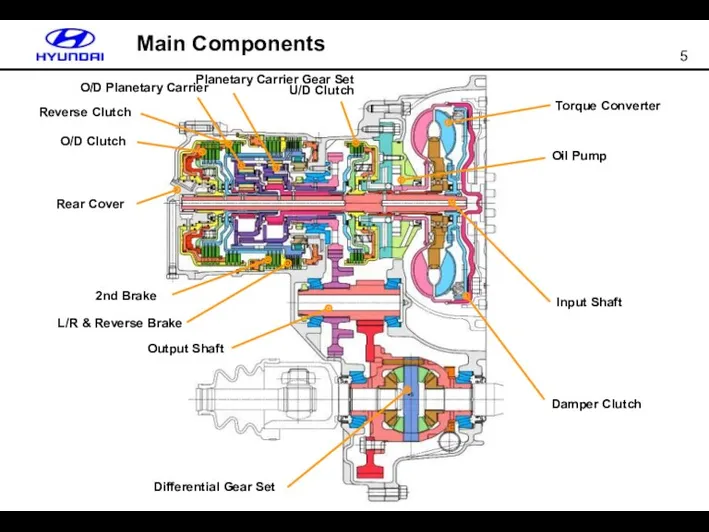
Main Components
Reverse Clutch
O/D Clutch
Rear Cover
2nd Brake
L/R & Reverse Brake
Output Shaft
Differential Gear
Main Components
Reverse Clutch
O/D Clutch
Rear Cover
2nd Brake
L/R & Reverse Brake
Output Shaft
Differential Gear
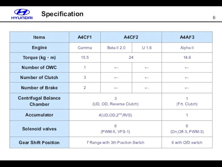
Comparison
Specification
Comparison
Specification
Comparison
Specification
Comparison
Specification
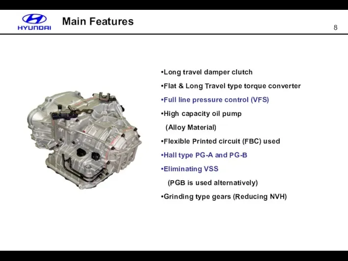
Main Features
Long travel damper clutch
Flat & Long Travel type torque converter
Full
Main Features
Long travel damper clutch
Flat & Long Travel type torque converter
Full
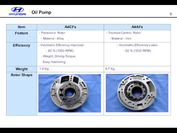
Oil Pump
Oil Pump
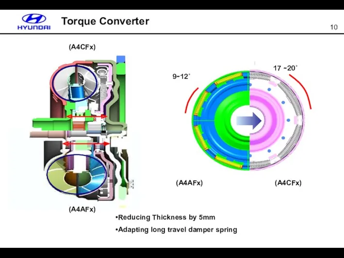
Torque Converter
Reducing Thickness by 5mm
Adapting long travel damper spring
Torque Converter
Reducing Thickness by 5mm
Adapting long travel damper spring
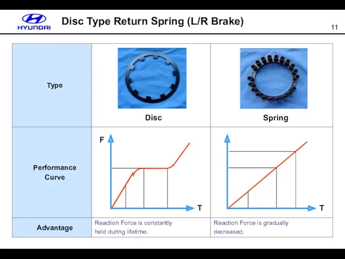
Disc Type Return Spring (L/R Brake)
Disc
Spring
T
F
T
Disc Type Return Spring (L/R Brake)
Disc
Spring
T
F
T
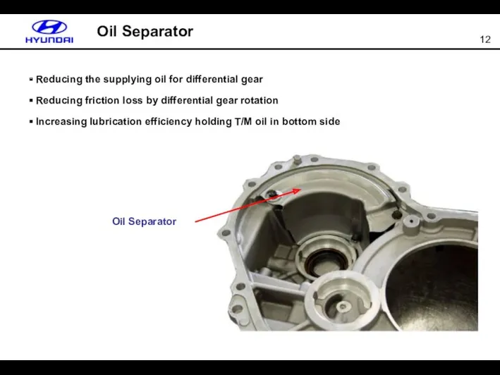
Reducing the supplying oil for differential gear
Reducing friction loss
Reducing the supplying oil for differential gear
Reducing friction loss
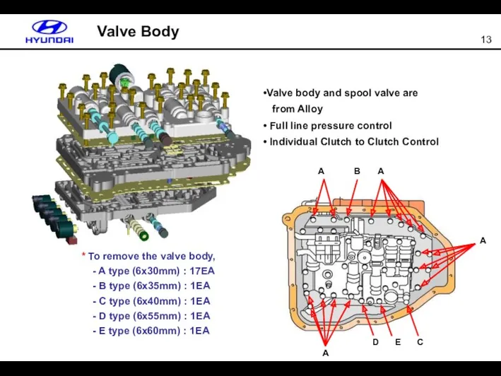
Valve Body
Valve body and spool valve are
from Alloy
Full
Valve Body
Valve body and spool valve are
from Alloy
Full
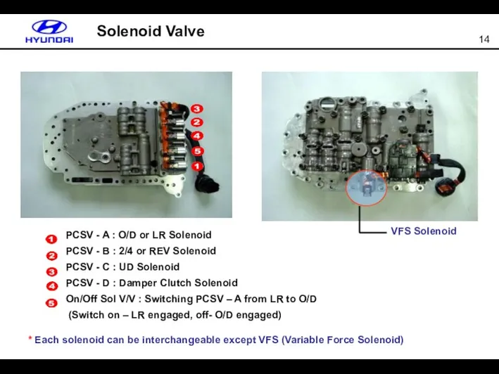
PCSV - A : O/D or LR Solenoid
PCSV -
PCSV - A : O/D or LR Solenoid
PCSV -
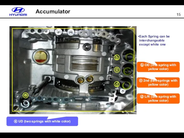
Accumulator
Each Spring can be interchangeable except white one
ⓑ
ⓒ
ⓓ
ⓐ UD (two springs
Accumulator
Each Spring can be interchangeable except white one
ⓑ
ⓒ
ⓓ
ⓐ UD (two springs
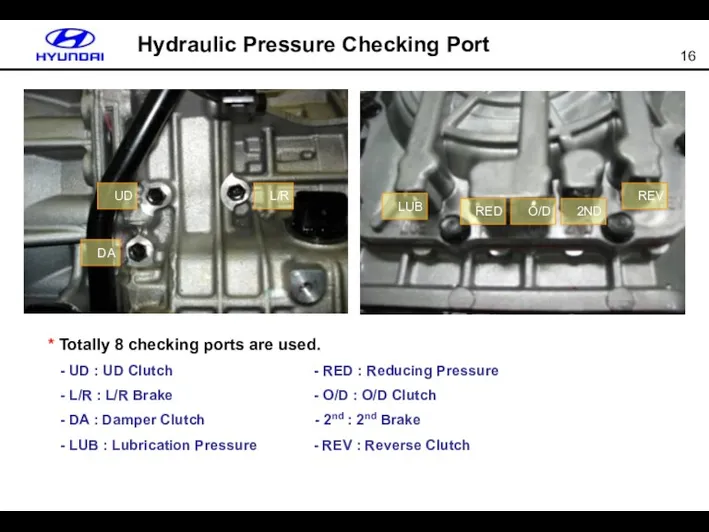
Hydraulic Pressure Checking Port
* Totally 8 checking ports are used.
Hydraulic Pressure Checking Port
* Totally 8 checking ports are used.
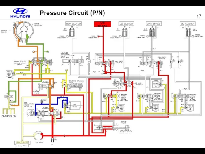
Pressure Circuit (P/N)
L/R BRAKE
Pressure Circuit (P/N)
L/R BRAKE
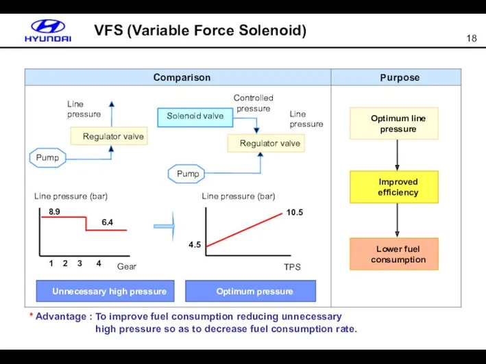
* Advantage : To improve fuel consumption reducing unnecessary
high
* Advantage : To improve fuel consumption reducing unnecessary
high
VSS (Vehicle Speed Sensor)
VSS is eliminated in A4CFx. Instead of this,
VSS (Vehicle Speed Sensor)
VSS is eliminated in A4CFx. Instead of this,
Shift Lever & 3rd Gear Position Switch
(A4CFx in HD)
(A4AFx in MC)
In
Shift Lever & 3rd Gear Position Switch
(A4CFx in HD)
(A4AFx in MC)
In
Shift Lever & 3rd Gear Position Switch
* To disassemble shift
Shift Lever & 3rd Gear Position Switch
* To disassemble shift
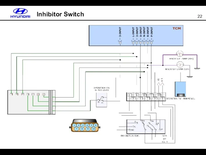
Inhibitor Switch
Inhibitor Switch
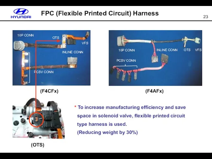
FPC (Flexible Printed Circuit) Harness
10P CONN
INLINE CONN
VFS
PCSV CONN
OTS
10P CONN
INLINE CONN
VFS
PCSV CONN
OTS
*
FPC (Flexible Printed Circuit) Harness
10P CONN
INLINE CONN
VFS
PCSV CONN
OTS
10P CONN
INLINE CONN
VFS
PCSV CONN
OTS
*
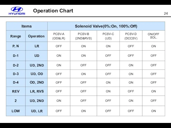
Operation Chart
Operation Chart
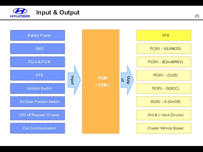
Input & Output
Input
PCM
( TCM )
Battery Power
GND
PG-A & PG-B
OTS
Inhibitor Switch
3rd Gear Position
Input & Output
Input
PCM
( TCM )
Battery Power
GND
PG-A & PG-B
OTS
Inhibitor Switch
3rd Gear Position
PCM(TCM) Installation
* Gamma & Beta engine’s case, PCM type TCU controller
PCM(TCM) Installation
* Gamma & Beta engine’s case, PCM type TCU controller
Pin Connection with Gamma Engine
Pin Connection with Gamma Engine
Pin Connection with Beta Engine
Pin Connection with Beta Engine
Pin Connection with U 1.6 CRDI
Pin Connection with U 1.6 CRDI
Input (PG-A) and Output Speed Sensor (PG-B)
Input speed sensor is signaled
Input (PG-A) and Output Speed Sensor (PG-B)
Input speed sensor is signaled
PG-A & PG-B Waveform
PG-A
PG-B
PB-A & PG-B are from hall IC type.
PG-A & PG-B Waveform
PG-A
PG-B
PB-A & PG-B are from hall IC type.
PG-A & PG-B Failure
* When PG-A or PG-B failure is detected,
PG-A & PG-B Failure
* When PG-A or PG-B failure is detected,
OTS (Oil Temperature Sensor)
* When OTS failure is detected, OTS current
OTS (Oil Temperature Sensor)
* When OTS failure is detected, OTS current
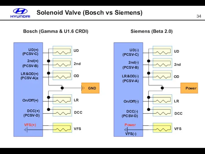
GND
Solenoid Valve (Bosch vs Siemens)
UD
2nd
OD
LR
DCC
VFS
UD(-)
(PCSV-C)
2nd(-)
(PCSV-B)
LR&OD(-)
(PCSV-A)
On/Off(-)
DCC(-)
(PCSV-D)
Power
Siemens (Beta 2.0)
VFS(-)
Bosch (Gamma & U1.6 CRDI)
UD
2nd
OD
LR
DCC
VFS
UD(+)
(PCSV-C)
2nd(+)
(PCSV-B)
LR&OD(+)
(PCSV-A)z
On/Off(+)
DCC(+)
(PCSV-D)
VFS(+)
Power
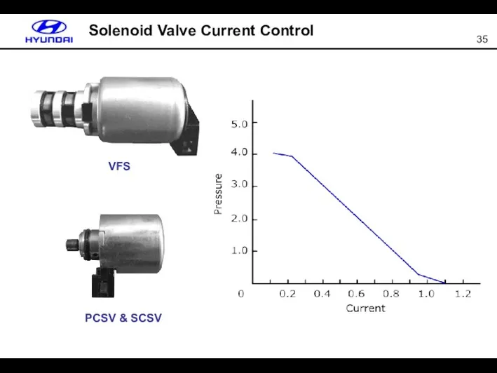
Solenoid Valve Current Control
VFS
PCSV & SCSV
Solenoid Valve Current Control
VFS
PCSV & SCSV
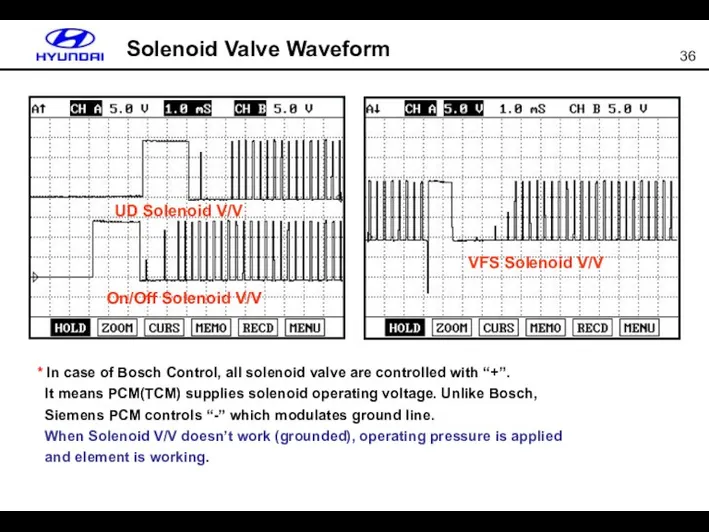
UD Solenoid V/V
On/Off Solenoid V/V
VFS Solenoid V/V
Solenoid Valve Waveform
* In case
UD Solenoid V/V
On/Off Solenoid V/V
VFS Solenoid V/V
Solenoid Valve Waveform
* In case
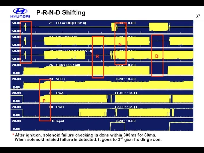
P-R-N-D Shifting
P
R
N
D
* After ignition, solenoid failure checking is done within 300ms
P-R-N-D Shifting
P
R
N
D
* After ignition, solenoid failure checking is done within 300ms
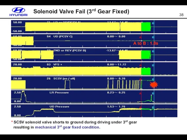
Solenoid Valve Fail (3rd Gear Fixed)
A to B : 1.8s
* SCSV
Solenoid Valve Fail (3rd Gear Fixed)
A to B : 1.8s
* SCSV
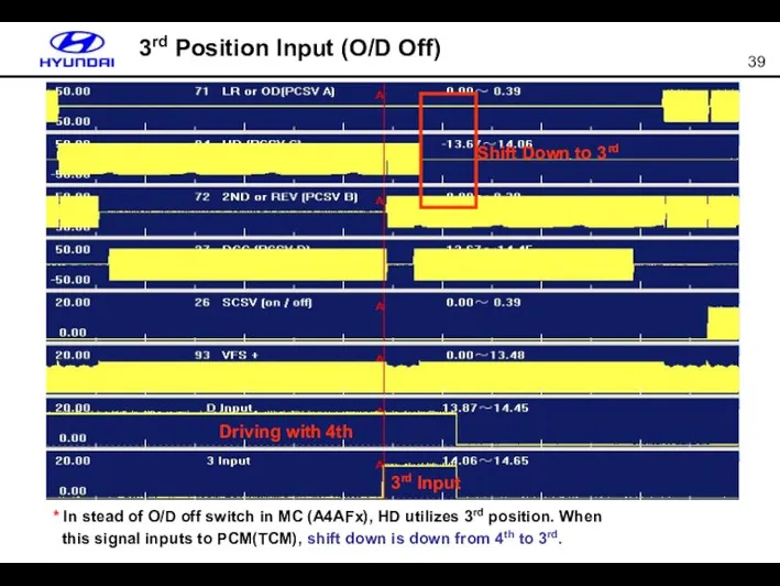
3rd Position Input (O/D Off)
* In stead of O/D off switch
3rd Position Input (O/D Off)
* In stead of O/D off switch
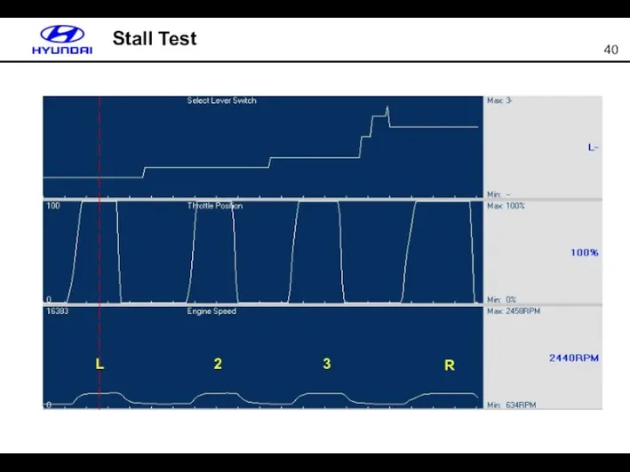
Stall Test
L
2
3
R
Stall Test
L
2
3
R
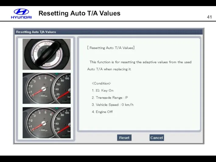
Resetting Auto T/A Values
Resetting Auto T/A Values
TCM
CAN Bus
CAN_Low
CAN_High
CAN_L
CAN_H
Resistance
In J/Box
(120 Ω)
ECM
(120 Ω)
Can Communication
* Between ECM and TCM
TCM
CAN Bus
CAN_Low
CAN_High
CAN_L
CAN_H
Resistance
In J/Box
(120 Ω)
ECM
(120 Ω)
Can Communication
* Between ECM and TCM
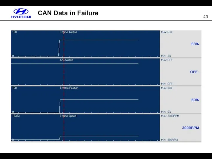
CAN Data in Failure
CAN Data in Failure
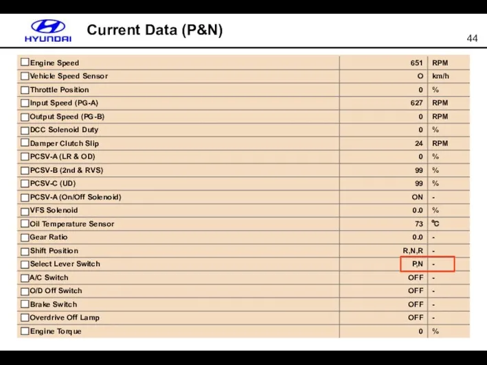
Current Data (P&N)
Current Data (P&N)
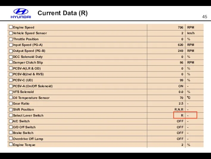
Current Data (R)
Current Data (R)

Current Data (D-1)
Current Data (D-1)

Current Data (D-2)
Current Data (D-2)
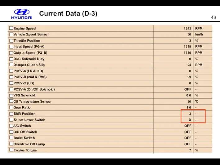
Current Data (D-3)
Current Data (D-3)
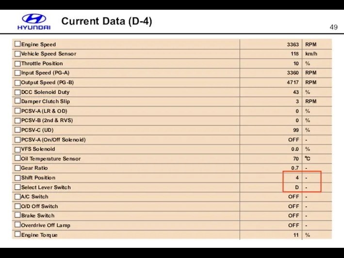
Current Data (D-4)
Current Data (D-4)
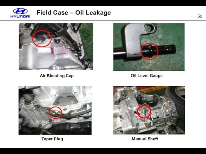
Field Case – Oil Leakage
Air Bleeding Cap
Oil Level Gauge
Taper Plug
Manual Shaft
Field Case – Oil Leakage
Air Bleeding Cap
Oil Level Gauge
Taper Plug
Manual Shaft
Appendix – Pressure Circuit (P/N)
L/R BRAKE
Appendix – Pressure Circuit (P/N)
L/R BRAKE
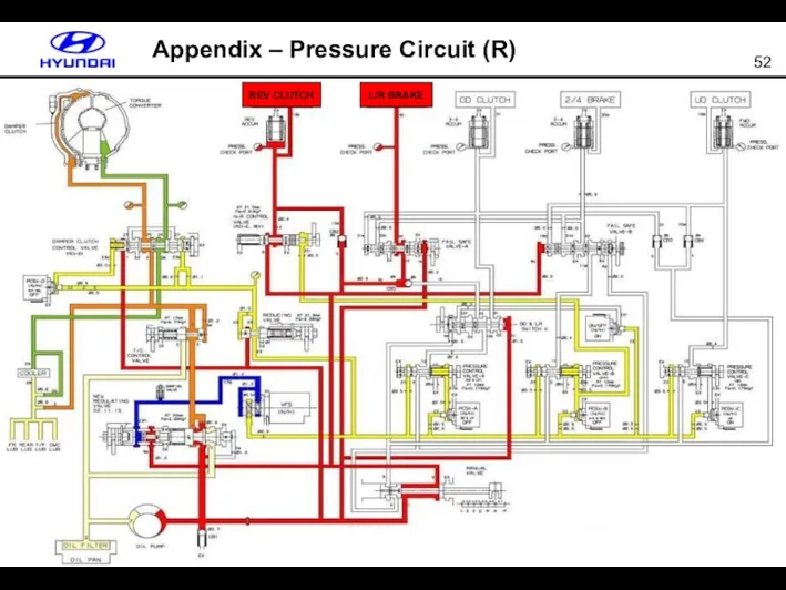
Appendix – Pressure Circuit (R)
L/R BRAKE
REV CLUTCH
Appendix – Pressure Circuit (R)
L/R BRAKE
REV CLUTCH
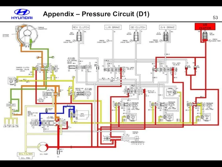
Appendix – Pressure Circuit (D1)
UD CLUTCH
Appendix – Pressure Circuit (D1)
UD CLUTCH
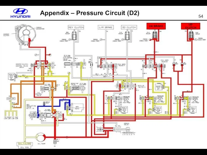
Appendix – Pressure Circuit (D2)
UD CLUTCH
2/4 BRAKE
Appendix – Pressure Circuit (D2)
UD CLUTCH
2/4 BRAKE
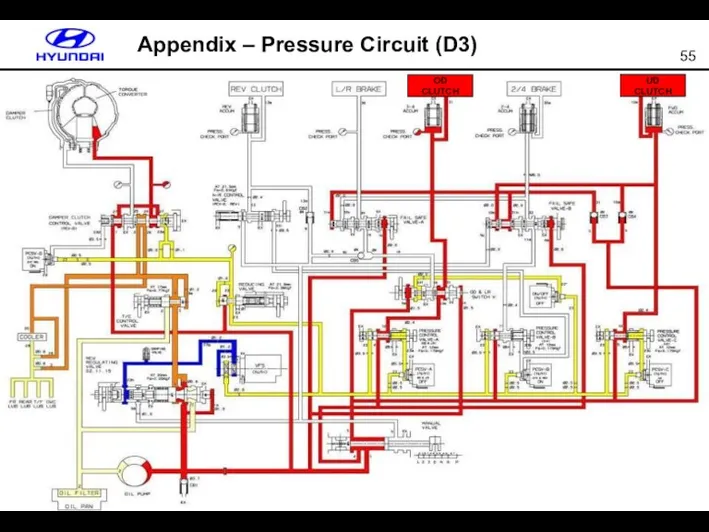
Appendix – Pressure Circuit (D3)
UD CLUTCH
OD CLUTCH
Appendix – Pressure Circuit (D3)
UD CLUTCH
OD CLUTCH
 Механическая работа
 Модуляция и детектирование
 Тележка электровоза ВЛ80р
 Расчет сложных электрических цепей постоянного тока
 Физические основы гемодинамики
 Резка металла
 Законы сохранения в механике
 Электрические машины постоянного тока
 Расчет потенциалов простейших электростатических полей
 Лазеры. Лазерное излучение
 Сақталу заңдары
 Механические волны
 Методы люминисцентного анализа
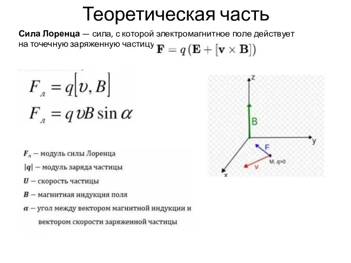 Сила Лоренца. Теоретическая часть
 Гидравлика. Основные свойства жидкостей
 Совершенствование ГБЦ двигателя МеМЗ 307
 Адсорбция изотермалары
 Что такое электричество?
 Гидравлический удар. Описание процесса
 Масса. Взаимодействие тел
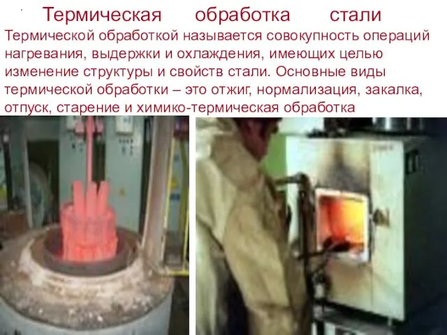 Термическая обработка стали
 Физические методы исследования в химии
 Преподавание физики в 2012-13 уч.году
 Система питания дизельного двигателя
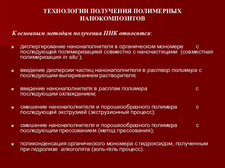 Технологии получения полимерных нанокомпозитов
 Магні́тне по́ле
 Простые механизмы. Рычаг. Равновесие сил на рычаге
 Кванттық теорияның бастаулары