- Fuel supply system DC9 EDC MS5

Содержание
- 2. Remarks Links
- 3. This chapter introduces the basic theory, the functionality and location of the supply system components Chapter
- 4. Module 1 estimated time ……. This module introduces the general structure of the fuel supply system
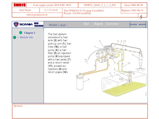
- 5. Remarks Text WSM 03:01-01 page 4 modified Picture 120 444 modified Module 1, page 1 The
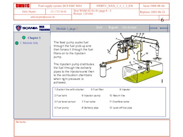
- 6. Remarks Text WSM 03:01-01 page 4 - 5 Picture 120 444 Module 1, page 2 The
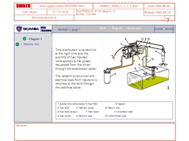
- 7. Remarks Text WSM 03:01-01 page 4 - 5 Picture 120 444 Module 1, page 3 This
- 8. Module 1 Question 1 (45 sec) In the supply circuit, what is the feed pump used
- 9. Module 2 estimated time ……. This module introduces the components of the fuel tank and lines
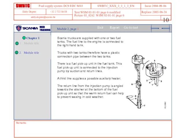
- 10. Remarks Text WSM 03:01-01 page 6 modified Picture 03_0262 WSM 03:01-01 page 6 Module 2, page
- 11. Text WSM 03:01-01 page 6 Picture 03_0253 WSM 03:01-01 page 6 Remarks Module 2, page 2
- 12. Module 2 Question 1 (40 sec) A vehicle fitted with two tanks is equipped with: An
- 13. Module 2 Question 2 (40 sec) The return pipe coming from the injection pump is angled
- 14. Module 3 estimated time ……. This module introduces the fuel valve, as well as its location
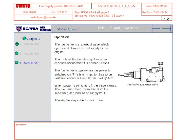
- 15. Text WSM 03:01-01 page 7 Picture 03_0800 WSM 03:01-01 page 7 Remarks Module 3, page 1
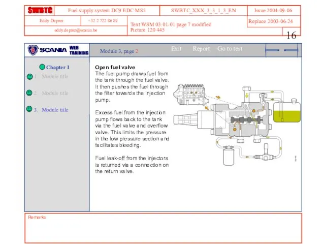
- 16. Remarks Text WSM 03:01-01 page 7 modified Picture 120 445 Module 3, page 2 Open fuel
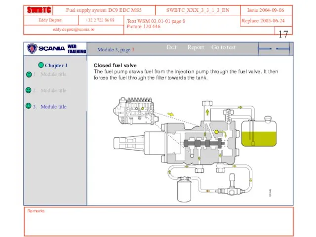
- 17. Remarks Text WSM 03:01-01 page 8 Picture 120 446 Module 3, page 3 Closed fuel valve
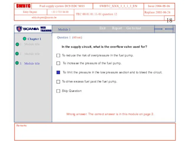
- 18. Module 3 Question 1 (40 sec) In the supply circuit, what is the overflow valve used
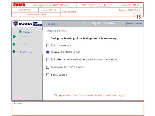
- 19. Module 3 Question 2 (40 sec) During the bleeding of the fuel system, it is necessary:
- 20. Module 4 estimated time ……. This module introduces the fuel pump, as well as its location
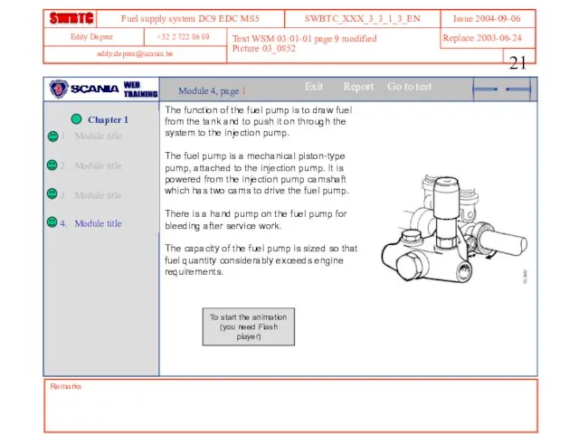
- 21. Remarks Text WSM 03:01-01 page 9 modified Picture 03_0852 Module 4, page 1 The function of
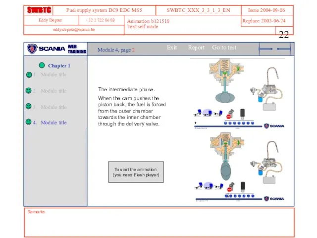
- 22. Remarks Animation b121518 Text self made Module 4, page 2 The intermediate phase. When the cam
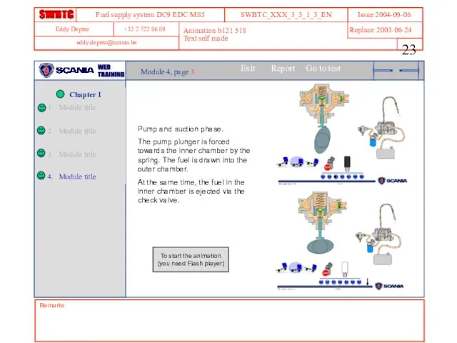
- 23. Remarks Animation b121 518 Text self made Module 4, page 3 Pump and suction phase. The
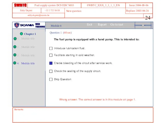
- 24. Module 4 Question 1 (40 sec) The fuel pump is equipped with a hand pump. This
- 25. Module 5 estimated time ……. This module introduces the fuel filter, as well as its location
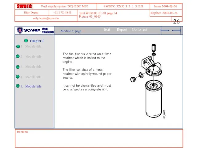
- 26. Remarks Text WSM 03:01-01 page 14 Picture 03_0865 Module 5, page 1 The fuel filter is
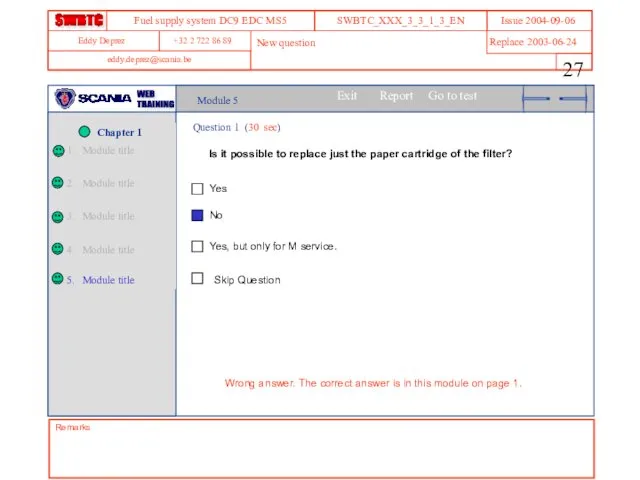
- 27. Module 5 Question 1 (30 sec) Is it possible to replace just the paper cartridge of
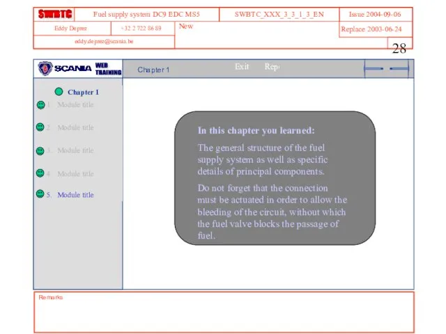
- 28. In this chapter you learned: The general structure of the fuel supply system as well as
- 29. This chapter introduces the injection pump and the injectors Chapter 2 estimated time ……. Links Remarks
- 30. Module 1 estimated time ... This module introduces the injection pump Links Remarks Links
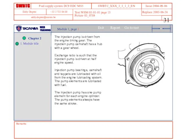
- 31. Text WSM 03:01-01 page 15 Picture 03_0789 Remarks Module 1, page 1 The injection pump is
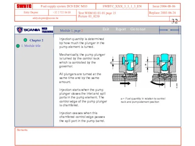
- 32. Remarks Text WSM 03:01-01 page 15 Picture 03_0259 Module 1, page 2 Injection quantity is determined
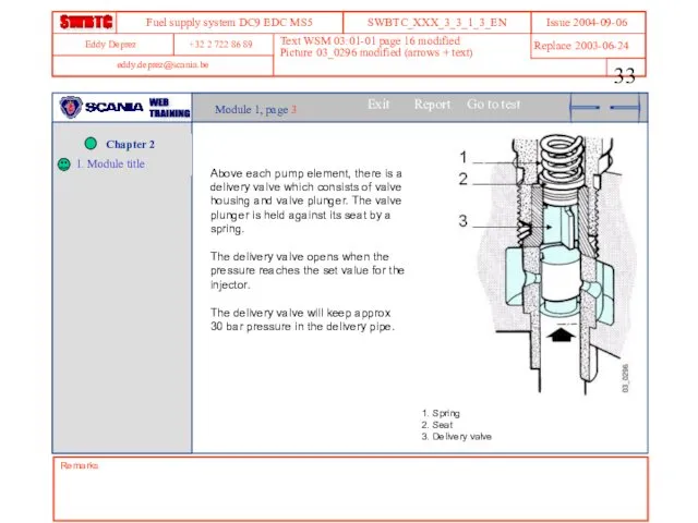
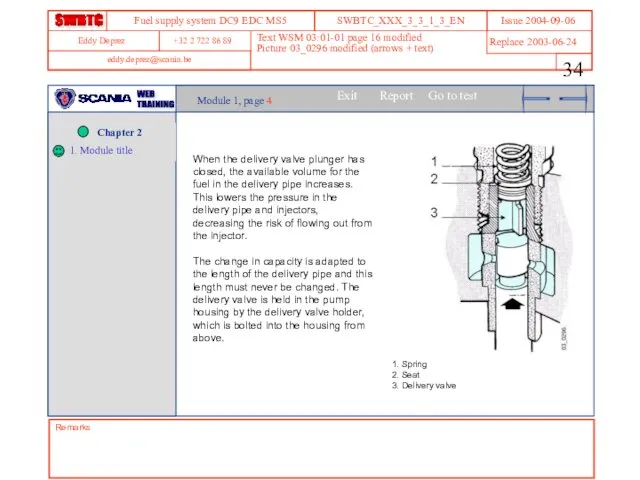
- 33. Remarks Text WSM 03:01-01 page 16 modified Picture 03_0296 modified (arrows + text) Module 1, page
- 34. Remarks Text WSM 03:01-01 page 16 modified Picture 03_0296 modified (arrows + text) Module 1, page
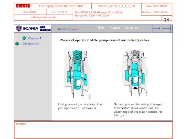
- 35. Remarks Text WSM 03:01-01 page 17 modified Picture 03_0264 + 03_0265 Module 1, page 5 Phases
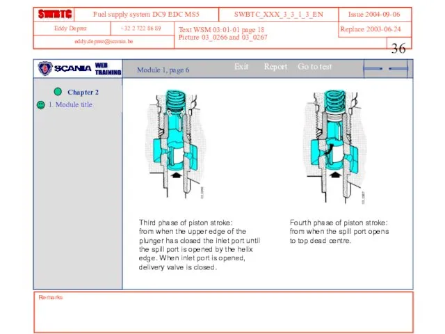
- 36. Remarks Text WSM 03:01-01 page 18 Picture 03_0266 and 03_0267 Module 1, page 6 Third phase
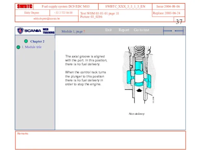
- 37. Remarks Text WSM 03:01-01 page 18 Picture 03_0296 Module 1, page 7 The axial groove is
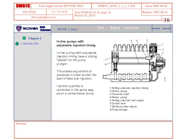
- 38. Remarks Text WSM 03:01-01 page 16 Picture 03_0870 Module 1, page 8 In-line pumps with adjustable
- 39. Module 1 Question 1 (40 sec) The injection pump runs at a speed: Equivalent to double
- 40. Module 1 Question 2 (40 sec) The rotation of a pump element piston influences: The time
- 41. Module 1 Question 3 (40 sec) After injection, when the pressure valve is closed again, pressure
- 42. Module 2 estimated time ……. This module introduces the injector and the delivery pipe Remarks Links
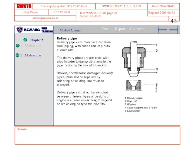
- 43. Remarks Text WSM 03:01-01 page 20 Picture 03_0855 Module 2, page 1 Delivery pipe Delivery pipes
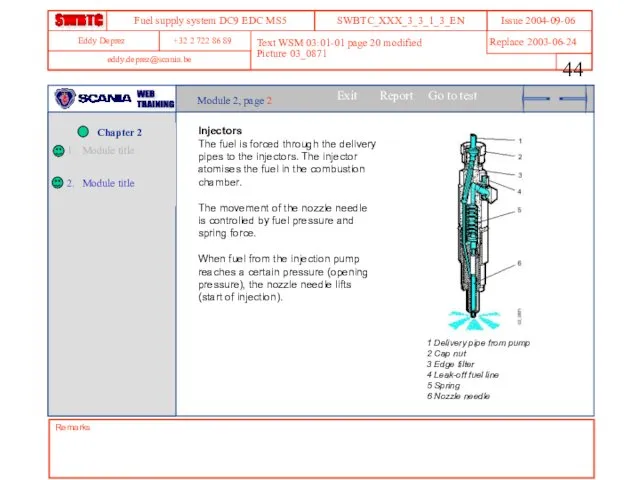
- 44. Remarks Text WSM 03:01-01 page 20 modified Picture 03_0871 Module 2, page 2 Injectors The fuel
- 45. Remarks Text WSM 03:01-01 page 20 modified Picture 03_0871 Module 2, page 3 The fuel is
- 46. Module 2 Question 1 (40 sec) The opening pressure of the injector depends on: The pressure
- 48. Скачать презентацию
Remarks
Links
Remarks
Links
This chapter introduces the basic theory, the functionality and location of
This chapter introduces the basic theory, the functionality and location of

Module 1 estimated time …….
This module introduces
the general structure of
Module 1 estimated time …….
This module introduces the general structure of
Remarks
Text WSM 03:01-01 page 4 modified
Picture 120 444 modified
Module 1, page
Remarks
Text WSM 03:01-01 page 4 modified
Picture 120 444 modified
Module 1, page
Remarks
Text WSM 03:01-01 page 4 - 5
Picture 120 444
Module 1, page
Remarks
Text WSM 03:01-01 page 4 - 5
Picture 120 444
Module 1, page
Remarks
Text WSM 03:01-01 page 4 - 5
Picture 120 444
Module 1, page
Remarks
Text WSM 03:01-01 page 4 - 5
Picture 120 444
Module 1, page
Module 1
Question 1 (45 sec)
In the supply circuit, what is the
Module 1
Question 1 (45 sec)
In the supply circuit, what is the

Module 2 estimated time …….
This module introduces the components of the
Module 2 estimated time …….
This module introduces the components of the
Remarks
Text WSM 03:01-01 page 6 modified
Picture 03_0262 WSM 03:01-01 page 6
Module
Remarks
Text WSM 03:01-01 page 6 modified
Picture 03_0262 WSM 03:01-01 page 6
Module
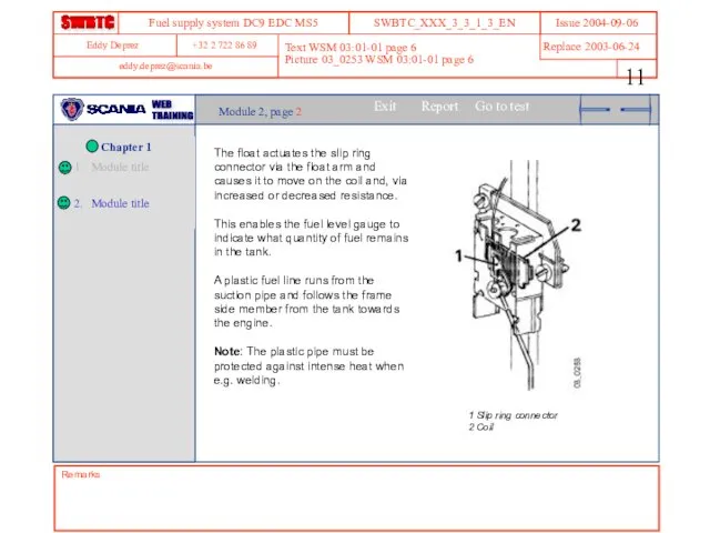
Text WSM 03:01-01 page 6
Picture 03_0253 WSM 03:01-01 page 6
Remarks
Module 2,
Text WSM 03:01-01 page 6
Picture 03_0253 WSM 03:01-01 page 6
Remarks
Module 2,
Module 2
Question 1 (40 sec)
A vehicle fitted with two tanks is
Module 2
Question 1 (40 sec)
A vehicle fitted with two tanks is
Module 2
Question 2 (40 sec)
The return pipe coming from the injection
Module 2
Question 2 (40 sec)
The return pipe coming from the injection

Module 3 estimated time …….
This module introduces the
fuel valve, as
Module 3 estimated time …….
This module introduces the fuel valve, as
Text WSM 03:01-01 page 7
Picture 03_0800 WSM 03:01-01 page 7
Remarks
Module 3,
Text WSM 03:01-01 page 7
Picture 03_0800 WSM 03:01-01 page 7
Remarks
Module 3,
Remarks
Text WSM 03:01-01 page 7 modified
Picture 120 445
Module 3, page 2
Open
Remarks
Text WSM 03:01-01 page 7 modified
Picture 120 445
Module 3, page 2
Open
Remarks
Text WSM 03:01-01 page 8
Picture 120 446
Module 3, page 3
Closed fuel
Remarks
Text WSM 03:01-01 page 8
Picture 120 446
Module 3, page 3
Closed fuel
Module 3
Question 1 (40 sec)
In the supply circuit, what is the
Module 3
Question 1 (40 sec)
In the supply circuit, what is the
Module 3
Question 2 (40 sec)
During the bleeding of the fuel system,
Module 3
Question 2 (40 sec)
During the bleeding of the fuel system,
Module 4 estimated time …….
This module introduces the
fuel pump, as
Module 4 estimated time …….
This module introduces the fuel pump, as
Remarks
Text WSM 03:01-01 page 9 modified
Picture 03_0852
Module 4, page 1
The function
Remarks
Text WSM 03:01-01 page 9 modified
Picture 03_0852
Module 4, page 1
The function
Remarks
Animation b121518
Text self made
Module 4, page 2
The intermediate phase.
When the
Remarks
Animation b121518
Text self made
Module 4, page 2
The intermediate phase.
When the
Remarks
Animation b121 518
Text self made
Module 4, page 3
Pump and suction phase.
Remarks
Animation b121 518
Text self made
Module 4, page 3
Pump and suction phase.
Module 4
Question 1 (40 sec)
The fuel pump is equipped with a
Module 4
Question 1 (40 sec)
The fuel pump is equipped with a

Module 5 estimated time …….
This module introduces the fuel filter, as
Module 5 estimated time …….
This module introduces the fuel filter, as
Remarks
Text WSM 03:01-01 page 14
Picture 03_0865
Module 5, page 1
The fuel filter
Remarks
Text WSM 03:01-01 page 14
Picture 03_0865
Module 5, page 1
The fuel filter
Module 5
Question 1 (30 sec)
Is it possible to replace just the
Module 5
Question 1 (30 sec)
Is it possible to replace just the
In this chapter you learned:
The general structure of the fuel
In this chapter you learned:
The general structure of the fuel
This chapter introduces the injection pump and the injectors
Chapter 2 estimated
Chapter 2 estimated
Module 1 estimated time ...
This module introduces the injection pump
Links
Remarks
Links
Module 1 estimated time ...
This module introduces the injection pump
Links
Remarks
Links
Text WSM 03:01-01 page 15
Picture 03_0789
Remarks
Module 1, page 1
The injection pump
Text WSM 03:01-01 page 15
Picture 03_0789
Remarks
Module 1, page 1
The injection pump
Remarks
Text WSM 03:01-01 page 15
Picture 03_0259
Module 1, page 2
Injection quantity is
Remarks
Text WSM 03:01-01 page 15
Picture 03_0259
Module 1, page 2
Injection quantity is
Remarks
Text WSM 03:01-01 page 16 modified
Picture 03_0296 modified (arrows + text)
Module
Remarks
Text WSM 03:01-01 page 16 modified
Picture 03_0296 modified (arrows + text)
Module
Remarks
Text WSM 03:01-01 page 16 modified
Picture 03_0296 modified (arrows + text)
Module
Remarks
Text WSM 03:01-01 page 16 modified
Picture 03_0296 modified (arrows + text)
Module
Remarks
Text WSM 03:01-01 page 17 modified
Picture 03_0264 + 03_0265
Module 1, page
Remarks
Text WSM 03:01-01 page 17 modified
Picture 03_0264 + 03_0265
Module 1, page
Remarks
Text WSM 03:01-01 page 18
Picture 03_0266 and 03_0267
Module 1, page 6
Third
Remarks
Text WSM 03:01-01 page 18
Picture 03_0266 and 03_0267
Module 1, page 6
Third
Remarks
Text WSM 03:01-01 page 18
Picture 03_0296
Module 1, page 7
The axial groove
Remarks
Text WSM 03:01-01 page 18
Picture 03_0296
Module 1, page 7
The axial groove
Remarks
Text WSM 03:01-01 page 16
Picture 03_0870
Module 1, page 8
In-line pumps with
Remarks
Text WSM 03:01-01 page 16
Picture 03_0870
Module 1, page 8
In-line pumps with
Module 1
Question 1 (40 sec)
The injection pump runs at a speed:
Equivalent
Module 1
Question 1 (40 sec)
The injection pump runs at a speed:
Equivalent
Module 1
Question 2 (40 sec)
The rotation of a pump element piston
Module 1
Question 2 (40 sec)
The rotation of a pump element piston
Module 1
Question 3 (40 sec)
After injection, when the pressure valve is
Module 1
Question 3 (40 sec)
After injection, when the pressure valve is
Module 2 estimated time …….
This module introduces the injector and the
Module 2 estimated time …….
This module introduces the injector and the
Remarks
Text WSM 03:01-01 page 20
Picture 03_0855
Module 2, page 1
Delivery pipe
Delivery pipes
Remarks
Text WSM 03:01-01 page 20
Picture 03_0855
Module 2, page 1
Delivery pipe
Delivery pipes
Remarks
Text WSM 03:01-01 page 20 modified
Picture 03_0871
Module 2, page 2
Injectors
The
Remarks
Text WSM 03:01-01 page 20 modified
Picture 03_0871
Module 2, page 2
Injectors
The

Remarks
Text WSM 03:01-01 page 20 modified
Picture 03_0871
Module 2, page 3
The fuel
Remarks
Text WSM 03:01-01 page 20 modified
Picture 03_0871
Module 2, page 3
The fuel
Module 2
Question 1 (40 sec)
The opening pressure of the injector depends
Module 2
Question 1 (40 sec)
The opening pressure of the injector depends
 Methods and technical means for using the energy of waves
 Презентация Механическое движение
 Экспериментальные методы исследования частиц
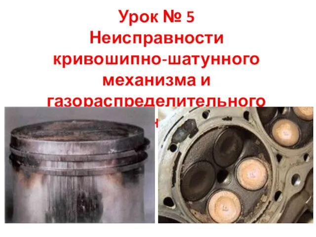 Неисправности кривошипно-шатунного механизма и газораспределительного механизма
 Свойства звука: отражение, эхо
 Лазеры ультракоротких импульсов. Фемтосекундные лазеры
 Введение в Физику
 Разработка урока по физике(с элементами робототехники) на тему наблюдение и исследование явления инерции
 Эквивалентная схема диэлектрика и диэлектрическая дисперсия
 Электрооборудование автомобилей. Схемы автомобильного бортового электрооборудования
 Архимедова сила
 Разработка урока по физике в 8 классе на тему: Последовательное и параллельное соединение проводников
 Явление электромагнитной индукции
 Активізація пізнавальної діяльності учнів на уроках фізики шляхом використання проблемних ситуацій
 Амортизаторы. Назначение амортизаторов
 Линзы. Урок 62. Изображения, даваемые линзой
 Электрический ток в газах
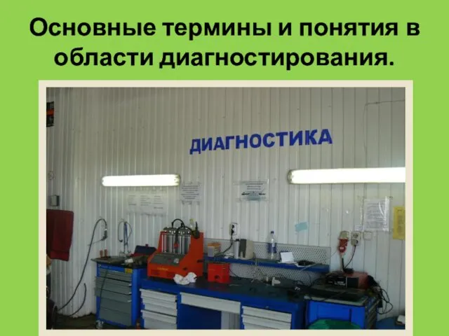 Основные термины и понятия в области диагностирования
 конспект урока физики в 7 классе Давление. Способы уменьшения и увеличения давления
 Магниттік күштік микроскопия
 Влияние электромагнитного поля на окружающую среду и человека. 8 класс
 Prezentatsia_k_preddiplomnoy_praktiki_Butin_I_A
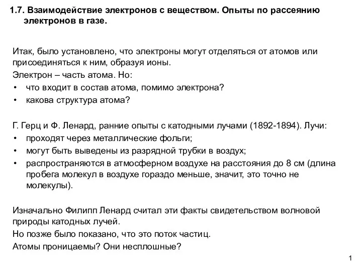 Взаимодействие электронов с веществом. Опыты по рассеянию электронов в газе. АФ1.7
 Первый закон Ньютона
 Увлекательная физика
 Испарение. Насыщенный и ненасыщенный пар
 Ядерная энергия, атомная энергия
 Радиоактивность как свидетельство сложного строения атомов