- An Introduction to GNSS_rev2_SD

Содержание
- 2. Presentation Outline GNSS Overview Basic GNSS Concepts GNSS Satellite Systems Advanced GNSS Concepts GNSS Applications and
- 3. GNSS Overview *
- 4. GNSS Overview GNSS (Global Navigation Satellite Systems) started with the launch of the U.S Department of
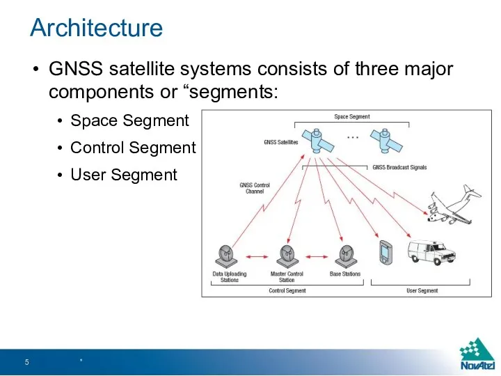
- 5. Architecture GNSS satellite systems consists of three major components or “segments: Space Segment Control Segment User
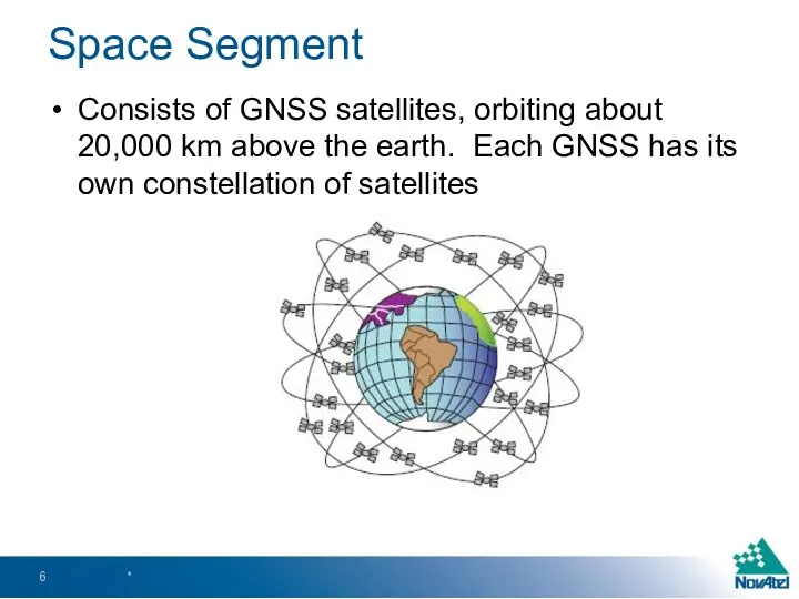
- 6. Space Segment Consists of GNSS satellites, orbiting about 20,000 km above the earth. Each GNSS has
- 7. Control Segment The control segment comprises of a ground-based network of master control stations, data uploading
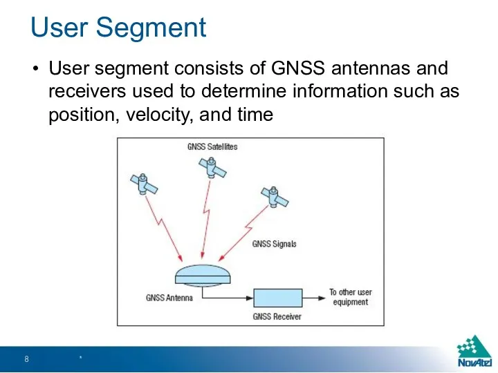
- 8. User Segment User segment consists of GNSS antennas and receivers used to determine information such as
- 9. Basic GNSS Concepts *
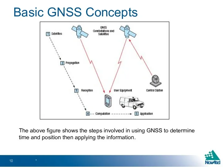
- 10. Basic GNSS Concepts * The above figure shows the steps involved in using GNSS to determine
- 11. Satellites Multiple GNSS constellations orbiting the earth Beneficial in difficult environment with obstructions to direct line
- 12. Satellites GPS transmits at the following frequencies This frequency band is referred to as the L-band,
- 13. Satellites Navigation message includes the following information: GPS date and time Satellite status and health Satellite
- 14. Propagation GNSS signals pass through the near-vacuum of space, then through the various layers of the
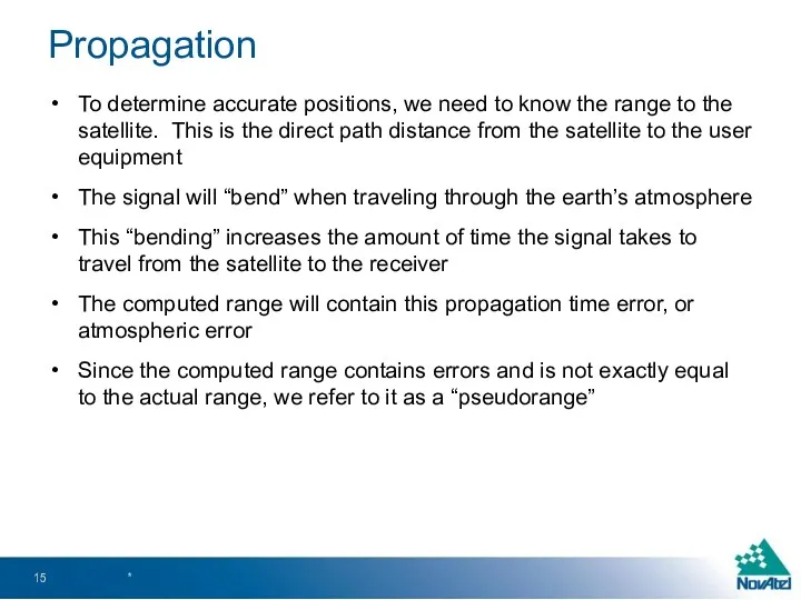
- 15. Propagation To determine accurate positions, we need to know the range to the satellite. This is
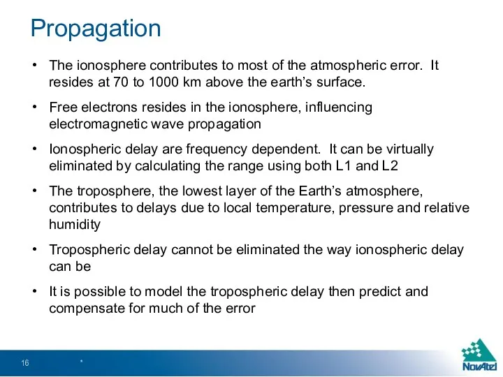
- 16. Propagation The ionosphere contributes to most of the atmospheric error. It resides at 70 to 1000
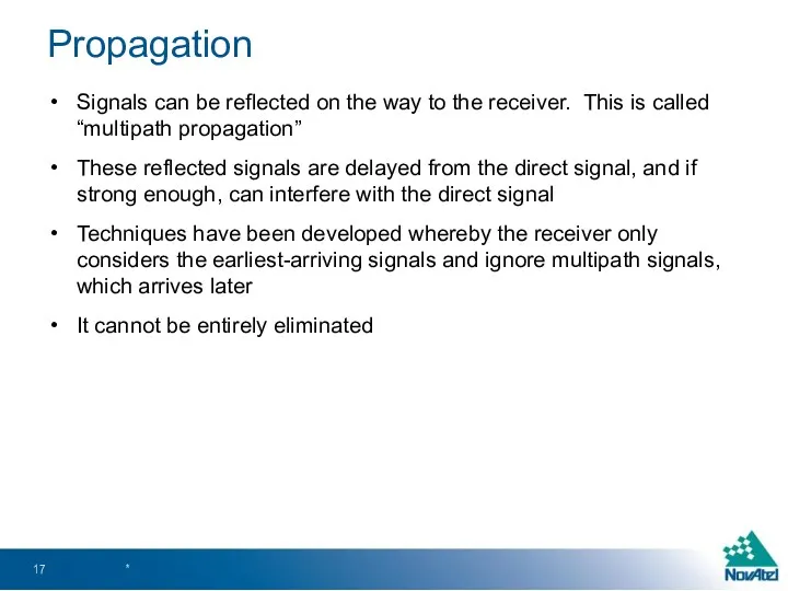
- 17. Propagation Signals can be reflected on the way to the receiver. This is called “multipath propagation”
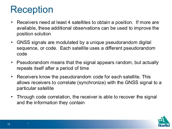
- 18. Reception Receivers need at least 4 satellites to obtain a position. If more are available, these
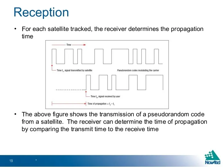
- 19. Reception For each satellite tracked, the receiver determines the propagation time The above figure shows the
- 20. Computation Range measurments from 4 satellites are needed to determine position For each satellite tracked, the
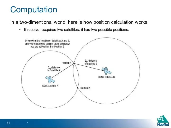
- 21. Computation In a two-dimentional world, here is how position calculation works: If receiver acquires two satellites,
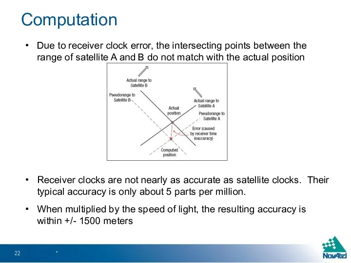
- 22. Due to receiver clock error, the intersecting points between the range of satellite A and B
- 23. When we now compute the range of the third satellite, the points will not intersect to
- 24. The receiver can advance or delay its clock until the pseudoranges to the three satellites converge
- 25. In summary, here are the GNSS error sources that affect the accuracy of pseudorange calculation: The
- 26. GNSS Satellite Systems *
- 27. Currently, the following GNSS systems are operational GPS (United States) GLONASS (Russia) The folowing GNSS systems
- 28. GPS (Global Positioning System) or NAVSTAR, as it is officially called, is the first GNSS system
- 29. The GPS space segment is summarized in the table below: The orbital period of each satellite
- 30. GPS orbits approximately 26,560 km above the Earth GPS satellites continuously broadcast their identification, ranging signals,
- 31. GPS signals are based on CDMA (Code Division Multiple Access) technology The table below provides further
- 32. GPS Control Segment consists of a master control station and a backup master control station, in
- 33. GPS space segment modernization has included new signals, as well as improvements in atomic clock accuracy,
- 34. A new GPS L5 frequency (1176.45 MHz) is slowly being added to new satellites The first
- 35. GLONASS (Global Navigation Satellite System) was developed by the Soviet Union as an experimental military communications
- 36. The GLONASS constellation provides visibility to a variable number of satellites, depending on your location The
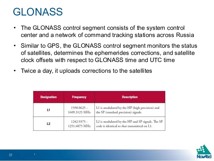
- 37. The GLONASS control segment consists of the system control center and a network of command tracking
- 38. GLONASS satellites each transmit on slightly different L1 and L2 frequencies GLONASS satellites transmit the same
- 39. The GLONASS system is based on 24 satellites using 12 frequencies. It achieves this by having
- 40. Europe’s global navigation system Guaranteed global positioning service under civilian control Guaranteed availability of service under
- 41. Once the constellation is operational, Galileo navigation signals will provide coverage at all latitudes Two Galileo
- 42. Five Galileo services are proposed: * Galileo
- 43. China’s global navigation system Initial system will provide regional coverage A target of 2015 to begin
- 44. IRNSS (India Regional Navigation Satellite System, India) Satellite system to provide regional coverage Planned to launch
- 45. Advanced GNSS Concepts
- 46. Differential GNSS uses a fixed GNSS receiver, referred to as “base station” to transmit corrections to
- 47. The base station determines ranges to the GNSS satellites by: Using the code-based positioning technique as
- 48. For corrections to be applied, the base and rover must be tracking a minimum of 4
- 49. Satellite-Based Augmentation System (SBAS) is suitable for applications where the cost of installing a base station
- 50. Reference stations receive GNSS signals and forwards them to master station Master station accurately calculates wide-area
- 51. SBAS has two level of services: Free, government-provided SBAS services in GPS frequency (except CDGPS) Commercial
- 52. Commercial SBAS system includes OmniSTAR, VERIPOS, and StarFire OmniSTAR is a subscription-based service that transmits differential
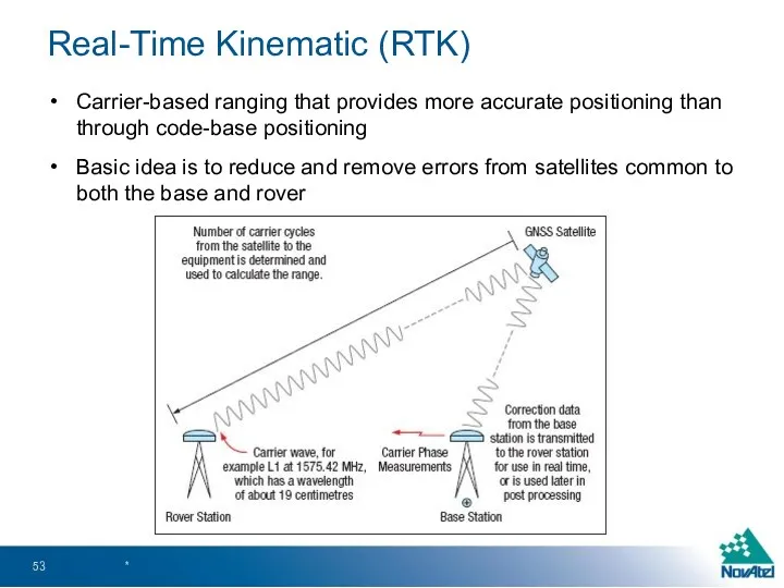
- 53. Real-Time Kinematic (RTK) Carrier-based ranging that provides more accurate positioning than through code-base positioning Basic idea
- 54. The range is calculated by determining the number of carrier cycles between the satellite and the
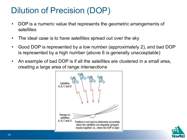
- 55. Dilution of Precision (DOP) DOP is a numeric value that represents the geometric arrangements of satellites
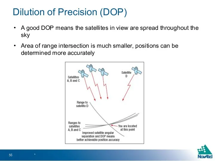
- 56. Dilution of Precision (DOP) A good DOP means the satellites in view are spread throughout the
- 57. DOP can be expressed as a number of separate elements: HDOP – Horizontal DOP VDOP –
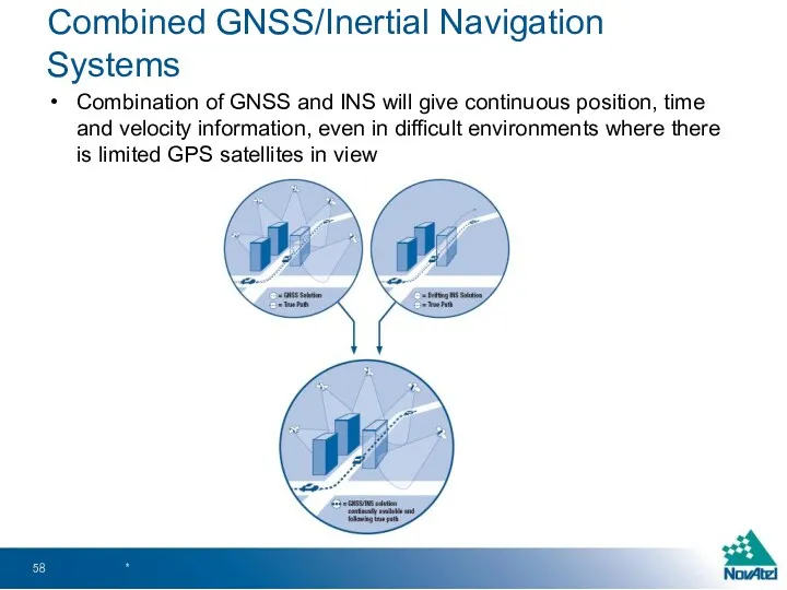
- 58. Combined GNSS/Inertial Navigation Systems Combination of GNSS and INS will give continuous position, time and velocity
- 59. INS uses rotation and acceleration information from an Inertial Measurement Unit (IMU) to compute position over
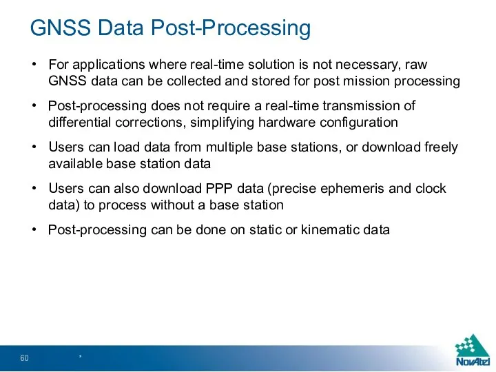
- 60. GNSS Data Post-Processing For applications where real-time solution is not necessary, raw GNSS data can be
- 61. GNSS Applications and Equipment *
- 62. Applications Some common GNSS Applications include: Transportation Timing Machine Control Marine Surveying Defence Port Automation *
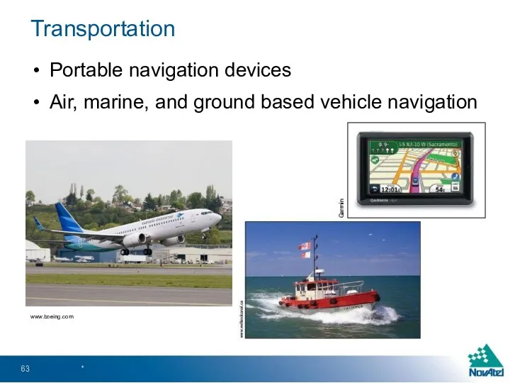
- 63. Transportation Portable navigation devices Air, marine, and ground based vehicle navigation * www.boeing.com
- 64. Machine Control *
- 65. Surveying * Google Street View
- 66. GIS * Google Map
- 67. Port Automation *
- 68. Defence *
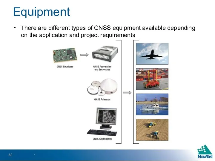
- 69. Equipment There are different types of GNSS equipment available depending on the application and project requirements
- 71. Скачать презентацию
Presentation Outline
GNSS Overview
Basic GNSS Concepts
GNSS Satellite Systems
Advanced GNSS Concepts
GNSS Applications and
Presentation Outline
GNSS Overview
Basic GNSS Concepts
GNSS Satellite Systems
Advanced GNSS Concepts
GNSS Applications and
GNSS Overview
*
GNSS Overview
*
GNSS Overview
GNSS (Global Navigation Satellite Systems) started with the launch of
GNSS Overview
GNSS (Global Navigation Satellite Systems) started with the launch of
Architecture
GNSS satellite systems consists of three major components or “segments:
Space Segment
Control
Architecture
GNSS satellite systems consists of three major components or “segments:
Space Segment
Control
Space Segment
Consists of GNSS satellites, orbiting about 20,000 km above the
Space Segment
Consists of GNSS satellites, orbiting about 20,000 km above the
Control Segment
The control segment comprises of a ground-based network of master
Control Segment
The control segment comprises of a ground-based network of master
User Segment
User segment consists of GNSS antennas and receivers used to
User Segment
User segment consists of GNSS antennas and receivers used to

Basic GNSS Concepts
*
Basic GNSS Concepts
*
Basic GNSS Concepts
*
The above figure shows the steps involved in using
Basic GNSS Concepts
*
The above figure shows the steps involved in using
Satellites
Multiple GNSS constellations orbiting the earth
Beneficial in difficult environment with obstructions
Satellites
Multiple GNSS constellations orbiting the earth
Beneficial in difficult environment with obstructions
Satellites
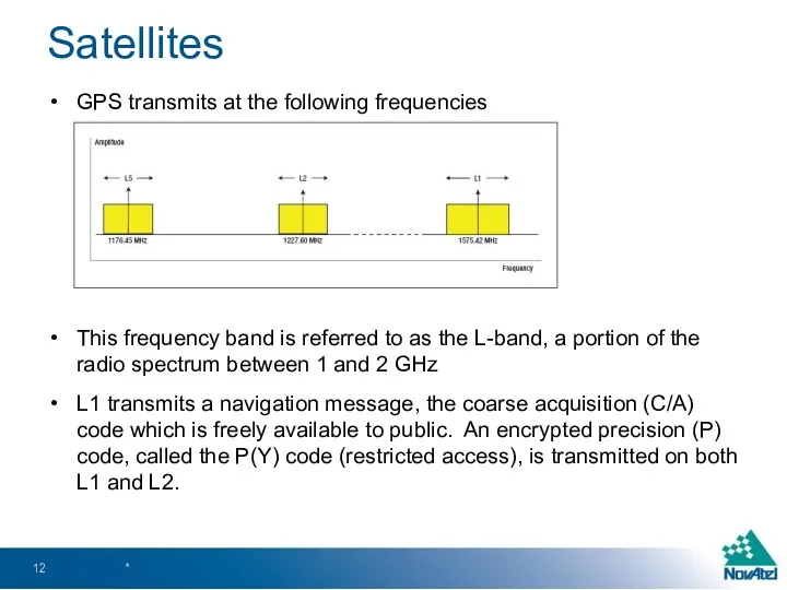
GPS transmits at the following frequencies
This frequency band is referred to
Satellites
GPS transmits at the following frequencies
This frequency band is referred to
Satellites
Navigation message includes the following information:
GPS date and time
Satellite status and
Satellites
Navigation message includes the following information:
GPS date and time
Satellite status and
Propagation
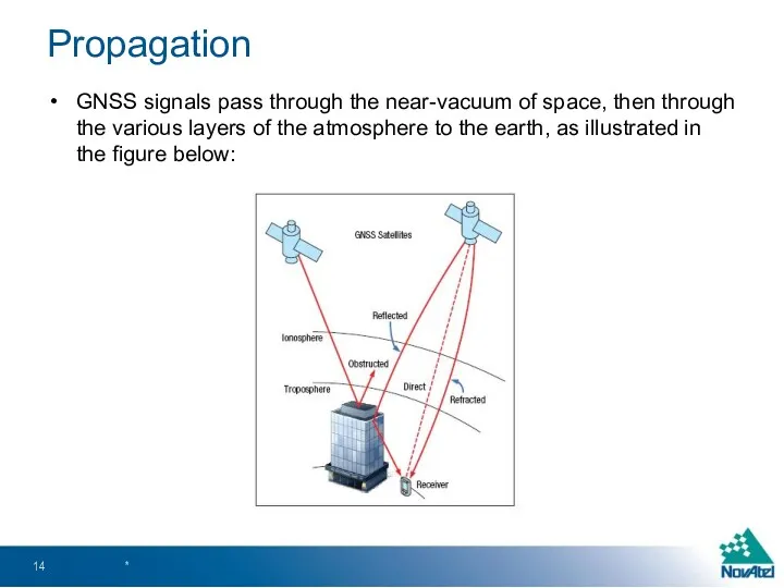
GNSS signals pass through the near-vacuum of space, then through the
Propagation
GNSS signals pass through the near-vacuum of space, then through the
Propagation
To determine accurate positions, we need to know the range to
Propagation
To determine accurate positions, we need to know the range to
Propagation
The ionosphere contributes to most of the atmospheric error. It resides
Propagation
The ionosphere contributes to most of the atmospheric error. It resides
Propagation
Signals can be reflected on the way to the receiver. This
Propagation
Signals can be reflected on the way to the receiver. This
Reception
Receivers need at least 4 satellites to obtain a position. If
Reception
Receivers need at least 4 satellites to obtain a position. If
Reception
For each satellite tracked, the receiver determines the propagation time
The above
Reception
For each satellite tracked, the receiver determines the propagation time
The above
Computation
Range measurments from 4 satellites are needed to determine position
For each
Computation
Range measurments from 4 satellites are needed to determine position
For each
Computation
In a two-dimentional world, here is how position calculation works:
If receiver
Computation
In a two-dimentional world, here is how position calculation works:
If receiver
Due to receiver clock error, the intersecting points between the range
Due to receiver clock error, the intersecting points between the range
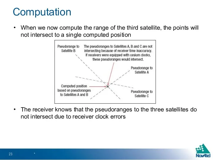
When we now compute the range of the third satellite, the
When we now compute the range of the third satellite, the
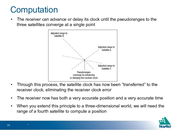
The receiver can advance or delay its clock until the pseudoranges
The receiver can advance or delay its clock until the pseudoranges
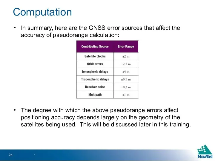
In summary, here are the GNSS error sources that affect the
In summary, here are the GNSS error sources that affect the
GNSS Satellite Systems
*
GNSS Satellite Systems
*
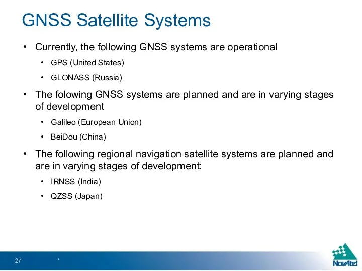
Currently, the following GNSS systems are operational
GPS (United States)
GLONASS (Russia)
The folowing
Currently, the following GNSS systems are operational
GPS (United States)
GLONASS (Russia)
The folowing
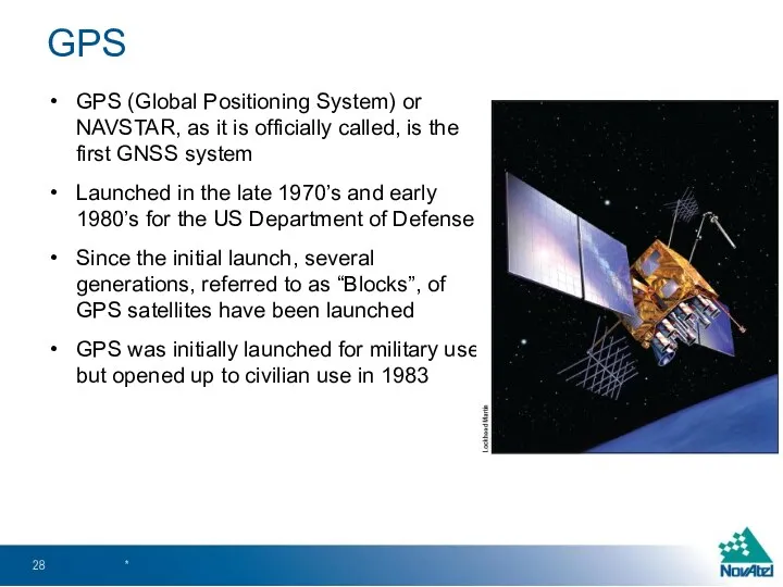
GPS (Global Positioning System) or NAVSTAR, as it is officially called,
GPS (Global Positioning System) or NAVSTAR, as it is officially called,
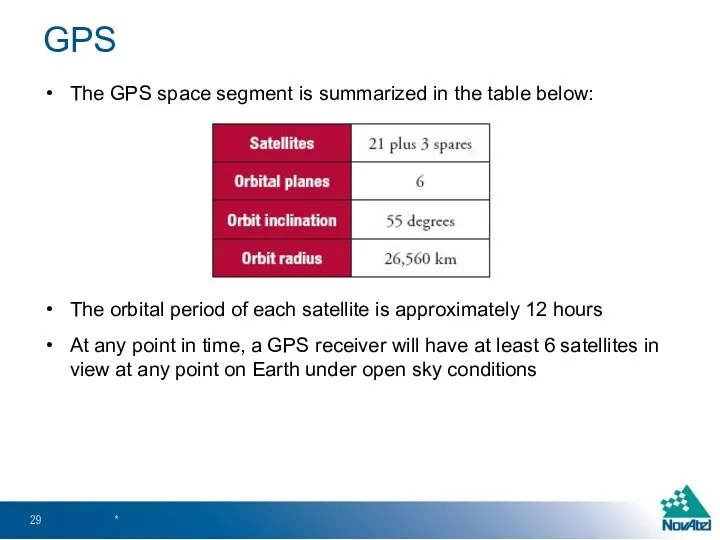
The GPS space segment is summarized in the table below:
The orbital
The GPS space segment is summarized in the table below:
The orbital
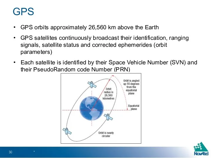
GPS orbits approximately 26,560 km above the Earth
GPS satellites continuously broadcast
GPS orbits approximately 26,560 km above the Earth
GPS satellites continuously broadcast
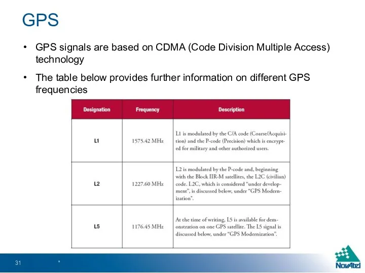
GPS signals are based on CDMA (Code Division Multiple Access) technology
The
GPS signals are based on CDMA (Code Division Multiple Access) technology
The
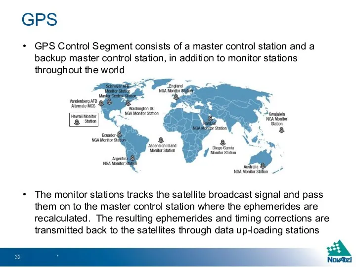
GPS Control Segment consists of a master control station and a
GPS Control Segment consists of a master control station and a
GPS space segment modernization has included new signals, as well as
GPS space segment modernization has included new signals, as well as
A new GPS L5 frequency (1176.45 MHz) is slowly being added
A new GPS L5 frequency (1176.45 MHz) is slowly being added
GLONASS (Global Navigation Satellite System) was developed by the Soviet Union
GLONASS (Global Navigation Satellite System) was developed by the Soviet Union
The GLONASS constellation provides visibility to a variable number of satellites,
The GLONASS constellation provides visibility to a variable number of satellites,
The GLONASS control segment consists of the system control center and
The GLONASS control segment consists of the system control center and
GLONASS satellites each transmit on slightly different L1 and L2 frequencies
GLONASS
GLONASS satellites each transmit on slightly different L1 and L2 frequencies
GLONASS
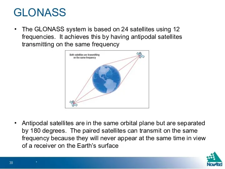
The GLONASS system is based on 24 satellites using 12 frequencies.
The GLONASS system is based on 24 satellites using 12 frequencies.
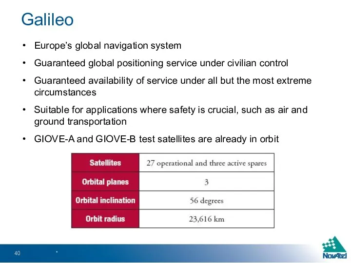
Europe’s global navigation system
Guaranteed global positioning service under civilian control
Guaranteed availability
Europe’s global navigation system
Guaranteed global positioning service under civilian control
Guaranteed availability
Once the constellation is operational, Galileo navigation signals will provide coverage
Once the constellation is operational, Galileo navigation signals will provide coverage
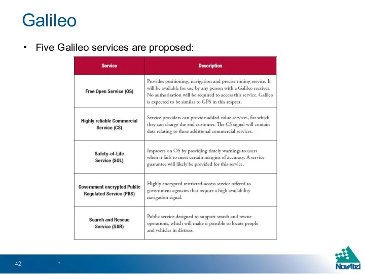
Five Galileo services are proposed:
*
Galileo
Five Galileo services are proposed:
*
Galileo
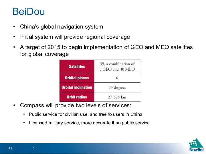
China’s global navigation system
Initial system will provide regional coverage
A target of
China’s global navigation system
Initial system will provide regional coverage
A target of
IRNSS (India Regional Navigation Satellite System, India)
Satellite system to provide regional
IRNSS (India Regional Navigation Satellite System, India)
Satellite system to provide regional
Advanced GNSS Concepts
Advanced GNSS Concepts
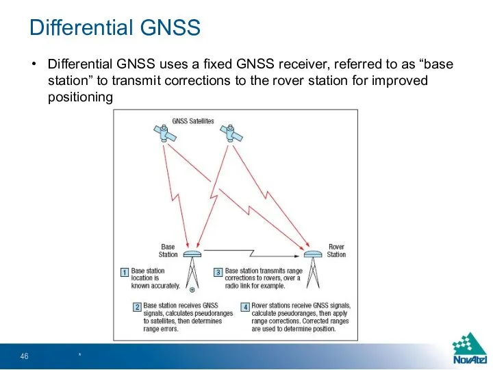
Differential GNSS uses a fixed GNSS receiver, referred to as “base
Differential GNSS uses a fixed GNSS receiver, referred to as “base
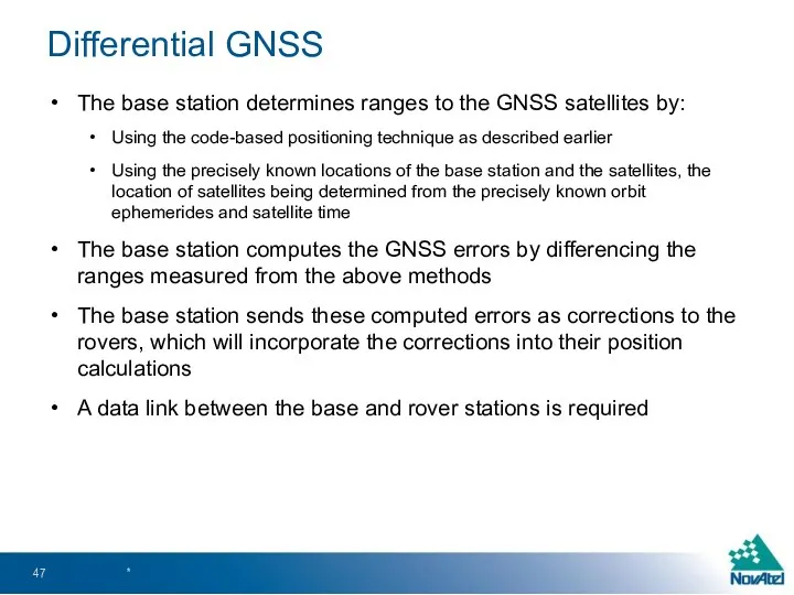
The base station determines ranges to the GNSS satellites by:
Using the
The base station determines ranges to the GNSS satellites by:
Using the
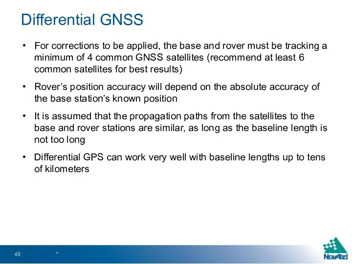
For corrections to be applied, the base and rover must be
For corrections to be applied, the base and rover must be
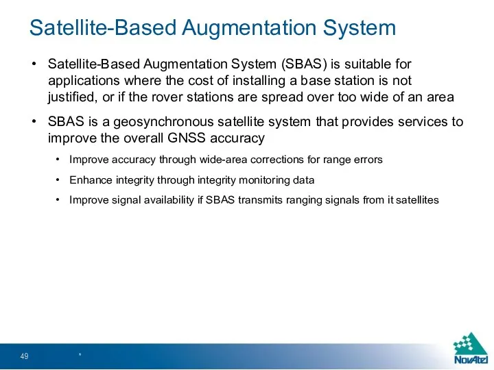
Satellite-Based Augmentation System (SBAS) is suitable for applications where the cost
Satellite-Based Augmentation System (SBAS) is suitable for applications where the cost

Reference stations receive GNSS signals and forwards them to master station
Master
Reference stations receive GNSS signals and forwards them to master station
Master
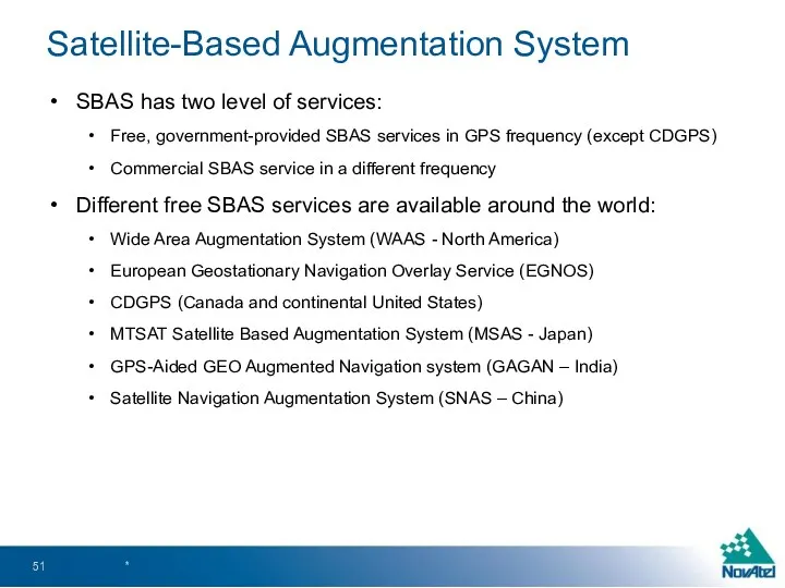
SBAS has two level of services:
Free, government-provided SBAS services in GPS
SBAS has two level of services:
Free, government-provided SBAS services in GPS
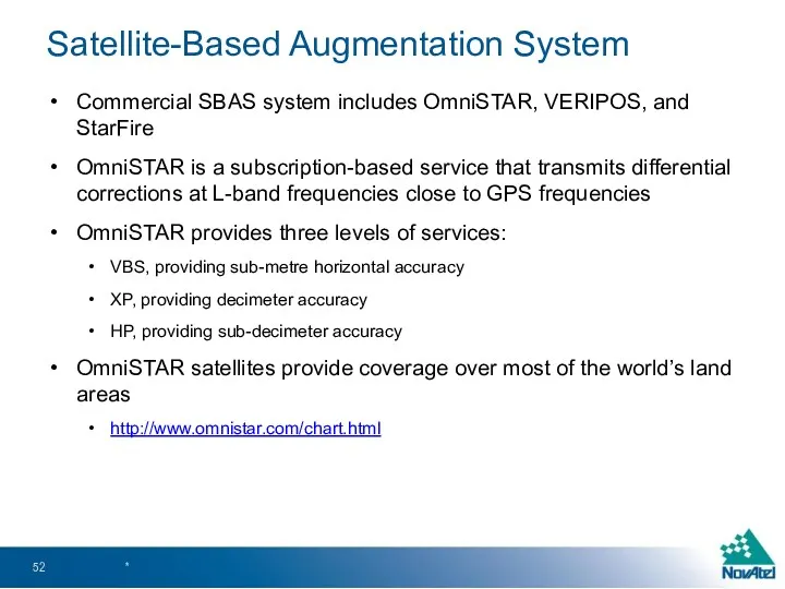
Commercial SBAS system includes OmniSTAR, VERIPOS, and StarFire
OmniSTAR is a subscription-based
Commercial SBAS system includes OmniSTAR, VERIPOS, and StarFire
OmniSTAR is a subscription-based
Real-Time Kinematic (RTK)
Carrier-based ranging that provides more accurate positioning than through
Real-Time Kinematic (RTK)
Carrier-based ranging that provides more accurate positioning than through
The range is calculated by determining the number of carrier cycles
The range is calculated by determining the number of carrier cycles
Dilution of Precision (DOP)
DOP is a numeric value that represents the
Dilution of Precision (DOP)
DOP is a numeric value that represents the
Dilution of Precision (DOP)
A good DOP means the satellites in view
Dilution of Precision (DOP)
A good DOP means the satellites in view
DOP can be expressed as a number of separate elements:
HDOP –
DOP can be expressed as a number of separate elements:
HDOP –
Combined GNSS/Inertial Navigation Systems
Combination of GNSS and INS will give continuous
Combined GNSS/Inertial Navigation Systems
Combination of GNSS and INS will give continuous
INS uses rotation and acceleration information from an Inertial Measurement Unit
INS uses rotation and acceleration information from an Inertial Measurement Unit
GNSS Data Post-Processing
For applications where real-time solution is not necessary, raw
GNSS Data Post-Processing
For applications where real-time solution is not necessary, raw
GNSS Applications and Equipment
*
GNSS Applications and Equipment
*
Applications
Some common GNSS Applications include:
Transportation
Timing
Machine Control
Marine
Surveying
Defence
Port Automation
*
Applications
Some common GNSS Applications include:
Transportation
Timing
Machine Control
Marine
Surveying
Defence
Port Automation
*
Transportation
Portable navigation devices
Air, marine, and ground based vehicle navigation
*
www.boeing.com
Transportation
Portable navigation devices
Air, marine, and ground based vehicle navigation
*
www.boeing.com
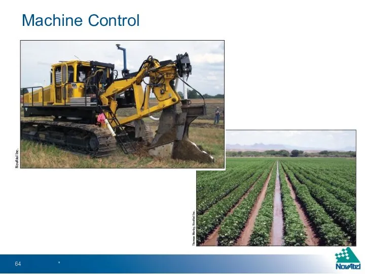
Machine Control
*
Machine Control
*
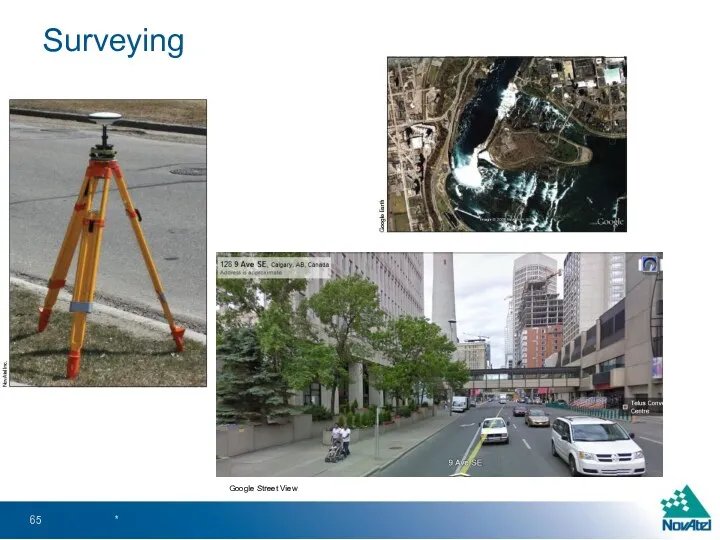
Surveying
*
Google Street View
Surveying
*
Google Street View
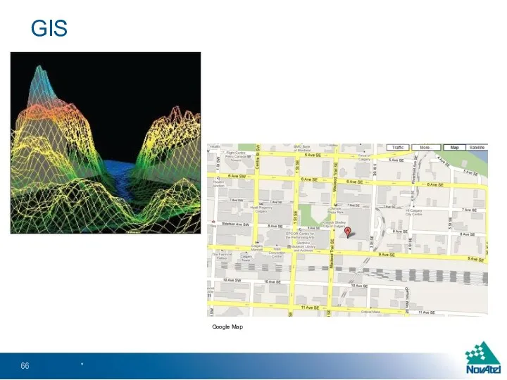
GIS
*
Google Map
GIS
*
Google Map
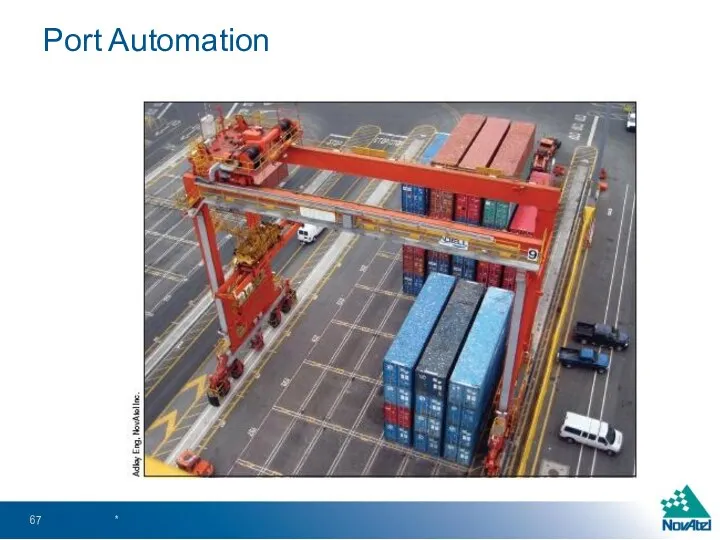
Port Automation
*
Port Automation
*
Defence
*
Defence
*
Equipment
There are different types of GNSS equipment available depending on the
Equipment
There are different types of GNSS equipment available depending on the
 Guide to Yatu color mixing system
 Брейн-ринг по теме АЛГЕБРА ЛОГИКИ
 ОП.08 Использование ПП для торговых операций, презентация Назначение программного продукта. Структура 1С: Предприятие
 Роутеры. Wi-Fi роутер
 Бренд-персонаж в игровой индустрии
 Использование компьютера в обучении детей с нарушением слуха
 Есептеу жүйесі
 Организация потоков в Java. (Лекции 8)
 Інтерактивний веб-сайт служби експрес-доставки вантажів
 Структура компьютера. Понятие вычислительной системы
 ლექციათა კურსი ობიექტზე ორიენტირებული დაპროგრამება 1 (C++)
 Компьютерлік желілері
 Операционная система. Назначение и основные функции
 Графический редактор Paint
 Конспект урока информатики на тему Создание графических изображений
 Электронная почта и другие сервисы сети Интернет
 OSINT(Open Source Intelligency)
 Геймінг – це гра у відеоігри на колективних турнірах
 Основные компоненты ПК
 Налаштування параметрів та перетворення формату готового зображення
 Виды памяти в ТСИ
 Библиографическое описание разных видов документов
 Классификация ЧМ интерфейсов
 Своя игра. Викторина. Шаблон
 Алфавитный подход к определению количества информации. Единицы измерения информации.
 Логические основы компьютеров
 Введение HTML / CSS
 Әлеуметтік желілердің қазіргі жастардың дүниетанымына тигізетін әсері