- Cmpe 466 computer graphics. Computer graphics hardware. (Сhapter 2)

Содержание
- 2. Video display devices
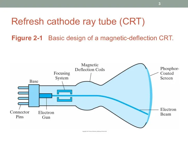
- 3. Refresh cathode ray tube (CRT) Figure 2-1 Basic design of a magnetic-deflection CRT.
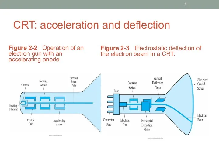
- 4. CRT: acceleration and deflection Figure 2-2 Operation of an electron gun with an accelerating anode. Figure
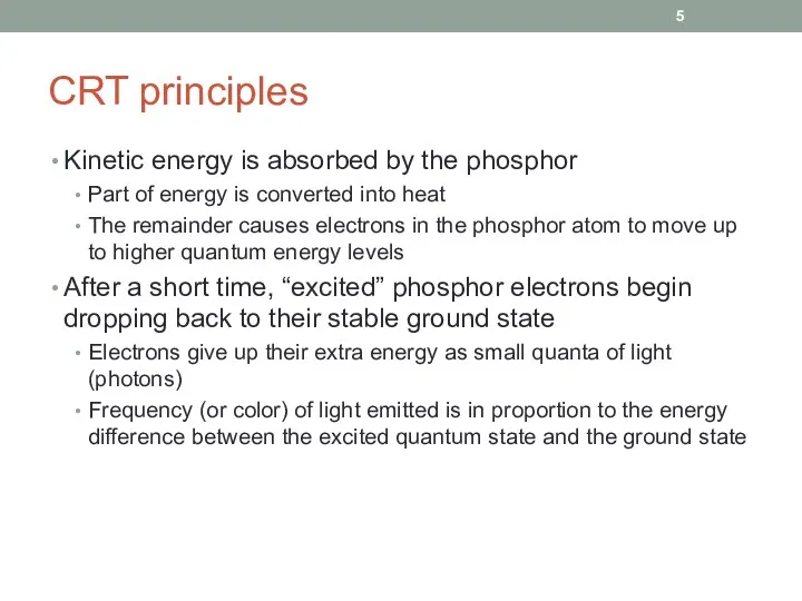
- 5. CRT principles Kinetic energy is absorbed by the phosphor Part of energy is converted into heat
- 6. Phosphor spots Figure 2-4 Intensity distribution of an illuminated phosphor spot on a CRT screen. Figure
- 7. Resolution and size Maximum number of points that can be displayed without overlap on a CRT
- 8. Raster-scan display Electron beam is swept across the screen, one row at a time, from top
- 9. Frame buffer, pixels, and bit planes Picture definition is stored in a memory area called the
- 10. Refresh rate As each screen refresh takes place, we tend to see each frame as a
- 11. Color CRT (RGB) monitors Color monitors use a combination of phosphors that emit different colored light
- 12. Flat-panel plasma displays Figure 2-10 Basic design of a plasma-panel display device. Mixture of gases that
- 13. Flat-panel TFEL displays Figure 2-11 Basic design of a thin-film electroluminescent display device. The region is
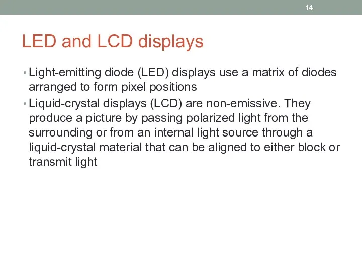
- 14. LED and LCD displays Light-emitting diode (LED) displays use a matrix of diodes arranged to form
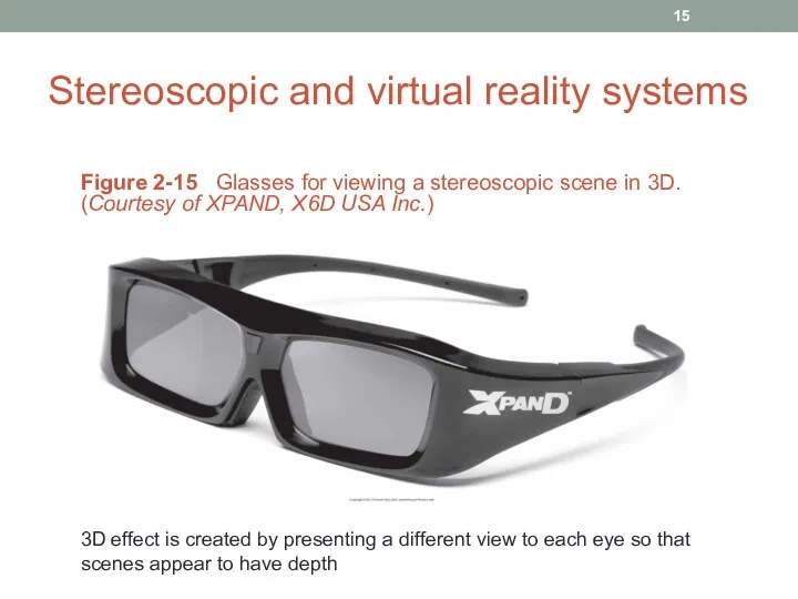
- 15. Stereoscopic and virtual reality systems Figure 2-15 Glasses for viewing a stereoscopic scene in 3D. (Courtesy
- 16. Stereoscopic effect on a raster system On a raster system, we can display each of the
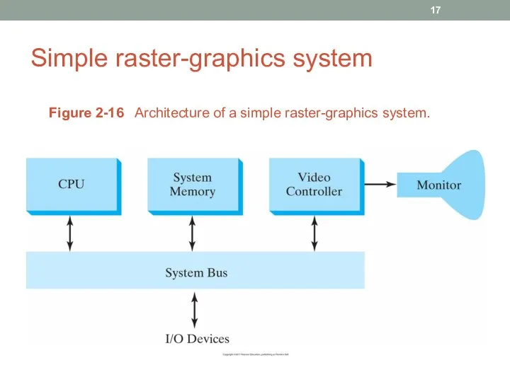
- 17. Simple raster-graphics system Figure 2-16 Architecture of a simple raster-graphics system.
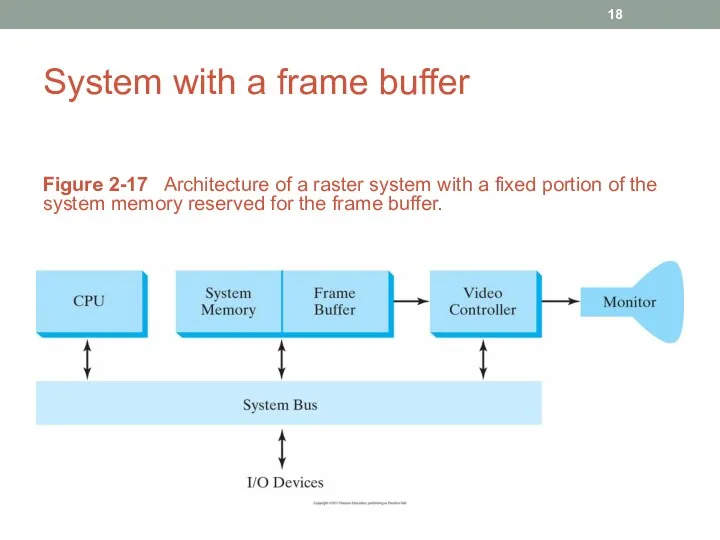
- 18. System with a frame buffer Figure 2-17 Architecture of a raster system with a fixed portion
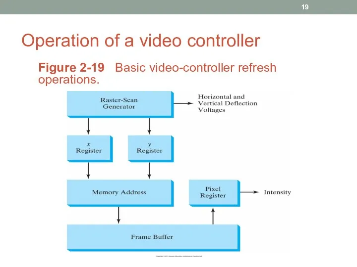
- 19. Operation of a video controller Figure 2-19 Basic video-controller refresh operations.
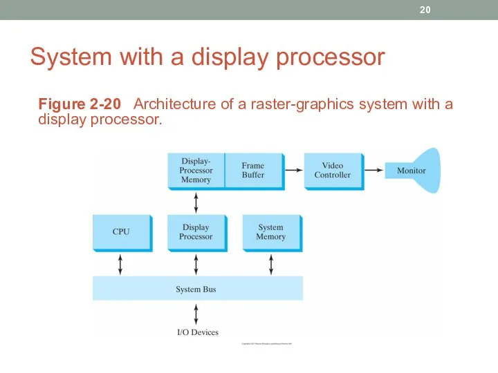
- 20. System with a display processor Figure 2-20 Architecture of a raster-graphics system with a display processor.
- 21. Some notes It is possible to retrieve pixel values from different memory areas (multiple frame buffers)
- 22. Input and hard-copy devices
- 23. Input devices Keyboards, button boxes, and dials Mouse devices Trackballs (2D) which can be rotated and
- 25. Скачать презентацию
Video display devices
Video display devices
Refresh cathode ray tube (CRT)
Figure 2-1 Basic design of a magnetic-deflection
Refresh cathode ray tube (CRT)
Figure 2-1 Basic design of a magnetic-deflection
CRT: acceleration and deflection
Figure 2-2 Operation of an electron gun with
CRT: acceleration and deflection
Figure 2-2 Operation of an electron gun with
CRT principles
Kinetic energy is absorbed by the phosphor
Part of energy is
CRT principles
Kinetic energy is absorbed by the phosphor
Part of energy is
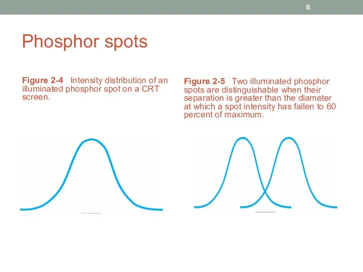
Phosphor spots
Figure 2-4 Intensity distribution of an illuminated phosphor spot on
Phosphor spots
Figure 2-4 Intensity distribution of an illuminated phosphor spot on
Resolution and size
Maximum number of points that can be displayed without
Resolution and size
Maximum number of points that can be displayed without
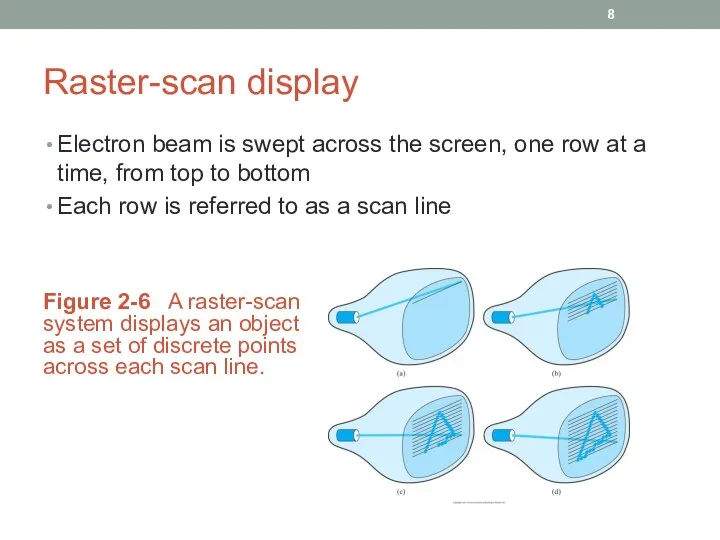
Raster-scan display
Electron beam is swept across the screen, one row at
Raster-scan display
Electron beam is swept across the screen, one row at
Frame buffer, pixels, and bit planes
Picture definition is stored in a
Frame buffer, pixels, and bit planes
Picture definition is stored in a
Refresh rate
As each screen refresh takes place, we tend to see
Refresh rate
As each screen refresh takes place, we tend to see
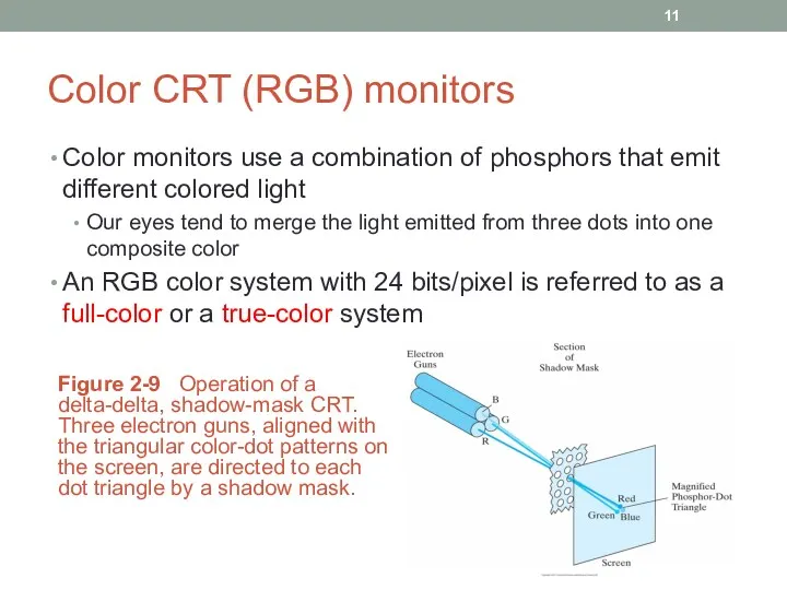
Color CRT (RGB) monitors
Color monitors use a combination of phosphors that
Color CRT (RGB) monitors
Color monitors use a combination of phosphors that
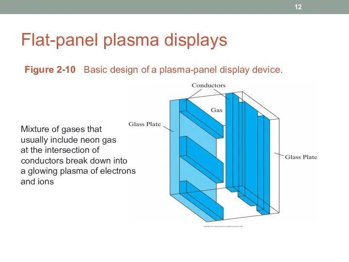
Flat-panel plasma displays
Figure 2-10 Basic design of a plasma-panel display device.
Mixture
Flat-panel plasma displays
Figure 2-10 Basic design of a plasma-panel display device.
Mixture
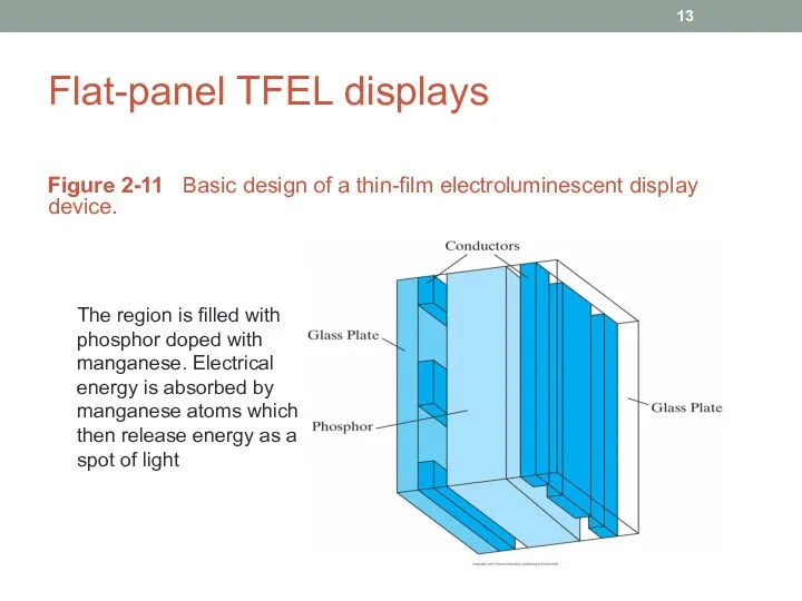
Flat-panel TFEL displays
Figure 2-11 Basic design of a thin-film electroluminescent display
Flat-panel TFEL displays
Figure 2-11 Basic design of a thin-film electroluminescent display
LED and LCD displays
Light-emitting diode (LED) displays use a matrix of
LED and LCD displays
Light-emitting diode (LED) displays use a matrix of
Stereoscopic and virtual reality systems
Figure 2-15 Glasses for viewing a stereoscopic
Stereoscopic and virtual reality systems
Figure 2-15 Glasses for viewing a stereoscopic
Stereoscopic effect on a raster system
On a raster system, we can
Stereoscopic effect on a raster system
On a raster system, we can
Simple raster-graphics system
Figure 2-16 Architecture of a simple raster-graphics system.
Simple raster-graphics system
Figure 2-16 Architecture of a simple raster-graphics system.
System with a frame buffer
Figure 2-17 Architecture of a raster system
System with a frame buffer
Figure 2-17 Architecture of a raster system
Operation of a video controller
Figure 2-19 Basic video-controller refresh operations.
Operation of a video controller
Figure 2-19 Basic video-controller refresh operations.
System with a display processor
Figure 2-20 Architecture of a raster-graphics system
System with a display processor
Figure 2-20 Architecture of a raster-graphics system
Some notes
It is possible to retrieve pixel values from different memory
Some notes
It is possible to retrieve pixel values from different memory
Input and hard-copy devices
Input and hard-copy devices
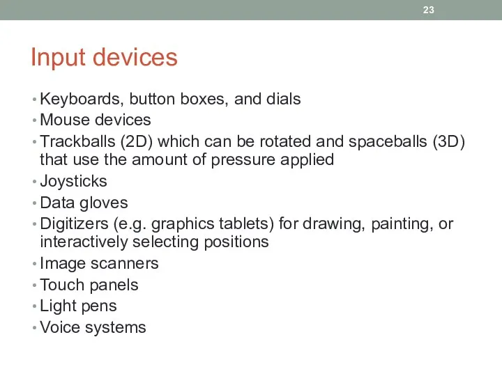
Input devices
Keyboards, button boxes, and dials
Mouse devices
Trackballs (2D) which can be
Input devices
Keyboards, button boxes, and dials
Mouse devices
Trackballs (2D) which can be
Похожие презентации
 Управление промышленными мехатронными системами
 Диаграммы реализации
 Базы данных и информационные системы
 CRM-системы в страховании
 Цифровая обработка сигналов
 Язык программирования Java
 Создание газеты в программе Microsoft Office Publisher
 Тезаурус Анти-спам. Антивирусная программа
 Интерактивная компьютерная графика. Часть 1-3 (растеризация)
 Уведення даних до комірок: текст, число. (Урок 18. 7 клас)
 Правила оформления отчетов
 Роль поисковой системы в обучении иностранным языкам
 Поняття звіту. Автоматичне створення звіту
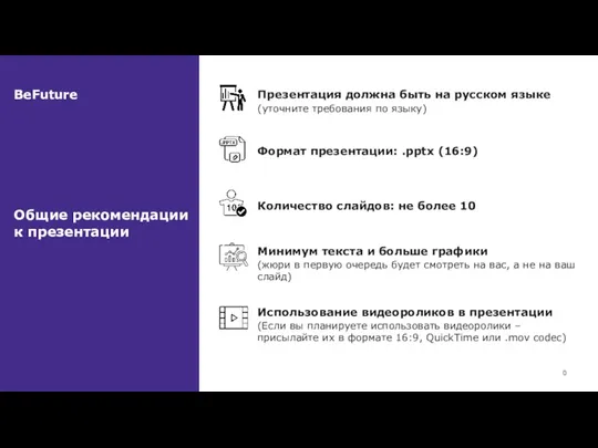 Общие рекомендации к презентации
 ОБЪЕКТ И ЕГО ХАРАКТЕРИСТИКА
 Электронные системы тестирования
 Unit-тестирование в Java
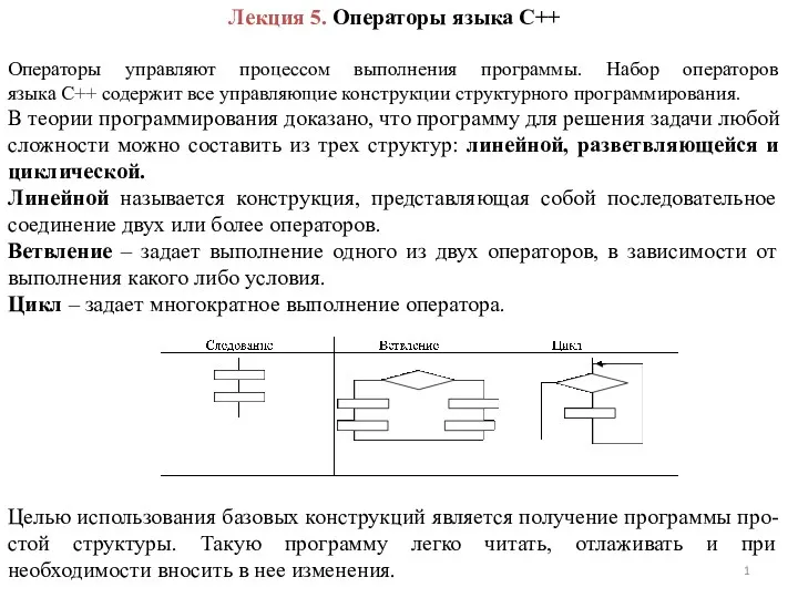 Операторы языка С++. Лекция 5
 Программирование на языке Python. §62. Массивы. 10 класс
 Программное обеспечение. § 35. Введение
 Портал государственных и муниципальных услуг Московской области
 Защита информации. Термины, понятия, определения. Тест
 Краткий обзор существующей инфраструктуры электронного правительства в Санкт-Петербурге
 Графики и диаграммы. Наглядное представление процессов изменения величин
 Первый в мире сайт и браузер
 КВН-урок
 Системы перевода и распознования текста