- Diagnostic tool introduction

Содержание
- 2. Index Diagnostic tool Appearance/Measurement Features Connection method Function overview ECU version Read DTC ECU flash Record
- 3. Diagnostic tool Appearance/Measurement H W: Width= 90mm L: Length= 145mm H: Height=30mm * Specification may subject
- 4. This hand-held diagnostic device is made for all Keeway EFi vehicles. It can diagnose the problem
- 5. Engine control unit (ECU) The ECU for managing the Cylinder 3 & 4 is located near
- 6. Connection method Diagnosing the problem of vehicle Recording the parameter when riding Changing the mapping of
- 7. There are three modes that the EFi diagnostic tools are connected to PC: 1. Firmware upgrade:
- 8. Press and hold the OK button Connect to the USB and you can see the system
- 9. Connection to the bike Before connection, please make sure: Side stand and in neutral gear, Engine
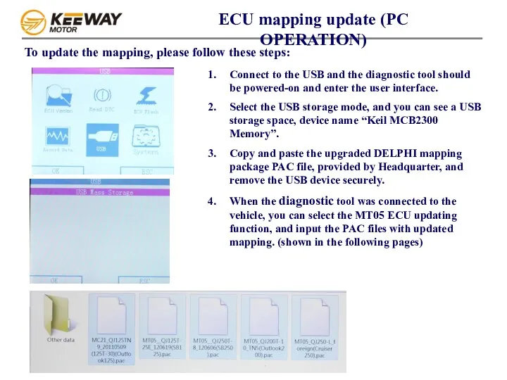
- 10. ECU mapping update (PC OPERATION) To update the mapping, please follow these steps: Connect to the
- 11. 1. Connect the tool to the bike, select the ECU flash function 2. Select MT05 flash
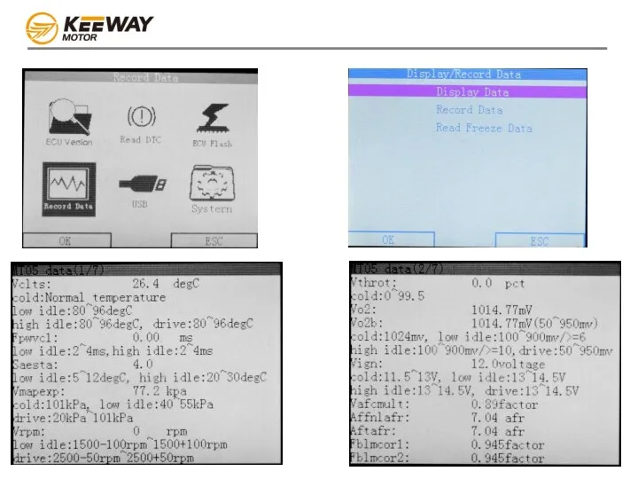
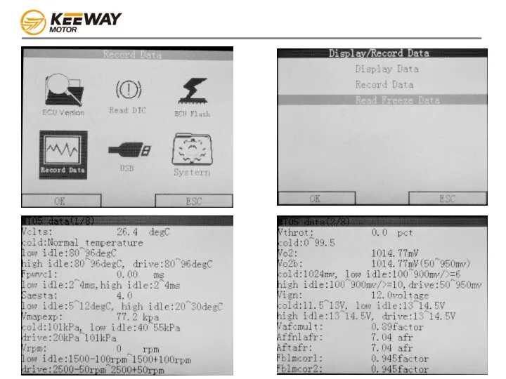
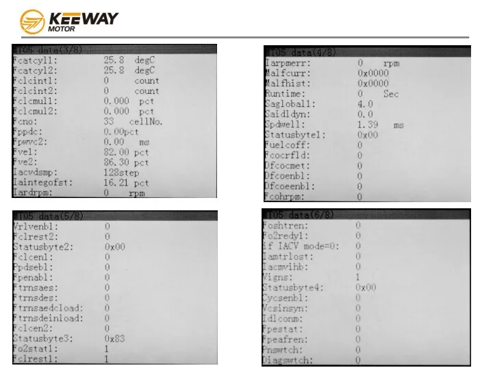
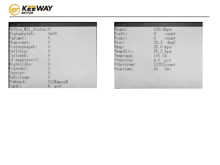
- 12. Data stream mode(recording data for developers’ analysis) 1. Connect the tool to the bike, select the
- 25. Скачать презентацию
Index
Diagnostic tool Appearance/Measurement
Features
Connection method
Function overview
ECU version
Read DTC
ECU flash
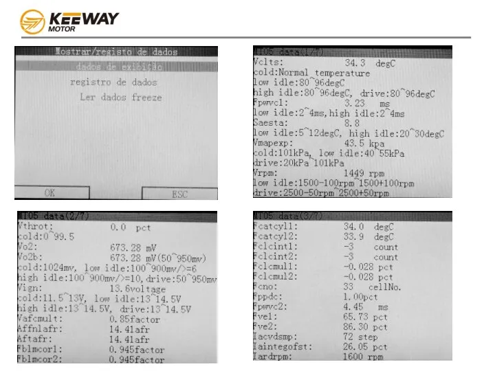
Record data
USB connection
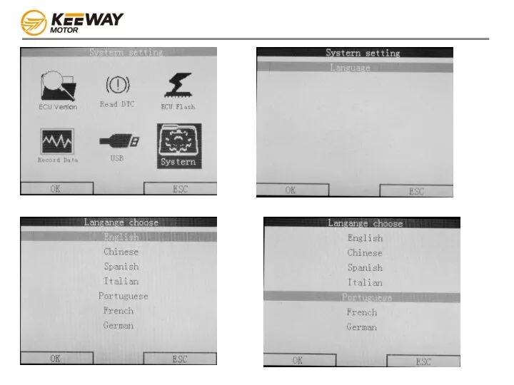
System
Index
Diagnostic tool Appearance/Measurement
Features
Connection method
Function overview
ECU version
Read DTC
ECU flash
Record data
USB connection
System
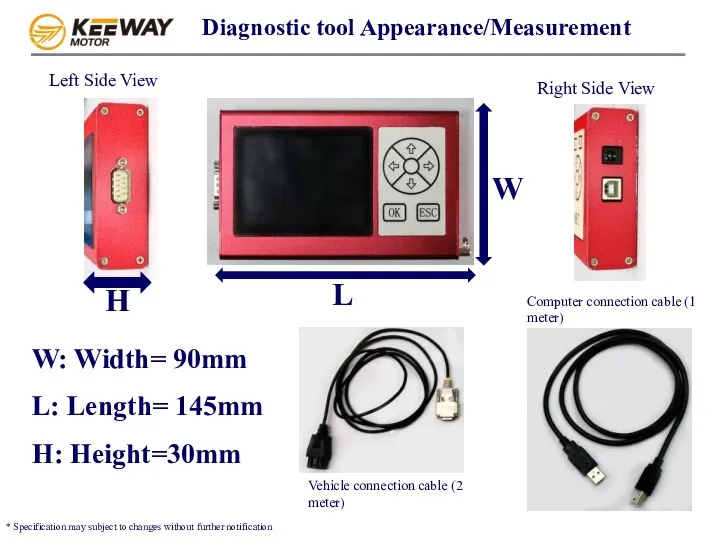
Diagnostic tool Appearance/Measurement
H
W: Width= 90mm
L: Length= 145mm
H: Height=30mm
* Specification may subject
Diagnostic tool Appearance/Measurement
H
W: Width= 90mm
L: Length= 145mm
H: Height=30mm
* Specification may subject
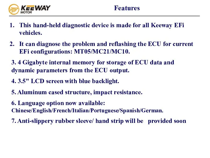
This hand-held diagnostic device is made for all Keeway EFi vehicles.
It can
This hand-held diagnostic device is made for all Keeway EFi vehicles.
It can
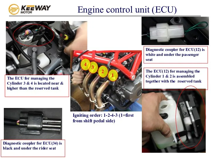
Engine control unit (ECU)
The ECU for managing the Cylinder 3 &
Engine control unit (ECU)
The ECU for managing the Cylinder 3 &
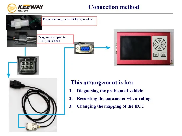
Connection method
Diagnosing the problem of vehicle
Recording the parameter when riding
Changing
Connection method
Diagnosing the problem of vehicle
Recording the parameter when riding
Changing
There are three modes that the EFi diagnostic tools are connected
There are three modes that the EFi diagnostic tools are connected
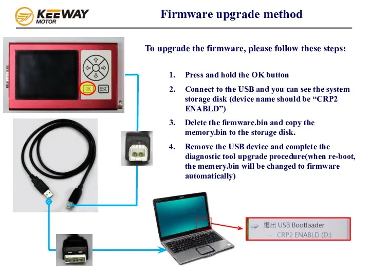
Press and hold the OK button
Connect to the USB and you
Press and hold the OK button
Connect to the USB and you
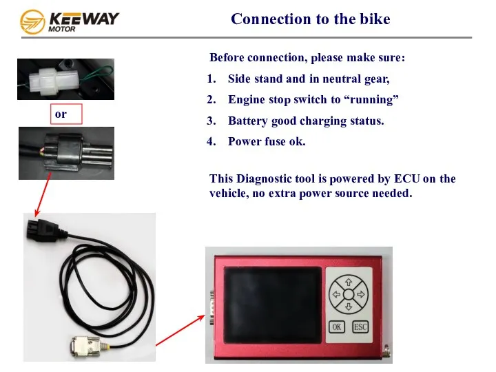
Connection to the bike
Before connection, please make sure:
Side stand and
Connection to the bike
Before connection, please make sure:
Side stand and
ECU mapping update (PC OPERATION)
To update the mapping, please follow these
ECU mapping update (PC OPERATION)
To update the mapping, please follow these
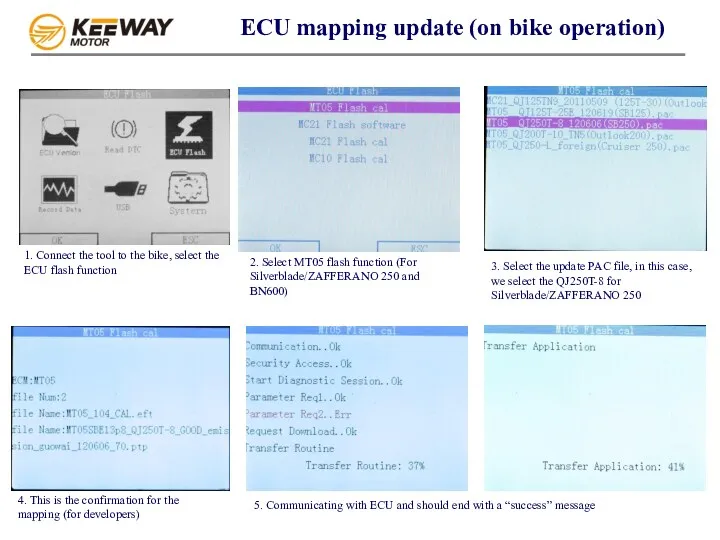
1. Connect the tool to the bike, select the ECU flash
1. Connect the tool to the bike, select the ECU flash

Data stream mode(recording data for developers’ analysis)
1. Connect the tool to
Data stream mode(recording data for developers’ analysis)
1. Connect the tool to

 Виды контента. Занятие №10 Основатель
 Сравнительный анализ антивирусных программ
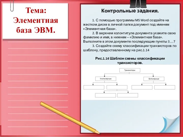 Элементная база ЭВМ
 Дети в интернете. Викторина для учащихся начальных классов
 PR органов государственной власти
 CSS 3. Cascading Style Sheets
 Презентация Логика. Тренировочные задания ЕГЭ
 Первая пара. Динамическое пр-е и рекурсия
 Виды Баз Данных
 Словарная работа по теме Интернет.
 Программалық жасақтаманы таңдау
 Мониторинг состояния московского книжного рынка
 Онлайн-сервисы и пространство в сети Интернет
 Урок информатики в 5 классе на тему: Метод координат
 Петрохимические программы. (Лекция 7)
 Аватария
 Oxyfuel Cutting Routine
 Правильное место для торговли бинарными опционами
 Система Ладошки
 Создание анимированных сорбонок для начальной школы
 Язык программирования Pascal. Основные понятия
 Устройство компьютерной сети
 Итераторы, генераторы и декораторы. Python 5.0
 Характеристика специализированных изданий
 Обработка информации. Разнообразие задач обработки информации
 История развития вычислительной техники
 Своя игра по информатике и истории для старшеклассников
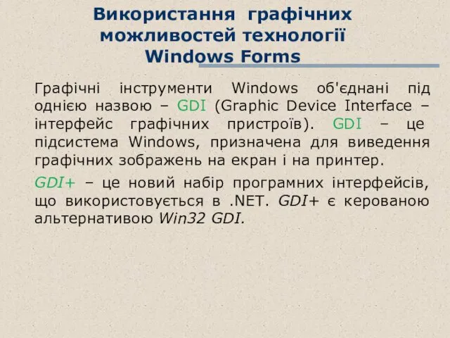 Використання графічних можливостей технології Windows Forms