- Мікропроцесорна техніка. PSoC’s Routing Resources Цифрова частина системи

Содержание
- 2. Цифрова частина системи Digital PSoC Blocks Counter PWM Timer PSoC’s Routing Resources
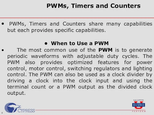
- 3. PWMs, Timers and Counters PWMs, Timers and Counters share many capabilities but each provides specific capabilities.
- 4. PWMs, Timers and Counters When to Use a Counter A Counter component is better used in
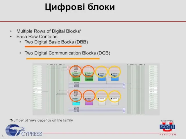
- 5. Цифрові блоки Multiple Rows of Digital Blocks* Each Row Contains: Two Digital Basic Bocks (DBB) Two
- 6. 32 total nets for Digital Routing* 16 Окремих загальних виходів* 16 Окремих загальних входів* Global Digital
- 7. Окремі загальні входи/ виходи поділяються на парні та непарні GIO = Окремі загальні входи (парні) GIE
- 8. Global nets can be used to: Під'єднання до інших Global nets Під'єднання до Pins Вхід: Вихід:
- 9. Each row of Digital Blocks has its own set of Row Interconnects 4 Input Rows and
- 10. Input Row Nets can be used for: Connection to Input Global Nets Clock Synchronization Input Row
- 11. For every digital block row, there is one Row Broadcast Net Row Broadcast Nets for Digital
- 12. Global Resources
- 13. Module Objectives At the end of this module, you should be able to: List the three
- 14. User Module Datasheets Each user module has its own datasheet contained within the PSoC Designer software
- 15. User-defined pin outs are color-coded and detailed in the project configuration datasheet. PSoC Project Configuration Datasheet
- 16. Project configuration datasheets also contain the placement and routing of user modules Project configuration datasheets are
- 17. Секція 1: Counters
- 19. Properties Counter
- 20. Row Broadcast Nets can be connected to Each other A digital block Thus, any digital block
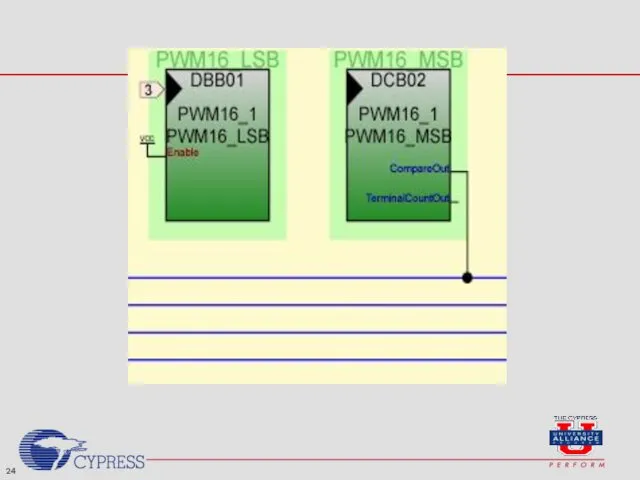
- 21. Секція 2: PWM
- 23. Properties PWM
- 25. Properties PWM
- 26. Секція 3: TIMER
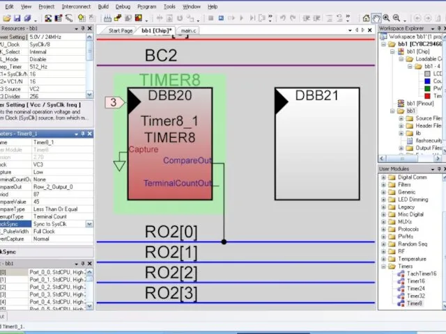
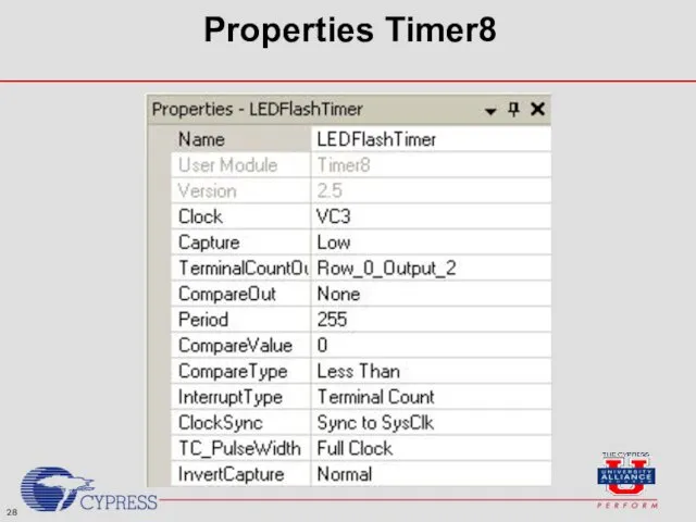
- 28. Properties Timer8
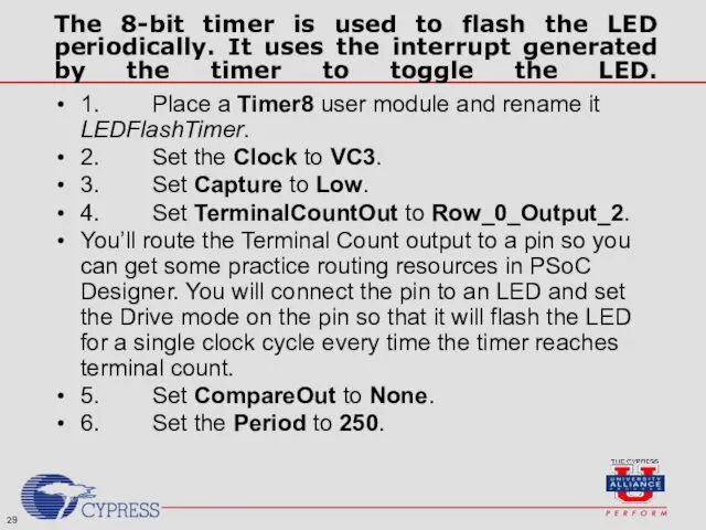
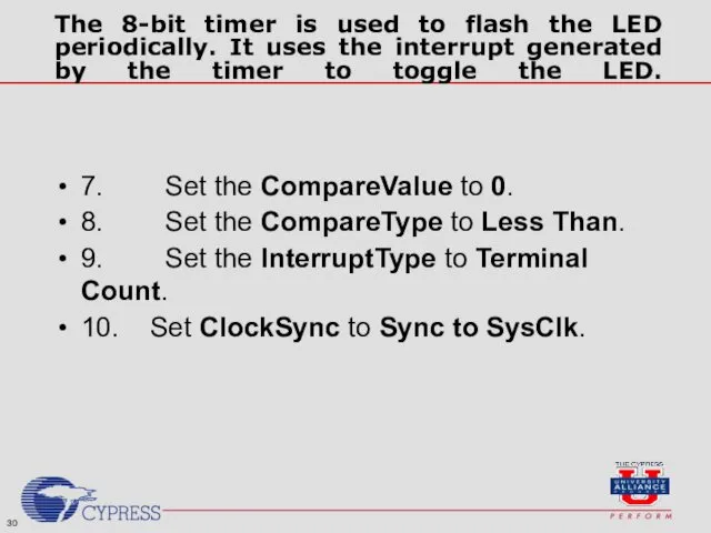
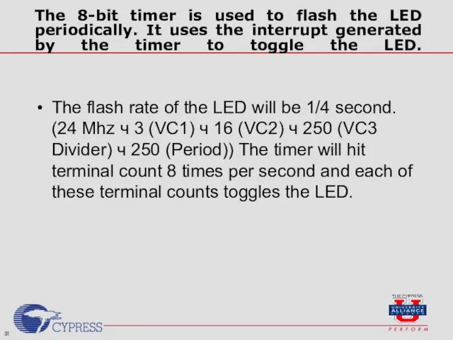
- 29. The 8-bit timer is used to flash the LED periodically. It uses the interrupt generated by
- 30. The 8-bit timer is used to flash the LED periodically. It uses the interrupt generated by
- 31. The 8-bit timer is used to flash the LED periodically. It uses the interrupt generated by
- 33. Скачать презентацию
Цифрова частина системи
Digital PSoC Blocks
Counter
PWM
Timer
PSoC’s Routing Resources
Цифрова частина системи
Digital PSoC Blocks
Counter
PWM
Timer
PSoC’s Routing Resources
PWMs, Timers and Counters
PWMs, Timers and Counters share many capabilities but
PWMs, Timers and Counters
PWMs, Timers and Counters share many capabilities but

PWMs, Timers and Counters
When to Use a Counter
A Counter component is
PWMs, Timers and Counters
When to Use a Counter
A Counter component is
Цифрові блоки
Multiple Rows of Digital Blocks*
Each Row Contains:
Two Digital Basic Bocks
Цифрові блоки
Multiple Rows of Digital Blocks*
Each Row Contains:
Two Digital Basic Bocks

32 total nets for Digital Routing*
16
Окремих
загальних
виходів*
16
Окремих
загальних
входів*
Global Digital Interconnect
*Depends
16
Окремих
загальних
виходів*
16
Окремих
загальних
входів*
Global Digital Interconnect
*Depends
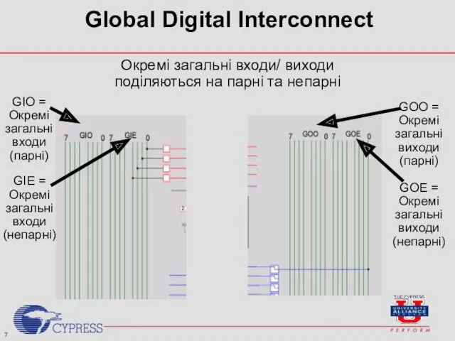
Окремі загальні входи/ виходи
поділяються на парні та непарні
GIO =
Окремі
загальні
входи
(парні)
GIE =
Окремі
загальні
входи
(непарні)
GOO
Окремі загальні входи/ виходи
поділяються на парні та непарні
GIO =
Окремі
загальні
входи
(парні)
GIE =
Окремі
загальні
входи
(непарні)
GOO
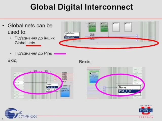
Global nets can be used to:
Під'єднання до інших Global nets
Під'єднання до
Global nets can be used to:
Під'єднання до інших Global nets
Під'єднання до
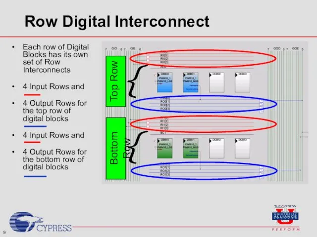
Each row of Digital Blocks has its own set of Row
Each row of Digital Blocks has its own set of Row

Input Row Nets can be used for:
Connection to Input Global Nets
Clock
Input Row Nets can be used for:
Connection to Input Global Nets
Clock

For every digital block row, there is one Row Broadcast Net
Row
For every digital block row, there is one Row Broadcast Net
Row
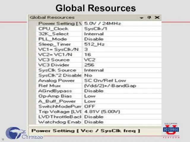
Global Resources
Global Resources
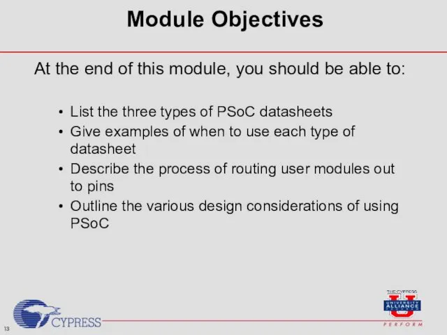
Module Objectives
At the end of this module, you should be able
Module Objectives
At the end of this module, you should be able
User Module Datasheets
Each user module has its own datasheet contained within
User Module Datasheets
Each user module has its own datasheet contained within
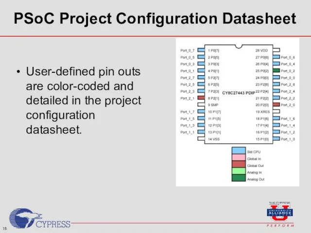
User-defined pin outs are color-coded and detailed in the project configuration
User-defined pin outs are color-coded and detailed in the project configuration
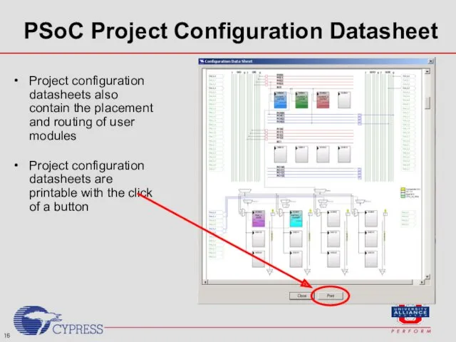
Project configuration datasheets also contain the placement and routing of user
Project configuration datasheets also contain the placement and routing of user
Секція 1:
Counters
Секція 1:
Counters
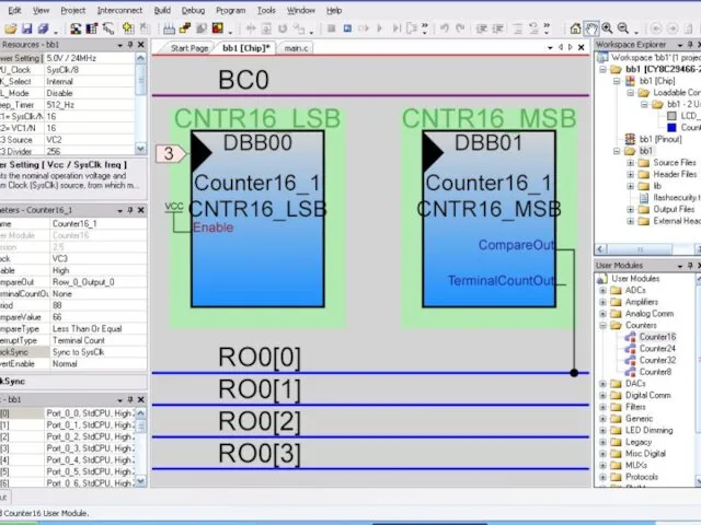

Properties Counter
Properties Counter
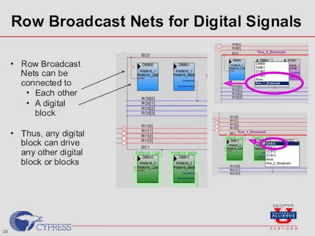
Row Broadcast Nets can be connected to
Each other
A digital block
Thus, any
Row Broadcast Nets can be connected to
Each other
A digital block
Thus, any
Секція 2:
PWM
Секція 2:
PWM
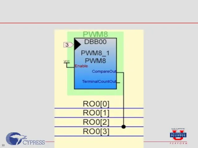
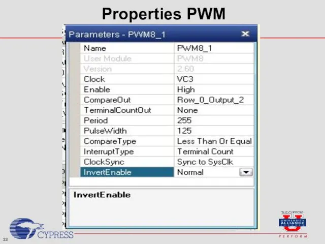
Properties PWM
Properties PWM
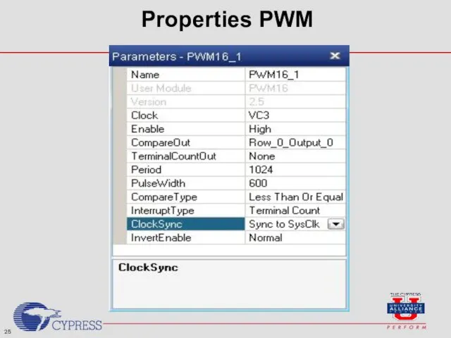
Properties PWM
Properties PWM

Секція 3:
TIMER
Секція 3:
TIMER
Properties Timer8
Properties Timer8
The 8-bit timer is used to flash the LED periodically. It
The 8-bit timer is used to flash the LED periodically. It
The 8-bit timer is used to flash the LED periodically. It
The 8-bit timer is used to flash the LED periodically. It
The 8-bit timer is used to flash the LED periodically. It
The 8-bit timer is used to flash the LED periodically. It
 Интеллектуальные информационные системы (ИИС). Лекция 7. Нечеткий логический вывод
 Информационная деятельность человека: сбор, обработка, хранение, передача, защита информации. Урок №2
 Все на поиск терминов. Компьютерный турнир
 Системы управления базами данных (СУБД) MS Access
 Мультимедийная презентация-сказкаРепкав технике оригами.
 Основные сведения о персональных компьютерах. (Тема 4)
 Устройство компьютера
 Apache Kafka
 Настройка сетевых параметров операционных систем Windows и Linux
 Типы информационных моделей. Основные этапы разработки и исследования моделей на компьютере
 Цветовые модели компьютерной графики
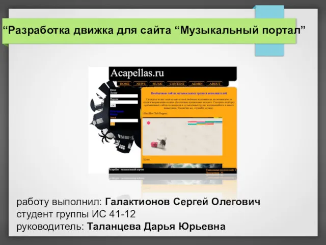 Разработка движка для сайта “Музыкальный портал”
 Диаграмма состояний. Применение языка UML при разработке информационных систем
 Графика в Pascal ABC
 Система Ладошки
 Электронное правительство
 Технологии обработки данных. Сетевые технологии обработки данных. (Лекция 8)
 Модуль 1: Установка и настройка SQL Server 2008
 Введение в C#. Новый язык от Microsoft
 Информация и информационные технологии
 Постановка задачи обеспечения информационной безопасности баз данных
 Системы управления контентом CMS (08)
 Spring Framework
 Как пройти нормоконтроль
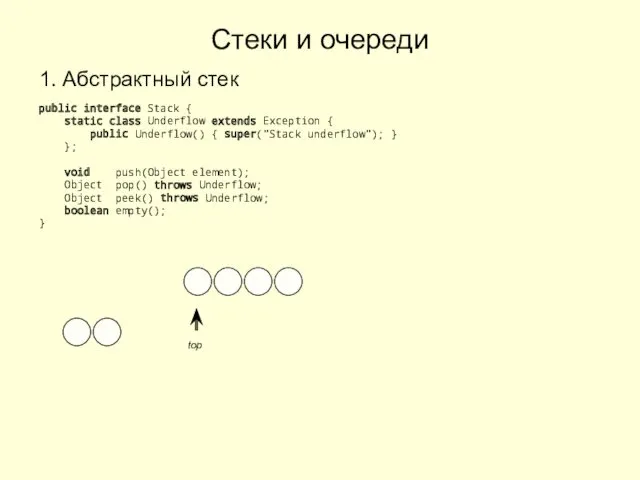 Стеки и очереди
 Подготовка к ОГЭ (информатика)
 Аддитивные технологии
 Компьютерный сленг и его использование в молодёжной среде