- Network programming

Содержание
- 2. Introduction Network Programming is one of the central tasks when developing business applications. The necessity in
- 3. Introduction Why network programming in .NET Framework? One of the first technical decisions to be made
- 4. Introduction Why network programming in .NET Framework? In fact, .NET Framework has more intrinsic support for
- 5. Introduction What can a network program do? A network program is any application that uses a
- 6. Introduction What can a network program do? In case of a browser, every Web site you
- 7. Introduction What can a network program do? Our course is largely concerned with creating network programs,
- 8. Introduction What can a network program do? Users generally trust network applications, and as such these
- 9. Introduction What can a network program do? More importantly, from a networking perspective, an application has
- 10. Introduction What can a network program do? This applies even when the Web site contains embedded
- 11. Networking Concepts and Protocols Let’s introduce some of the basic networking concepts and protocols. We start
- 12. Networking Concepts and Protocols Then we take a look at the seven layers of the OSI
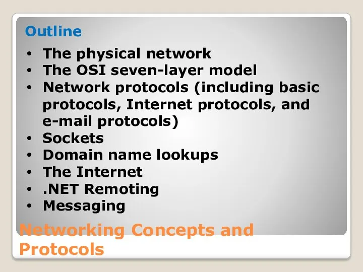
- 13. Networking Concepts and Protocols Outline The physical network The OSI seven-layer model Network protocols (including basic
- 14. The Physical Network In essence, a network is a group of computers or devices connected by
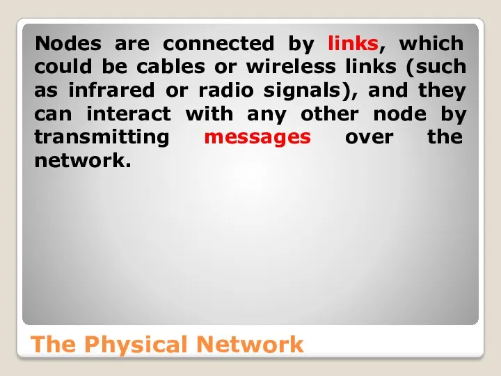
- 15. The Physical Network Nodes are connected by links, which could be cables or wireless links (such
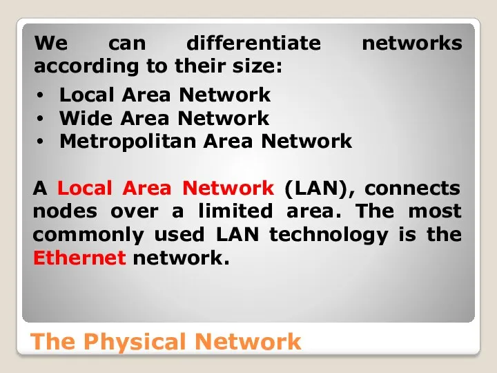
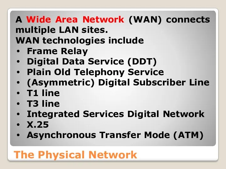
- 16. The Physical Network We can differentiate networks according to their size: Local Area Network Wide Area
- 17. The Physical Network A Wide Area Network (WAN) connects multiple LAN sites. WAN technologies include Frame
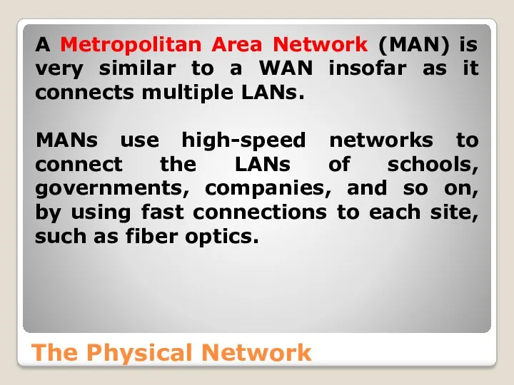
- 18. The Physical Network A Metropolitan Area Network (MAN) is very similar to a WAN insofar as
- 19. The Physical Network Backbone In discussions about networks, the term “backbone” is often used. A backbone
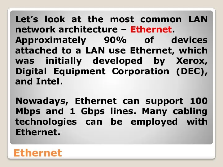
- 20. Ethernet Let’s look at the most common LAN network architecture – Ethernet. Approximately 90% of devices
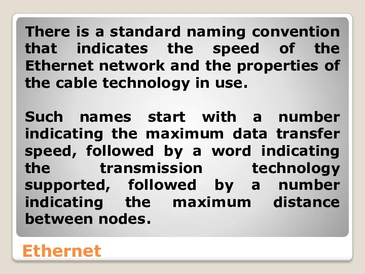
- 21. Ethernet There is a standard naming convention that indicates the speed of the Ethernet network and
- 22. Ethernet Ethernet Cables
- 23. Ethernet (CSMA/CD) Ethernet is a Carrier Sense Multiple Access/Collision Detect (CSMA/CD) network. Multiple devices are connected
- 24. Ethernet (CSMA/CD) Figure 1.
- 25. Ethernet (CSMA/CD) There is a potential problem: more than one node could attempt to send a
- 26. Ethernet (CSMA/CD) There is still, however, the possibility that two nodes, after checking that the network
- 27. Ethernet (CSMA/CD) Both nodes then halt their transmissions immediately and wait a random time interval before
- 28. Ethernet (CSMA/CD) Every node on the local network uses a Media Access Control (MAC) address for
- 29. Token Ring (IEEE 802.5) is a network architecture developed by IBM. The nodes are connected in
- 30. Figure 2 Other Network Architectures
- 31. Other Network Architectures AppleTalk is a LAN protocol developed by Apple for Apple Macintosh networks that
- 32. Physical Components An important aspect of understanding the network is knowing the hardware components. The major
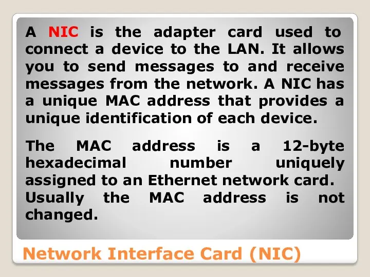
- 33. Network Interface Card (NIC) A NIC is the adapter card used to connect a device to
- 34. Network Interface Card (NIC) You can find the MAC address of a Windows machine using the
- 35. Network Interface Card (NIC) http://www.adminsub.net/mac-address-finder Figure 3
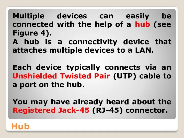
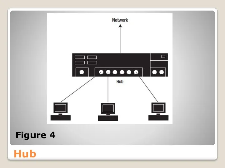
- 36. Hub Multiple devices can easily be connected with the help of a hub (see Figure 4).
- 37. Hub Figure 4
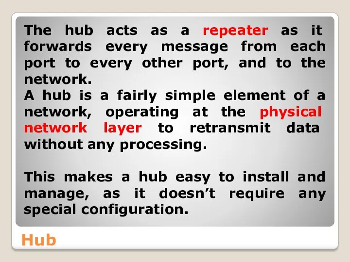
- 38. Hub The hub acts as a repeater as it forwards every message from each port to
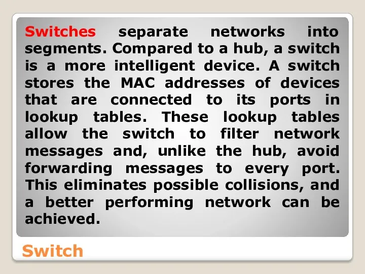
- 39. Switch Switches separate networks into segments. Compared to a hub, a switch is a more intelligent
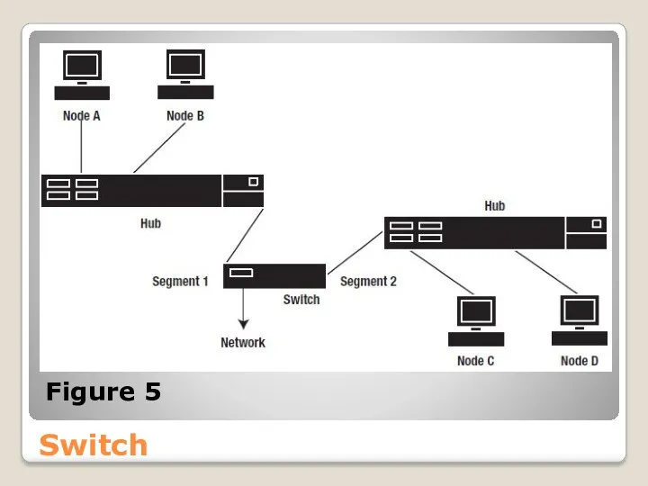
- 40. Switch As shown in Figure 5, a switch can be used to connect hubs at a
- 41. Switch Figure 5
- 42. Switch This sort of arrangement was popular in the early days, when hubs were much cheaper
- 43. Router A router is an intermediary network device that connects multiple physical networks. With many hosts,
- 44. Router ● The capability of restricting users to particular subnets offers security benefits. ● Smaller subnets
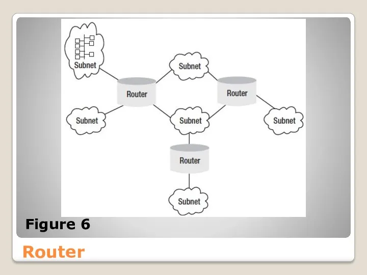
- 45. Router Figure 6
- 46. Router Note If you’re using a router in a LAN, be aware that a router isn’t
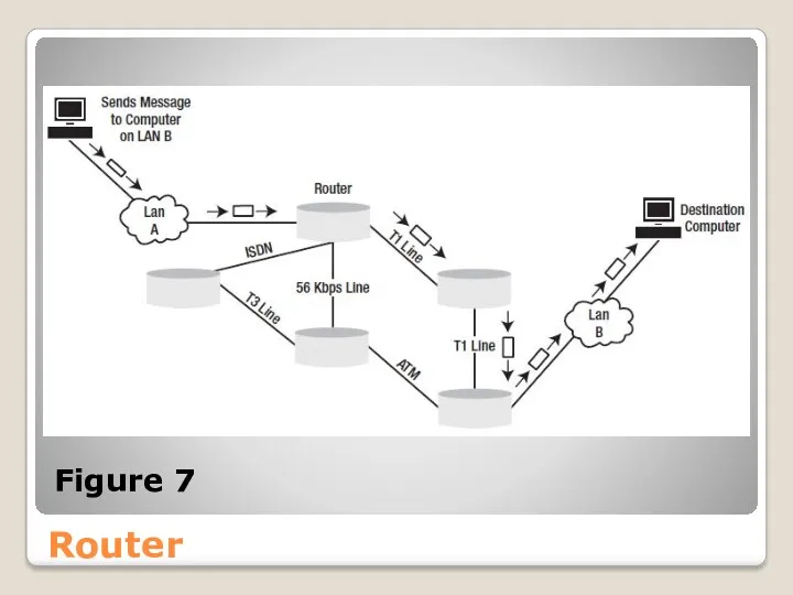
- 47. Router Routers are not only used within LANs, but also have an important place in WANs
- 48. Router Figure 7
- 49. Router A router holds a routing table that lists the ways particular networks can be reached.
- 50. Router The information that a router collates about the paths between networks is known as router
- 51. Router Distance vector routing protocols: Routing Information Protocol and Interior Gateway Routing Protocol use a hop
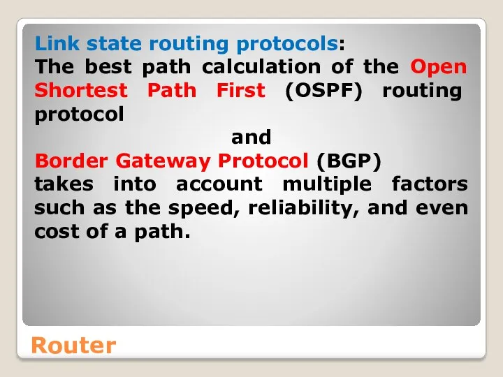
- 52. Router Link state routing protocols: The best path calculation of the Open Shortest Path First (OSPF)
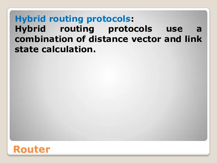
- 53. Router Hybrid routing protocols: Hybrid routing protocols use a combination of distance vector and link state
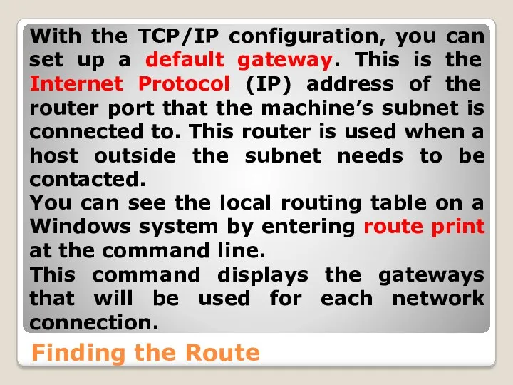
- 54. Finding the Route With the TCP/IP configuration, you can set up a default gateway. This is
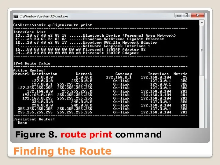
- 55. Finding the Route Figure 8. route print command
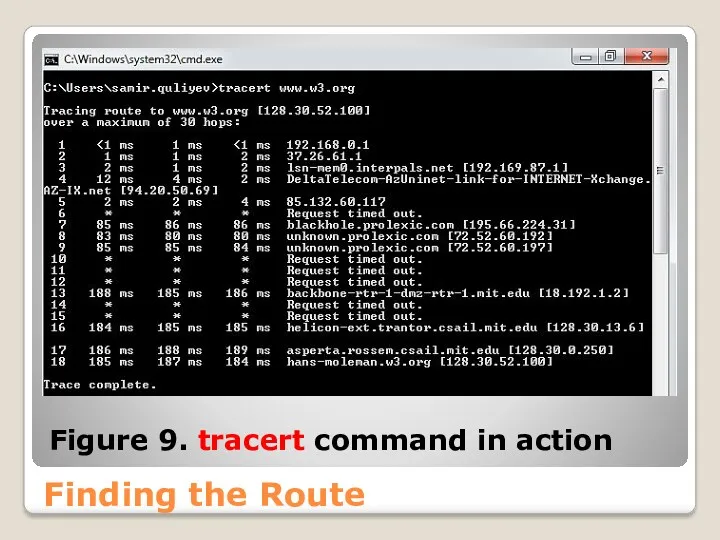
- 56. Finding the Route Another useful command is tracert. It allows you to examine the path used
- 57. Finding the Route Figure 9. tracert command in action
- 58. References Computer Networking: A Top-Down Approach (6th Edition) [James F. Kurose] [Keith W. Ross] 2012
- 59. References Computer Networks, Fifth Edition: A Systems Approach [Larry L. Peterson] [Bruce S. Davie] 2011
- 61. Скачать презентацию
Introduction
Network Programming is one of the central tasks when developing business
Introduction
Network Programming is one of the central tasks when developing business

Introduction
Why network programming in .NET Framework?
One of the first technical decisions
Introduction
Why network programming in .NET Framework?
One of the first technical decisions
Introduction
Why network programming in .NET Framework?
In fact, .NET Framework has more
Introduction
Why network programming in .NET Framework?
In fact, .NET Framework has more
Introduction
What can a network program do?
A network program is any application
Introduction
What can a network program do?
A network program is any application
Introduction
What can a network program do?
In case of a browser, every
Introduction
What can a network program do?
In case of a browser, every
Introduction
What can a network program do?
Our course is largely concerned with
Introduction
What can a network program do?
Our course is largely concerned with
Introduction
What can a network program do?
Users generally trust network applications, and
Introduction
What can a network program do?
Users generally trust network applications, and

Introduction
What can a network program do?
More importantly, from a networking perspective,
Introduction
What can a network program do?
More importantly, from a networking perspective,
Introduction
What can a network program do?
This applies even when the Web
Introduction
What can a network program do?
This applies even when the Web
Networking Concepts and Protocols
Let’s introduce some of the basic networking concepts
Networking Concepts and Protocols
Let’s introduce some of the basic networking concepts
Networking Concepts and Protocols
Then we take a look at the seven
Networking Concepts and Protocols
Then we take a look at the seven
Networking Concepts and Protocols
Outline
The physical network
The OSI seven-layer model
Network protocols (including
Networking Concepts and Protocols
Outline
The physical network
The OSI seven-layer model
Network protocols (including

The Physical Network
In essence, a network is a group of computers
The Physical Network
In essence, a network is a group of computers
The Physical Network
Nodes are connected by links, which could be cables
The Physical Network
Nodes are connected by links, which could be cables
The Physical Network
We can differentiate networks according to their size:
Local Area
The Physical Network
We can differentiate networks according to their size:
Local Area
The Physical Network
A Wide Area Network (WAN) connects multiple LAN sites.
The Physical Network
A Wide Area Network (WAN) connects multiple LAN sites.
The Physical Network
A Metropolitan Area Network (MAN) is very similar to
The Physical Network
A Metropolitan Area Network (MAN) is very similar to

The Physical Network
Backbone
In discussions about networks, the term “backbone” is often
The Physical Network
Backbone
In discussions about networks, the term “backbone” is often
Ethernet
Let’s look at the most common LAN network architecture – Ethernet.
Ethernet
Let’s look at the most common LAN network architecture – Ethernet.
Ethernet
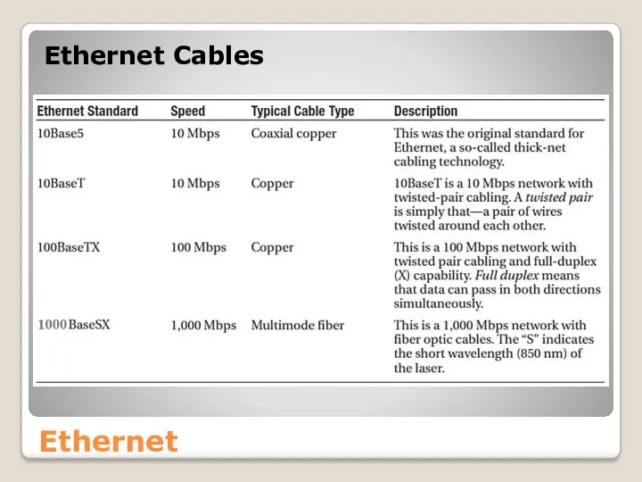
There is a standard naming convention that indicates the speed of
Ethernet
There is a standard naming convention that indicates the speed of
Ethernet
Ethernet Cables
Ethernet
Ethernet Cables
Ethernet (CSMA/CD)
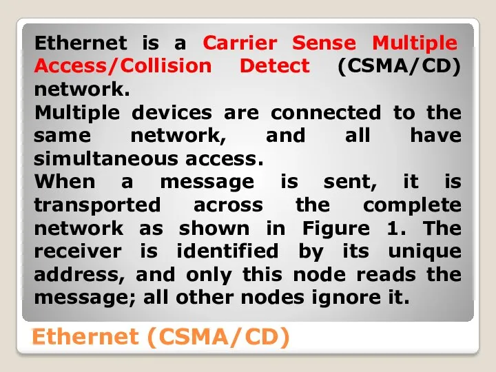
Ethernet is a Carrier Sense Multiple Access/Collision Detect (CSMA/CD) network.
Ethernet (CSMA/CD)
Ethernet is a Carrier Sense Multiple Access/Collision Detect (CSMA/CD) network.
Ethernet (CSMA/CD)
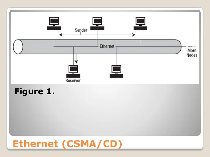
Figure 1.
Ethernet (CSMA/CD)
Figure 1.
Ethernet (CSMA/CD)
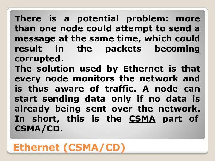
There is a potential problem: more than one node could
Ethernet (CSMA/CD)
There is a potential problem: more than one node could
Ethernet (CSMA/CD)
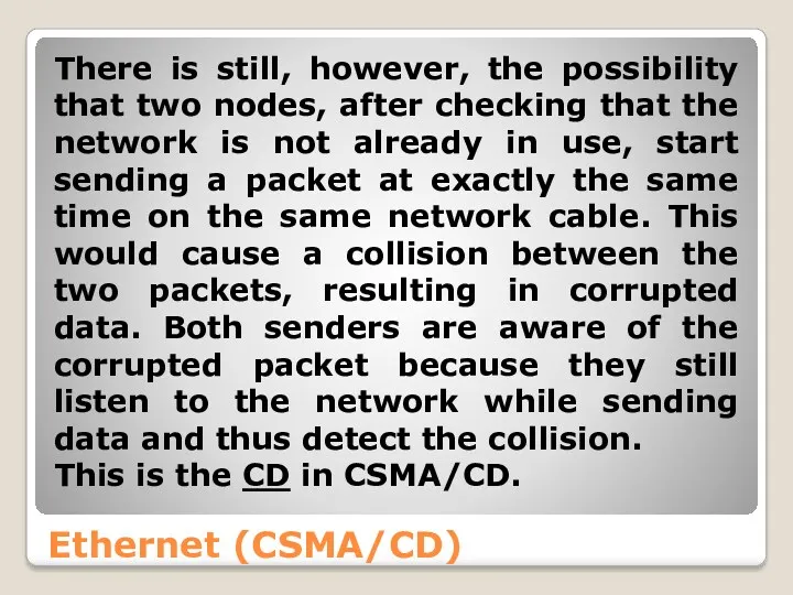
There is still, however, the possibility that two nodes, after
Ethernet (CSMA/CD)
There is still, however, the possibility that two nodes, after
Ethernet (CSMA/CD)
Both nodes then halt their transmissions immediately and wait a
Ethernet (CSMA/CD)
Both nodes then halt their transmissions immediately and wait a

Ethernet (CSMA/CD)
Every node on the local network uses a Media Access
Ethernet (CSMA/CD)
Every node on the local network uses a Media Access

Token Ring (IEEE 802.5) is a network architecture developed by IBM.
Token Ring (IEEE 802.5) is a network architecture developed by IBM.

Figure 2
Other Network Architectures
Figure 2
Other Network Architectures
Other Network Architectures
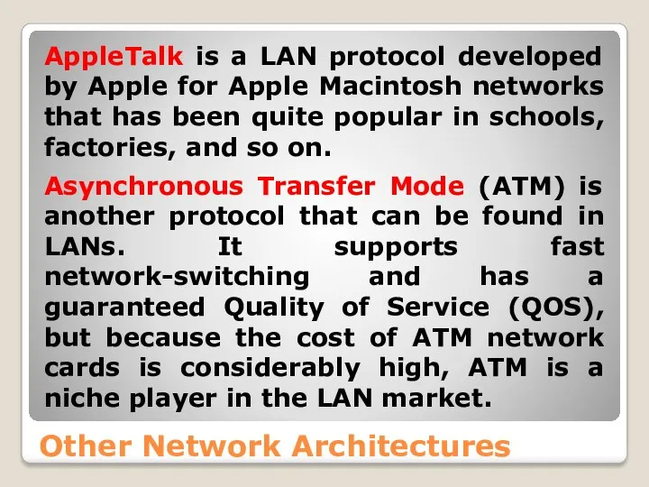
AppleTalk is a LAN protocol developed by Apple for
Other Network Architectures
AppleTalk is a LAN protocol developed by Apple for
Physical Components
An important aspect of understanding the network is knowing the
Physical Components
An important aspect of understanding the network is knowing the
Network Interface Card (NIC)
A NIC is the adapter card used to
Network Interface Card (NIC)
A NIC is the adapter card used to
Network Interface Card (NIC)
You can find the MAC address of a
Network Interface Card (NIC)
You can find the MAC address of a

Network Interface Card (NIC)
http://www.adminsub.net/mac-address-finder
Figure 3
Network Interface Card (NIC)
http://www.adminsub.net/mac-address-finder
Figure 3
Hub
Multiple devices can easily be connected with the help of a
Hub
Multiple devices can easily be connected with the help of a
Hub
Figure 4
Hub
Figure 4
Hub
The hub acts as a repeater as it forwards every message
Hub
The hub acts as a repeater as it forwards every message
Switch
Switches separate networks into segments. Compared to a hub, a switch
Switch
Switches separate networks into segments. Compared to a hub, a switch
Switch
As shown in Figure 5, a switch can be used to
Switch
As shown in Figure 5, a switch can be used to
Switch
Figure 5
Switch
Figure 5
Switch
This sort of arrangement was popular in the early days, when
Switch
This sort of arrangement was popular in the early days, when
Router
A router is an intermediary network device that connects multiple physical
Router
A router is an intermediary network device that connects multiple physical
Router
● The capability of restricting users to particular subnets offers security
Router
● The capability of restricting users to particular subnets offers security
Router
Figure 6
Router
Figure 6

Router
Note
If you’re using a router in a LAN, be aware that
Router
Note
If you’re using a router in a LAN, be aware that
Router
Routers are not only used within LANs, but also have an
Router
Routers are not only used within LANs, but also have an
Router
Figure 7
Router
Figure 7
Router
A router holds a routing table that lists the ways particular
Router
A router holds a routing table that lists the ways particular
Router
The information that a router collates about the paths between networks
Router
The information that a router collates about the paths between networks

Router
Distance vector routing protocols: Routing Information Protocol
and
Interior Gateway Routing Protocol
Router
Distance vector routing protocols: Routing Information Protocol
and
Interior Gateway Routing Protocol
Router
Link state routing protocols:
The best path calculation of the Open
Router
Link state routing protocols:
The best path calculation of the Open
Router
Hybrid routing protocols:
Hybrid routing protocols use a combination of distance
Router
Hybrid routing protocols:
Hybrid routing protocols use a combination of distance
Finding the Route
With the TCP/IP configuration, you can set up a
Finding the Route
With the TCP/IP configuration, you can set up a
Finding the Route
Figure 8. route print command
Finding the Route
Figure 8. route print command

Finding the Route
Another useful command is tracert. It allows you to
Finding the Route
Another useful command is tracert. It allows you to
Finding the Route
Figure 9. tracert command in action
Finding the Route
Figure 9. tracert command in action
![References Computer Networking: A Top-Down Approach (6th Edition) [James F. Kurose] [Keith W. Ross] 2012](/_ipx/f_webp&q_80&fit_contain&s_1440x1080/imagesDir/jpg/315184/slide-57.jpg)
References
Computer Networking: A Top-Down Approach (6th Edition)
[James F. Kurose]
[Keith W. Ross]
2012
References
Computer Networking: A Top-Down Approach (6th Edition)
[James F. Kurose]
[Keith W. Ross]
2012
![References Computer Networks, Fifth Edition: A Systems Approach [Larry L. Peterson] [Bruce S. Davie] 2011](/_ipx/f_webp&q_80&fit_contain&s_1440x1080/imagesDir/jpg/315184/slide-58.jpg)
References
Computer Networks, Fifth Edition: A Systems Approach
[Larry L. Peterson]
[Bruce S. Davie]
2011
References
Computer Networks, Fifth Edition: A Systems Approach
[Larry L. Peterson]
[Bruce S. Davie]
2011
 Главные тренды
 Подготовка эффективных презентаций
 Измерение информации
 Комплекс по оптимизации аппаратно-программного обеспечения
 презентация воскресенский
 Комп'ютерні мережі
 Архитектура ЭВМ
 Косметология. Шаблон
 Расчет геометрических параметров объекта
 Презентация по информатике 6 класс Компьютер - универсальная машина для работы с информацией
 Для чего нужны СМИ
 Apx UI. New UI. Marvell Confidential
 Информационнная безопасность РФ и проблемы ее обеспечения в условиях межгосударственного противоборства
 NTFS MFT Example
 Правила создания презентации в программе Power Point для школьников
 Лекция 2 – Основы языка C#
 Основы работы в системе MAPLE
 Процессы и потоки. Лекция 3
 Дизайн сайта
 Сети ISDN. Технология xDSL
 Инвестиции
 Операциялық жүйелер. Операциялық жүйелердің даму тарихы
 Интернет-сервис Антиплагиат. Ру
 Притяжение. Действие магнита
 Основы программирования. Лабораторная работа №5. Рекурсия
 Практическое применение 3D-моделирования
 Модели CatBoost в ClickHouse
 Программа MS Access