- System Principal

Содержание
- 2. System structure example 1 Boom system (eg. Boltec) Upper CAN D510 I/ O Common. D501 OP
- 3. System structure example 2 Boom system (eg L2C) Upper CAN D510 I/ O Common. D501 OP
- 4. Lower CAN Lower CAN System structure example 2 Boom system, ex Boomer L2 C With options
- 5. System structure principal ROC F9C Upper CAN D100 APP Boom Lower CAN Boom Boom 102 I
- 6. Lower CAN Lower CAN System structure principal Upper CAN line = Can Cable Termination in both
- 7. Plugs Endplugs and adressplugs 9106 0968 00 0-9106 1324 30 1-9106 1324 31 2-9106 1324 32
- 8. Lower CAN Lower CAN I / O I / O System structure Plugs Upper CAN I
- 9. Boom CAN Adress example Feed forward on boom 2 D510 I/ O Common. D501 OP D100
- 10. Connections on modules Connections X1 Power supply X2 CAN in/out (Lower CAN Communication) X3 CAN in/out
- 11. Connections on modules I/O Module Diode 1 time/ sec = OK 2 time/Sec = No connection
- 12. Connections on modules Resolver module
- 13. Connections on modules Operating panel/Display
- 14. Connections on modules Decoder modules in the operating panel
- 15. System structure principal Upper CAN Lower Can =
- 16. System structure With all adresses and end plugs
- 17. CAN Power supply Principal of fuses to the modules
- 18. Drawing example Boomer L2C
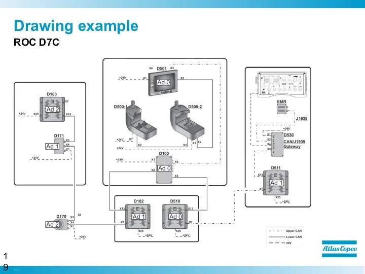
- 19. Drawing example ROC D7C
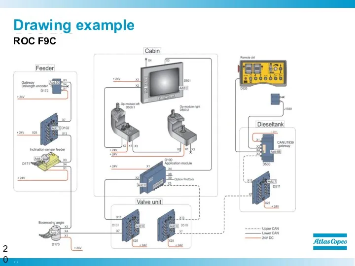
- 20. Drawing example ROC F9C
- 21. CAN on rig Boomer L2C
- 22. We are committed to your superior productivity through interaction and innovation.
- 24. Скачать презентацию
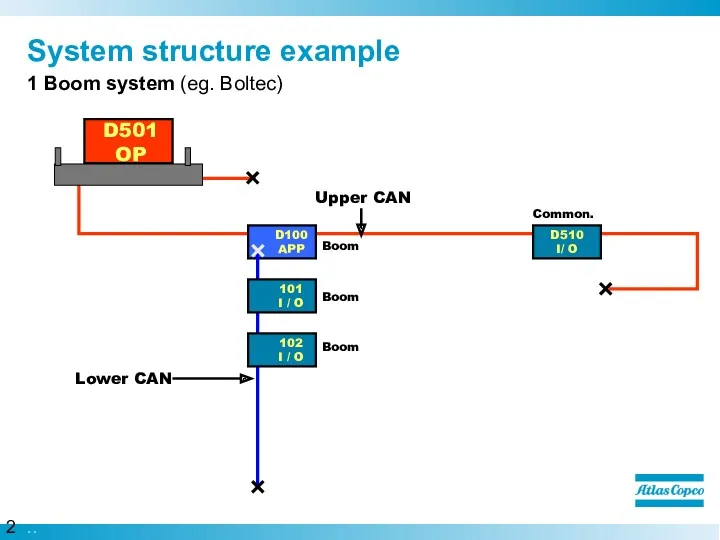
System structure example
1 Boom system (eg. Boltec)
Upper CAN
D510
I/ O
Common.
D501
OP
D100
APP
Boom
Boom
101
I /
System structure example
1 Boom system (eg. Boltec)
Upper CAN
D510
I/ O
Common.
D501
OP
D100
APP
Boom
Boom
101
I /
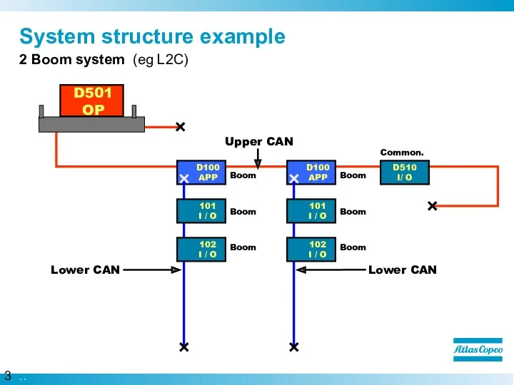
System structure example
2 Boom system (eg L2C)
Upper CAN
D510
I/ O
Common.
D501
OP
D100
APP
Boom
Boom
101
I / O
Boom
102
I
System structure example
2 Boom system (eg L2C)
Upper CAN
D510
I/ O
Common.
D501
OP
D100
APP
Boom
Boom
101
I / O
Boom
102
I
Lower CAN
Lower CAN
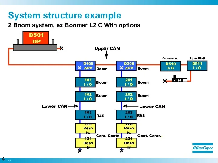
System structure example
2 Boom system, ex Boomer L2 C
Lower CAN
Lower CAN
System structure example
2 Boom system, ex Boomer L2 C
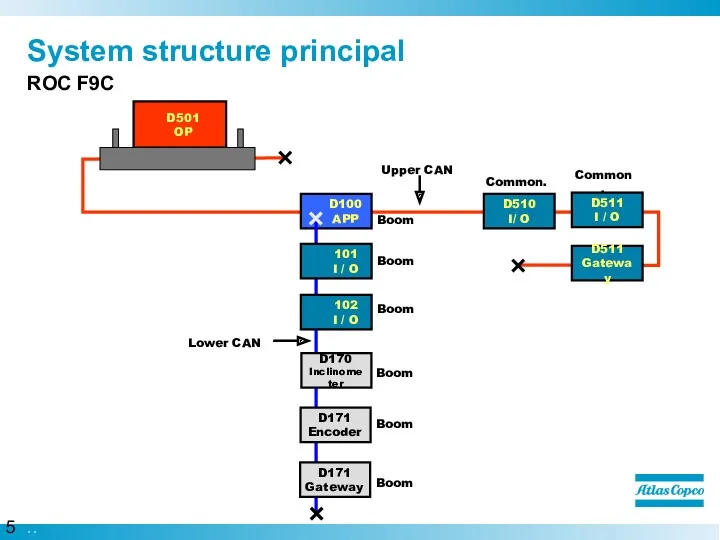
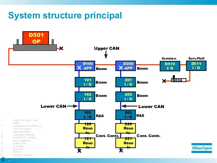
System structure principal
ROC F9C
Upper CAN
D100
APP
Boom
Lower CAN
Boom
Boom
102
I / O
101
I / O
D511
I /
System structure principal
ROC F9C
Upper CAN
D100
APP
Boom
Lower CAN
Boom
Boom
102
I / O
101
I / O
D511
I /
Lower CAN
Lower CAN
System structure principal
Upper CAN line = Can Cable
Termination in
Lower CAN
Lower CAN
System structure principal
Upper CAN line = Can Cable
Termination in
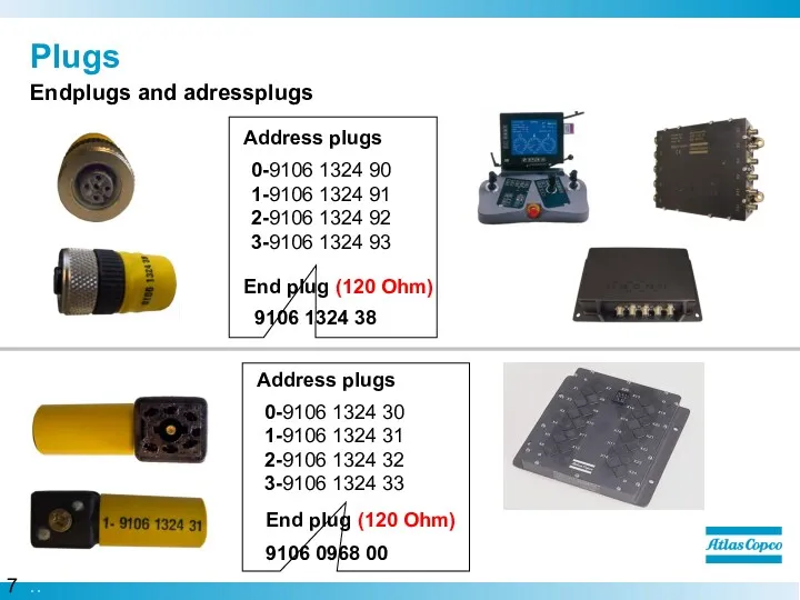
Plugs
Endplugs and adressplugs
9106 0968 00
0-9106 1324 30
1-9106 1324 31
2-9106 1324 32
3-9106
Plugs
Endplugs and adressplugs
9106 0968 00
0-9106 1324 30
1-9106 1324 31
2-9106 1324 32
3-9106
Lower CAN
Lower CAN
I / O
I / O
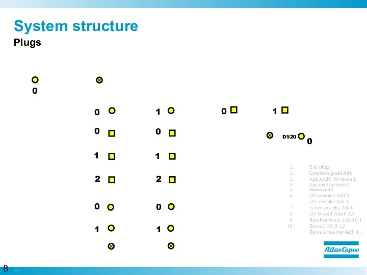
System structure
Plugs
Upper CAN
I / O
I/
Lower CAN
Lower CAN
I / O
I / O
System structure
Plugs
Upper CAN
I / O
I/

Boom
CAN Adress example
Feed forward on boom 2
D510
I/ O
Common.
D501
OP
D100
APP
Boom
Boom
101
I / O
Boom
102
I /
Boom
CAN Adress example
Feed forward on boom 2
D510
I/ O
Common.
D501
OP
D100
APP
Boom
Boom
101
I / O
Boom
102
I /
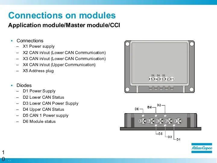
Connections on modules
Connections
X1 Power supply
X2 CAN in/out (Lower CAN Communication)
X3 CAN
Connections on modules
Connections
X1 Power supply
X2 CAN in/out (Lower CAN Communication)
X3 CAN
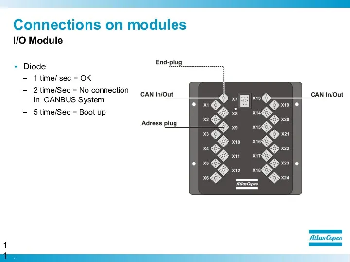
Connections on modules
I/O Module
Diode
1 time/ sec = OK
2 time/Sec = No
Connections on modules
I/O Module
Diode
1 time/ sec = OK
2 time/Sec = No
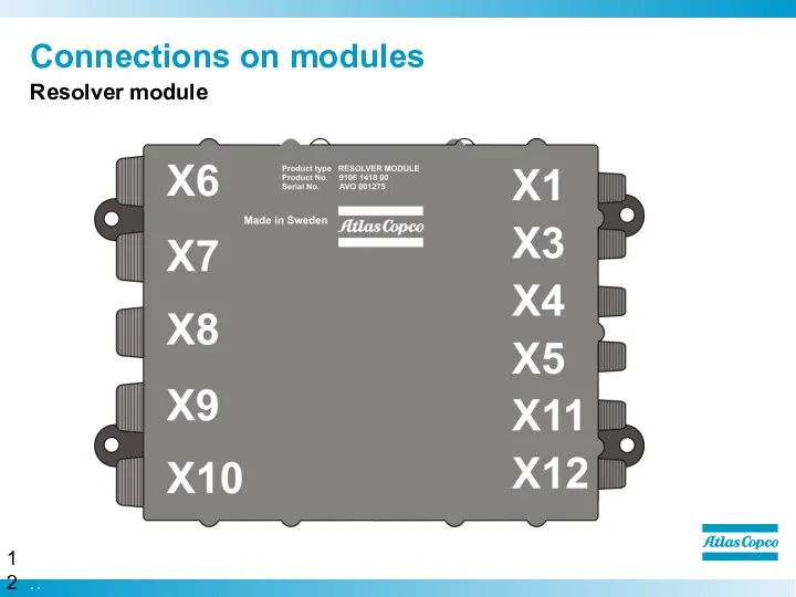
Connections on modules
Resolver module
Connections on modules
Resolver module
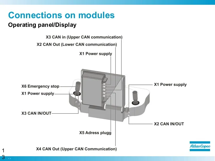
Connections on modules
Operating panel/Display
Connections on modules
Operating panel/Display
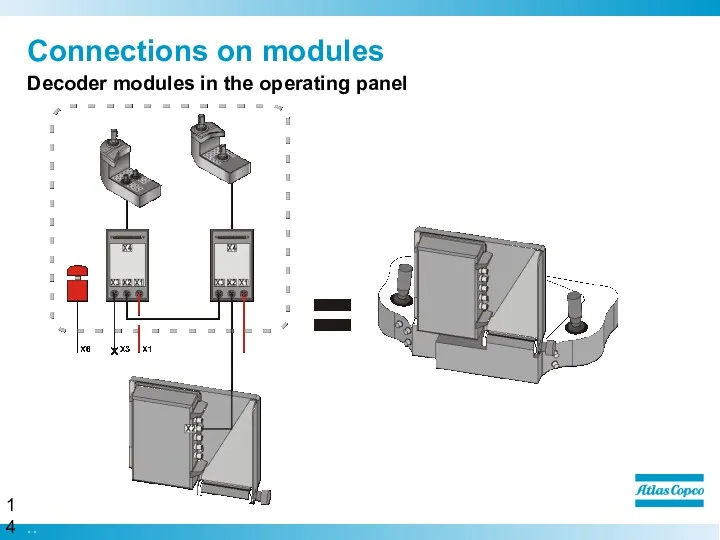
Connections on modules
Decoder modules in the operating panel
Connections on modules
Decoder modules in the operating panel
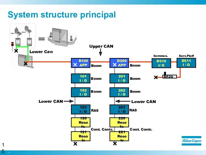
System structure principal
Upper CAN
Lower Can
=
System structure principal
Upper CAN
Lower Can
=
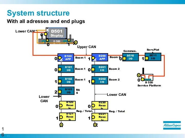
System structure
With all adresses and end plugs
System structure
With all adresses and end plugs
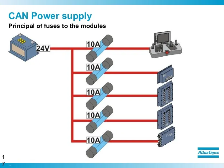
CAN Power supply
Principal of fuses to the modules
CAN Power supply
Principal of fuses to the modules
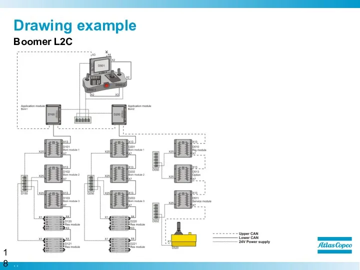
Drawing example
Boomer L2C
Drawing example
Boomer L2C
Drawing example
ROC D7C
Drawing example
ROC D7C
Drawing example
ROC F9C
Drawing example
ROC F9C
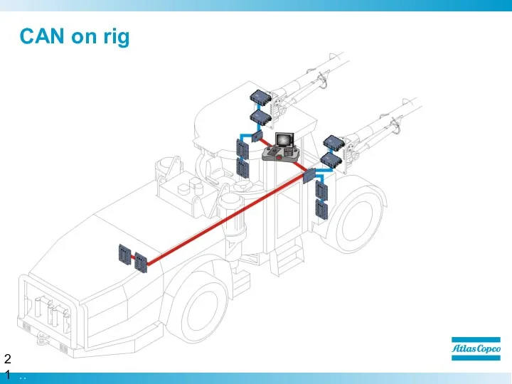
CAN on rig
Boomer L2C
CAN on rig
Boomer L2C

We are committed to your superior productivity through
interaction and innovation.
We are committed to your superior productivity through
interaction and innovation.
 Автоматизоване створення запитів у базі даних
 Компьютерные презентации. Разработка и создание презентации
 Алгоритмы и способы их описания
 Обучающая игра Нажми на мышку
 Операции, операторы, операнды
 Работа с сайтом Госуслуги
 Вычислительные системы. Локальные сети
 Инструкция по обновлению BIOS для win7
 Мова програмування python
 Что нам стоит клип построить
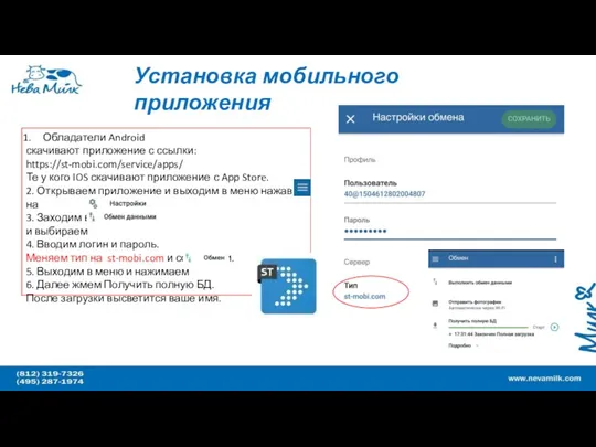 Установка мобильного приложения Mobi.com компании Нева Милк
 Организационно-административное обеспечение информационной безопасности
 Создание Telegram-бота
 Газеты и журналы в библиотеке. МБУК Вышневолоцкая ЦБ Терелесовская библиотека
 Разработка игры-платформера на движке Unity
 Информационно-образовательная среда
 Особливості мови програмування Java (лекція 1)
 Программное обеспечение. §38. Что такое программное
 Электронна комерція в Україні
 Функціональні залежності
 Расчетные методики ПП ЭкоСфера-предприятие. Расчет выбросов от автотранспорта (внутренний проезд)
 Алгоритм - модель деятельности исполнения алгоритмов
 Вирусы и антивирусы
 Моделирование как метод научного исследования
 Графические и табличные информационные модели
 Права и обязанности в интернет-пространстве
 Інформатика. Інформація. Види інформації. Властивості інформації. Інформаційні процеси. Кодування інформації
 Bubble Sort