- “VRFs” and “Multiprotocol BGP”

Содержание
- 2. The Topology The next two slides display both the physical and logical topology of our simple
- 5. Laying The Foundations Terms that are often heard in close proximity to “MPLS VPN” are “VRFs”
- 6. Inside The Cloud
- 7. Overlaying MPLS VPNs Now that the ‘cloud’ has basic MPLS IP Unicast Forwarding enabled we can
- 8. Customer to Provider As MPLS is a layer 3 technology a method of communicating routing information
- 9. Advertisement Flow
- 10. Traffic Flow
- 11. MPLS VPN - CE to PE Static Routing Example
- 12. MPLS VPN - CE to PE RIPv2 Example
- 13. MPLS VPN - CE to PE EIGRP Example
- 14. MPLS VPN - CE to PE OSPF Example
- 16. Скачать презентацию
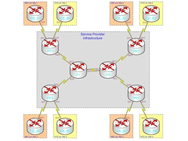
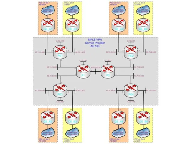
The Topology
The next two slides display both the physical and logical
The Topology
The next two slides display both the physical and logical
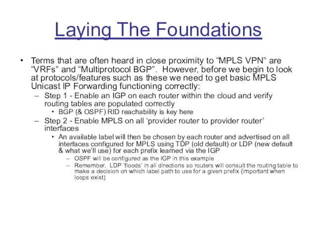
Laying The Foundations
Terms that are often heard in close proximity to
Laying The Foundations
Terms that are often heard in close proximity to
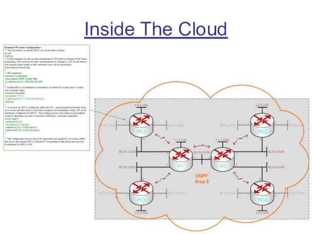
Inside The Cloud
Inside The Cloud
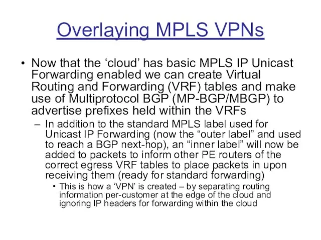
Overlaying MPLS VPNs
Now that the ‘cloud’ has basic MPLS IP Unicast
Overlaying MPLS VPNs
Now that the ‘cloud’ has basic MPLS IP Unicast
Customer to Provider
As MPLS is a layer 3 technology a method
Customer to Provider
As MPLS is a layer 3 technology a method
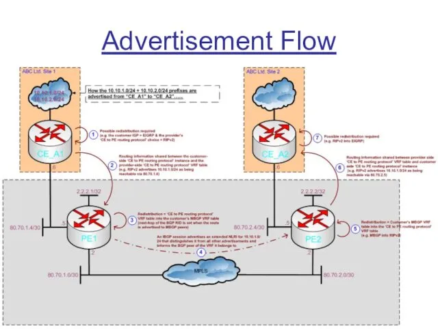
Advertisement Flow
Advertisement Flow
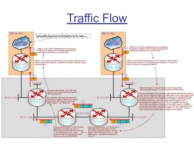
Traffic Flow
Traffic Flow
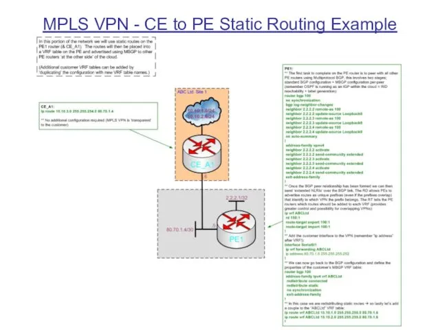
MPLS VPN - CE to PE Static Routing Example
MPLS VPN - CE to PE Static Routing Example
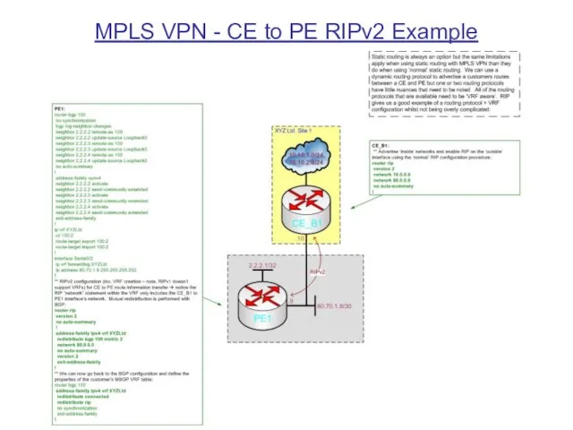
MPLS VPN - CE to PE RIPv2 Example
MPLS VPN - CE to PE RIPv2 Example
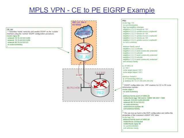
MPLS VPN - CE to PE EIGRP Example
MPLS VPN - CE to PE EIGRP Example
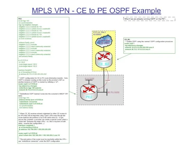
MPLS VPN - CE to PE OSPF Example
MPLS VPN - CE to PE OSPF Example
 Локальные и глобальные компьютерные сети. Коммуникационные технологии
 Алгоритмы и исполнители. Основы алгоритмизации
 Табличные информационные модели. Моделирование и формализация (9 класс)
 Цензура в США: СМИ и Интернет
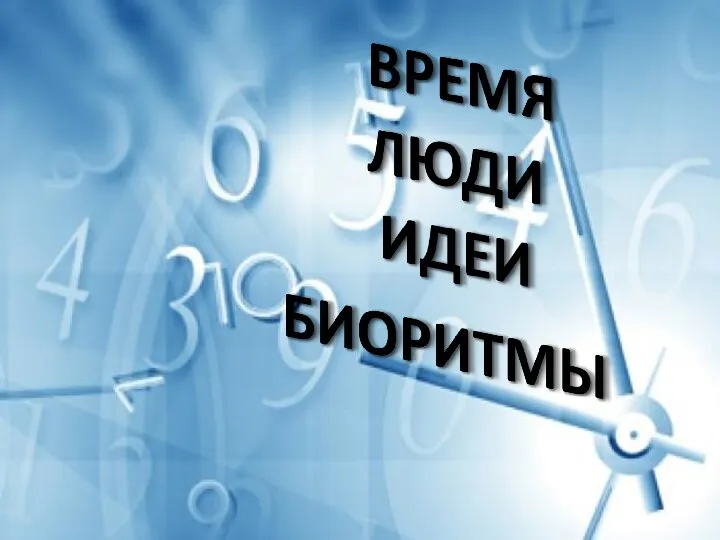 Урок в рамках модуля Время. Люди. События
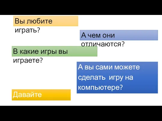 Конструктор игр
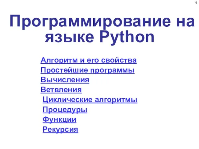 Программирование на языке Python
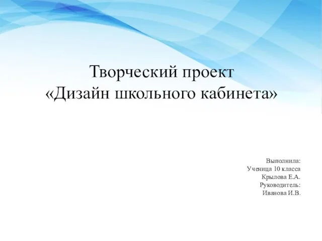 Творческий проект Дизайн школьного кабинета
 Разработка корпоративного веб-сайта
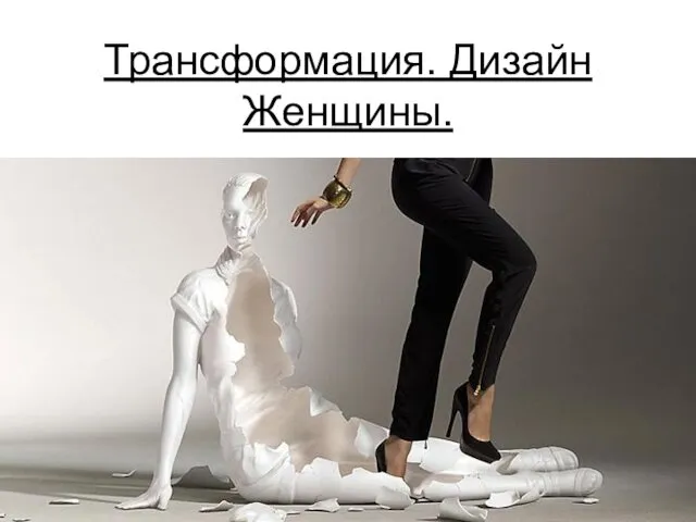 Вебинар. Трансформация. Дизайн женщины
 Основы безопасности информационных технологий. Средства защиты от нарушений
 Сообщество adidas runners и RunClubKirov в Strava
 Технология подготовки текстовых документов
 Secrets Which you never noticed in Night Shift at Freddy’s
 Логическая организация баз данных. Лекция 2
 Визуализация информации в текстовых документах
 Моделирование на UML. Первая ступень Тест
 Компьютер в жизни ребенка
 Каналы передачи информации
 Растровая модель пространственных данных. Лекция 2
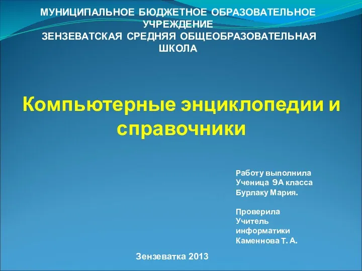 Электронные энциклопедии и справочники
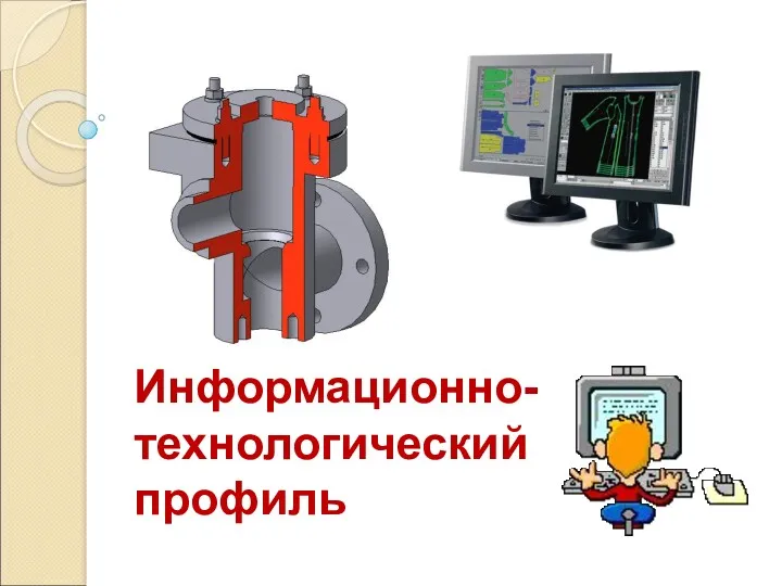 Информационно-технологический профиль
 Информационно-коммуникационные технологии в учебном процессе
 Основні режими Microsoft PowerPoint
 Тестирование ПО. Методики тестирования. Лекция 5
 Графикалық режім
 Роботы
 Операционная система Linux