- What’s the Internet

Содержание
- 2. Part I: Introduction Our goal: Get context, overview, “feel” of networking More depth, detail later in
- 3. Outline What is the Internet? Network Edge Network Core Delay, Loss, Throughput in Networks Protocol Layers,
- 4. What’s the Internet: “Nuts and bolts” view Millions of connected computing devices: Hosts = end systems
- 5. “Cool” Internet Appliances IP picture frame http://www.ceiva.com/ Web-enabled toaster + weather forecaster Internet phones Internet refrigerator
- 6. What’s the Internet: “Nuts and Bolts” View Internet: “network of networks” Loosely hierarchical Public Internet versus
- 7. What’s the Internet: A Service View Infrastructure that provides services to applications: Web, VoIP, email, games,
- 8. What’s a Protocol? (1) Human Protocols: “What’s the time?” “I have a question” Introductions … specific
- 9. What’s a Protocol? (2) Human protocol and computer network protocol: Q: Other human protocols? Hi Hi
- 10. Outline What is the Internet? Network Edge Network Core Delay, Loss, Throughput in Networks Protocol Layers,
- 11. Closer Look at Network Structure Network edge: Applications and hosts Access networks, physical media: Wired, wireless
- 12. The Network Edge End systems (hosts): Run application programs e.g., WWW, email at “edge of network”
- 13. Network Edge: Connection-Oriented Service Goal: Data transfer between end systems Handshaking: setup (prepare for) data transfer
- 14. Network Edge: Connectionless Service Goal: Data transfer between end systems Same as before! UDP - User
- 15. Access Networks and Physical Media Q: How to connect end systems to edge router? Residential access
- 16. Outline What is the Internet? Network Edge Network Core Delay, Loss, Throughput in Networks Protocol Layers,
- 17. The Network Core Mesh of interconnected routers The fundamental question: how is data transferred through network?
- 18. Network Core: Circuit Switching (1) End-end resources reserved for “call”: Link bandwidth, switch capacity Dedicated resources:
- 19. Network Core: Circuit Switching (2) Network resources (e.g., bandwidth) divided into “pieces” Pieces allocated to calls
- 20. Circuit Switching: FDM and TDM
- 21. Network Core: Packet Switching (1) Each end-end data stream divided into packets Users A, B packets
- 22. Network Core: Packet Switching (2) A B C 10 Mbs Ethernet 1.5 Mbps 45 Mbps Statistical
- 23. Packet Switching Versus Circuit Switching 1 Mbit link Each user: 100 Kbps when “active” Active 10%
- 24. Packet-Switched Networks: Routing Goal: Move packets among routers from source to destination We’ll study several path
- 25. Internet Structure: Network of Networks Roughly hierarchical National/international backbone providers (NBPs) e.g. BBN/GTE, Sprint, AT&T, IBM,
- 26. National Backbone Provider e.g. Sprint US backbone network Example: Sprint
- 27. Outline What is the Internet? Network Edge Network Core Delay, Loss, Throughput in Networks Protocol Layers,
- 28. Delay in Packet-Switched Networks (1) Packets experience delay on end-to-end path Four sources of delay at
- 29. Delay in Packet-Switched Networks (2) Transmission Delay: R = Link bandwidth (bps) L = Packet length
- 30. Queueing delay (revisited) R = Link bandwidth (bps) L = Packet length (bits) a = Average
- 31. “Real” Internet Delays and Routes 1 cs-gw (128.119.240.254) 1 ms 1 ms 2 ms 2 border1-rt-fa5-1-0.gw.umass.edu
- 32. Outline What is the Internet? Network Edge Network Core Delay, Loss, Throughput in Networks Protocol Layers,
- 33. Protocol “Layers” Networks are Complex! Many “pieces”: Hosts Routers Links of various media Applications Protocols Hardware,
- 34. Internet Protocol Stack Application: supporting network applications FTP, SMTP, HTTP Transport: host-host data transfer TCP, UDP
- 35. Layering: Logical Communication (1) Each layer: Distributed “Entities” implement layer functions at each node Entities perform
- 36. Layering: Logical Communication (2) E.g.: Transport layer Take data from app Add addressing, reliability check info
- 37. Layering: Physical Communication
- 38. Protocol Layering and Data Each layer takes data from above Adds header information to create new
- 39. Outline What is the Internet? Network Edge Network Core Delay, Loss, Throughput in Networks Protocol Layers,
- 40. Internet History (1) 1961: Kleinrock – queueing theory shows effectiveness of packet-switching 1964: Baran – packet-switching
- 41. Internet History (2) 1970: ALOHAnet satellite network in Hawaii 1973: Metcalfe’s PhD thesis proposes Ethernet 1974:
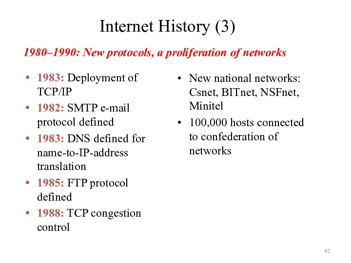
- 42. Internet History (3) 1983: Deployment of TCP/IP 1982: SMTP e-mail protocol defined 1983: DNS defined for
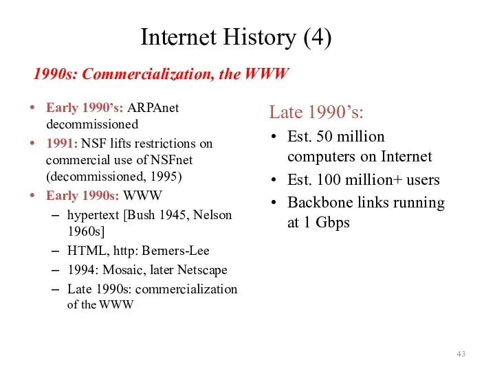
- 43. Internet History (4) Early 1990’s: ARPAnet decommissioned 1991: NSF lifts restrictions on commercial use of NSFnet
- 45. Скачать презентацию
Part I: Introduction
Our goal:
Get context, overview, “feel” of networking
More depth,
Part I: Introduction
Our goal:
Get context, overview, “feel” of networking
More depth,
Outline
What is the Internet?
Network Edge
Network Core
Delay, Loss, Throughput in Networks
Protocol Layers,
Outline
What is the Internet?
Network Edge
Network Core
Delay, Loss, Throughput in Networks
Protocol Layers,
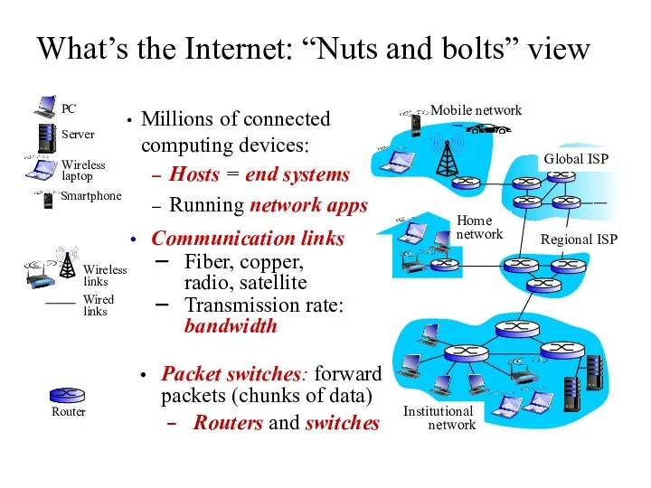
What’s the Internet: “Nuts and bolts” view
Millions of connected computing devices:
What’s the Internet: “Nuts and bolts” view
Millions of connected computing devices:
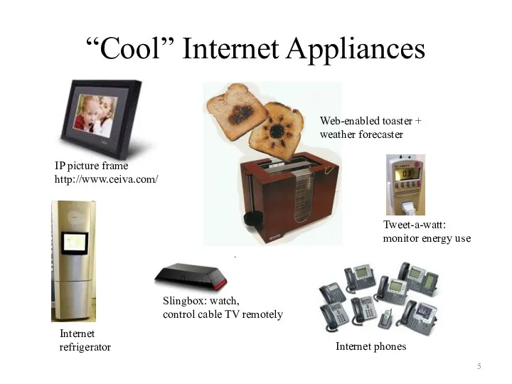
“Cool” Internet Appliances
IP picture frame
http://www.ceiva.com/
Web-enabled toaster +
weather forecaster
Internet phones
Internet
refrigerator
Slingbox: watch,
control
“Cool” Internet Appliances
IP picture frame
http://www.ceiva.com/
Web-enabled toaster +
weather forecaster
Internet phones
Internet
refrigerator
Slingbox: watch,
control
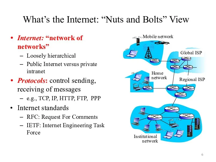
What’s the Internet: “Nuts and Bolts” View
Internet: “network of networks”
Loosely hierarchical
Public
What’s the Internet: “Nuts and Bolts” View
Internet: “network of networks”
Loosely hierarchical
Public
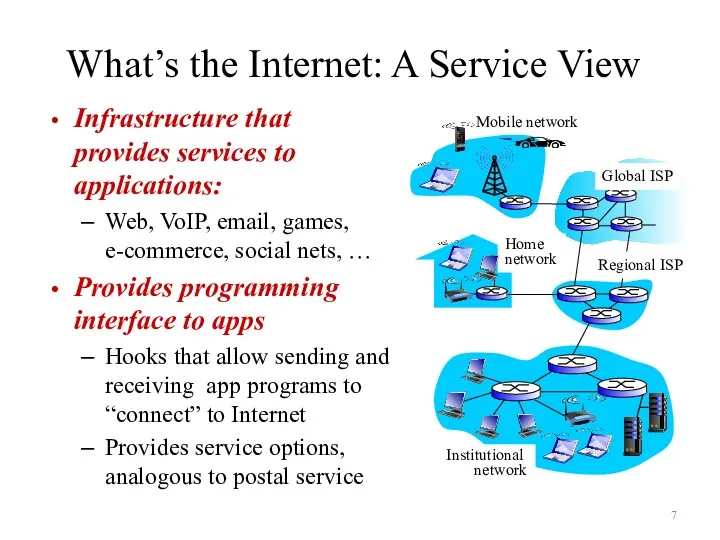
What’s the Internet: A Service View
Infrastructure that provides services to applications:
Web,
What’s the Internet: A Service View
Infrastructure that provides services to applications:
Web,
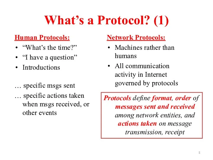
What’s a Protocol? (1)
Human Protocols:
“What’s the time?”
“I have a question”
Introductions
… specific
What’s a Protocol? (1)
Human Protocols:
“What’s the time?”
“I have a question”
Introductions
… specific
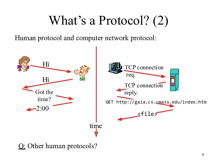
What’s a Protocol? (2)
Human protocol and computer network protocol:
Q: Other human
What’s a Protocol? (2)
Human protocol and computer network protocol:
Q: Other human
Outline
What is the Internet?
Network Edge
Network Core
Delay, Loss, Throughput in Networks
Protocol Layers,
Outline
What is the Internet?
Network Edge
Network Core
Delay, Loss, Throughput in Networks
Protocol Layers,
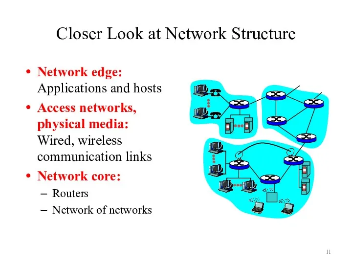
Closer Look at Network Structure
Network edge: Applications and hosts
Access networks, physical
Closer Look at Network Structure
Network edge: Applications and hosts
Access networks, physical
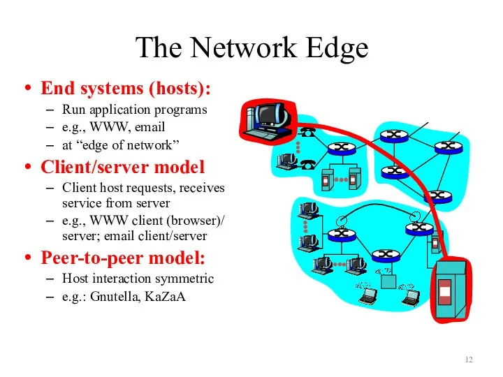
The Network Edge
End systems (hosts):
Run application programs
e.g., WWW, email
at “edge of
The Network Edge
End systems (hosts):
Run application programs
e.g., WWW, email
at “edge of
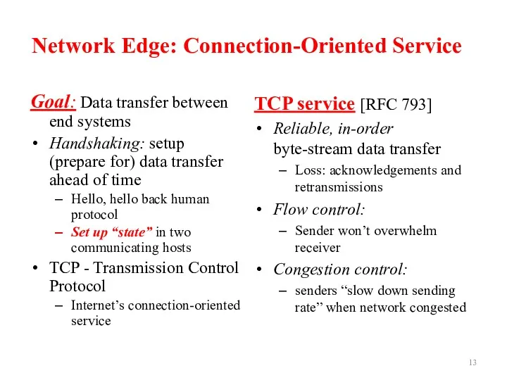
Network Edge: Connection-Oriented Service
Goal: Data transfer between end systems
Handshaking: setup (prepare
Network Edge: Connection-Oriented Service
Goal: Data transfer between end systems
Handshaking: setup (prepare
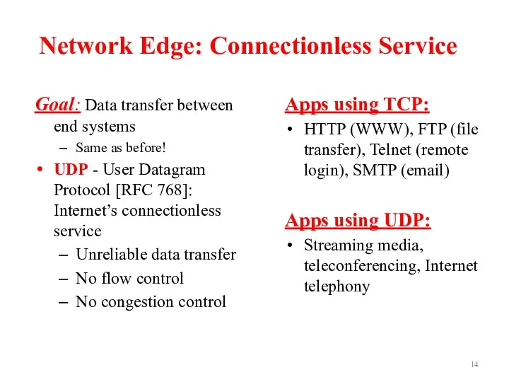
Network Edge: Connectionless Service
Goal: Data transfer between end systems
Same as before!
UDP
Network Edge: Connectionless Service
Goal: Data transfer between end systems
Same as before!
UDP
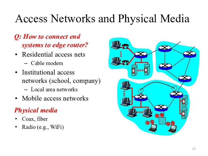
Access Networks and Physical Media
Q: How to connect end systems to
Access Networks and Physical Media
Q: How to connect end systems to
Outline
What is the Internet?
Network Edge
Network Core
Delay, Loss, Throughput in Networks
Protocol Layers,
Outline
What is the Internet?
Network Edge
Network Core
Delay, Loss, Throughput in Networks
Protocol Layers,
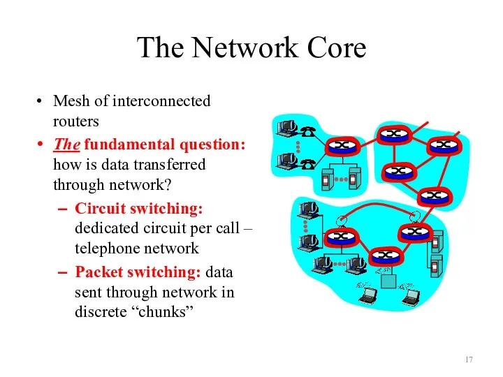
The Network Core
Mesh of interconnected routers
The fundamental question: how is data
The Network Core
Mesh of interconnected routers
The fundamental question: how is data
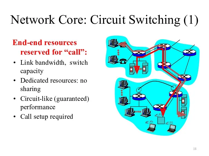
Network Core: Circuit Switching (1)
End-end resources reserved for “call”:
Link bandwidth, switch
Network Core: Circuit Switching (1)
End-end resources reserved for “call”:
Link bandwidth, switch
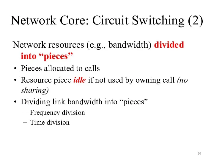
Network Core: Circuit Switching (2)
Network resources (e.g., bandwidth) divided into “pieces”
Pieces
Network Core: Circuit Switching (2)
Network resources (e.g., bandwidth) divided into “pieces”
Pieces
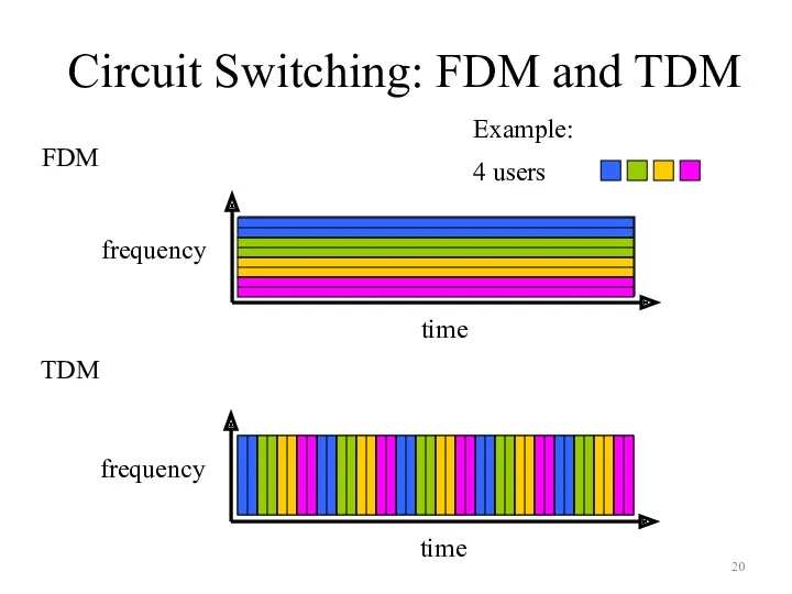
Circuit Switching: FDM and TDM
Circuit Switching: FDM and TDM
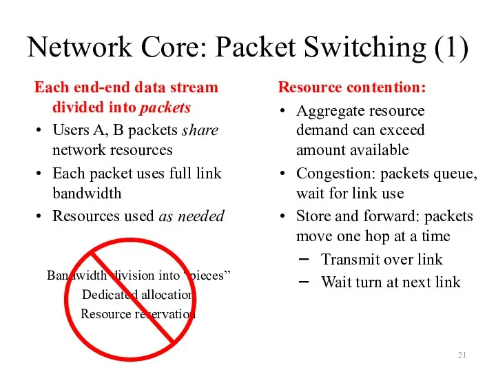
Network Core: Packet Switching (1)
Each end-end data stream divided into packets
Users
Network Core: Packet Switching (1)
Each end-end data stream divided into packets
Users
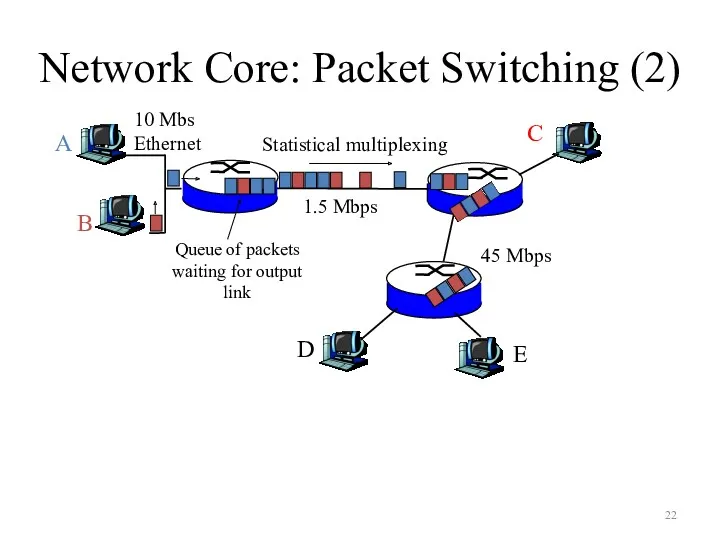
Network Core: Packet Switching (2)
A
B
C
10 Mbs
Ethernet
1.5 Mbps
45 Mbps
Statistical multiplexing
Queue of packets
waiting
Network Core: Packet Switching (2)
A
B
C
10 Mbs
Ethernet
1.5 Mbps
45 Mbps
Statistical multiplexing
Queue of packets
waiting
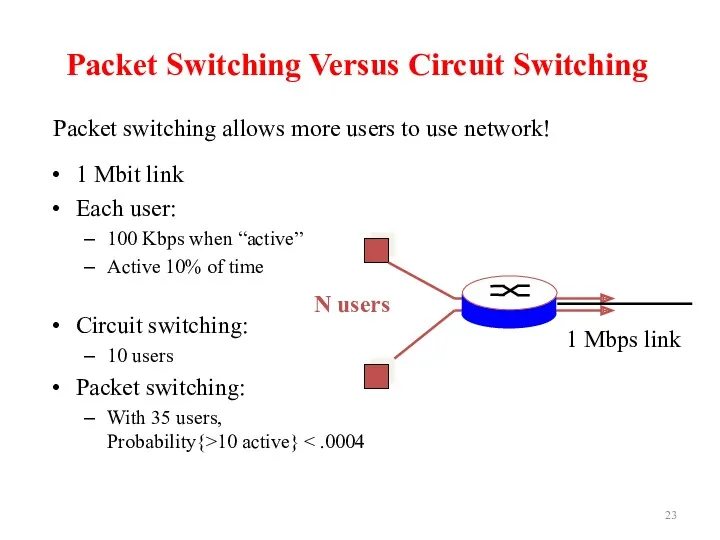
Packet Switching Versus Circuit Switching
1 Mbit link
Each user:
100 Kbps when
Packet Switching Versus Circuit Switching
1 Mbit link
Each user:
100 Kbps when
Packet-Switched Networks: Routing
Goal: Move packets among routers from source to destination
We’ll
Packet-Switched Networks: Routing
Goal: Move packets among routers from source to destination
We’ll
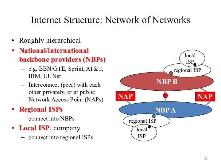
Internet Structure: Network of Networks
Roughly hierarchical
National/international backbone providers (NBPs)
e.g. BBN/GTE, Sprint,
Internet Structure: Network of Networks
Roughly hierarchical
National/international backbone providers (NBPs)
e.g. BBN/GTE, Sprint,
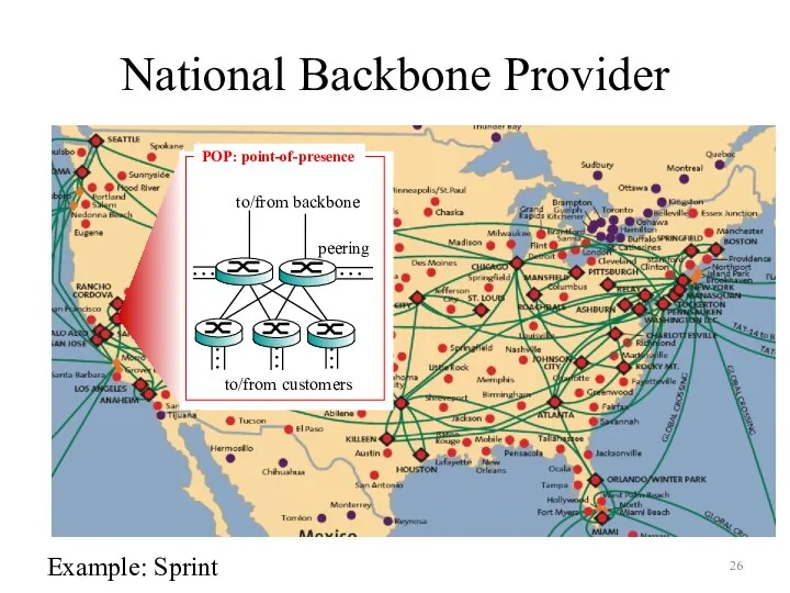
National Backbone Provider
e.g. Sprint US backbone network
Example: Sprint
National Backbone Provider
e.g. Sprint US backbone network
Example: Sprint
Outline
What is the Internet?
Network Edge
Network Core
Delay, Loss, Throughput in Networks
Protocol Layers,
Outline
What is the Internet?
Network Edge
Network Core
Delay, Loss, Throughput in Networks
Protocol Layers,
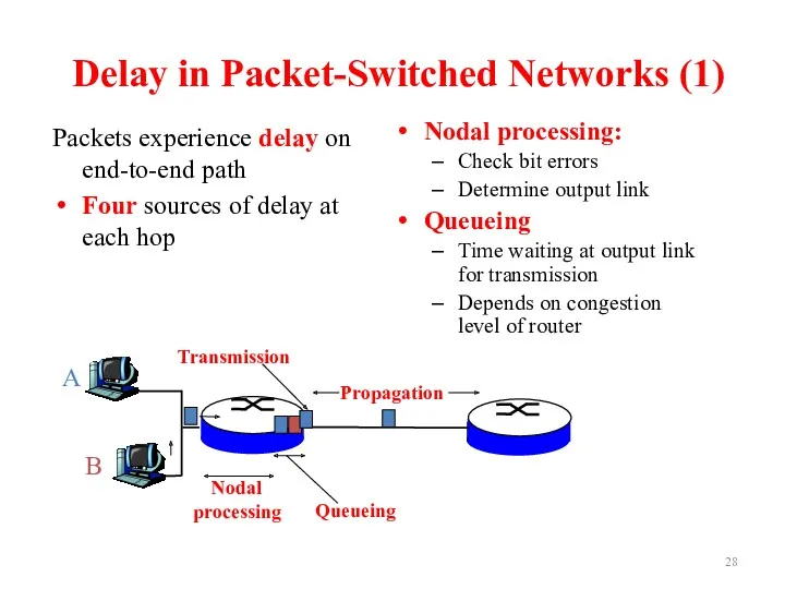
Delay in Packet-Switched Networks (1)
Packets experience delay on end-to-end path
Four sources
Delay in Packet-Switched Networks (1)
Packets experience delay on end-to-end path
Four sources
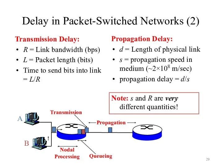
Delay in Packet-Switched Networks (2)
Transmission Delay:
R = Link bandwidth (bps)
L =
Delay in Packet-Switched Networks (2)
Transmission Delay:
R = Link bandwidth (bps)
L =
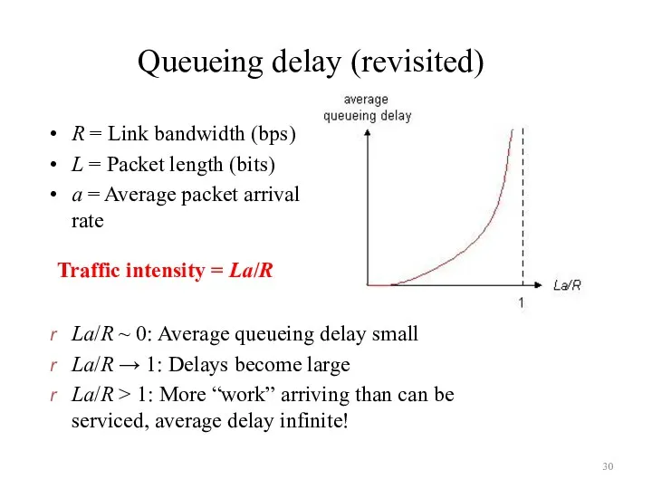
Queueing delay (revisited)
R = Link bandwidth (bps)
L = Packet length (bits)
a
Queueing delay (revisited)
R = Link bandwidth (bps)
L = Packet length (bits)
a
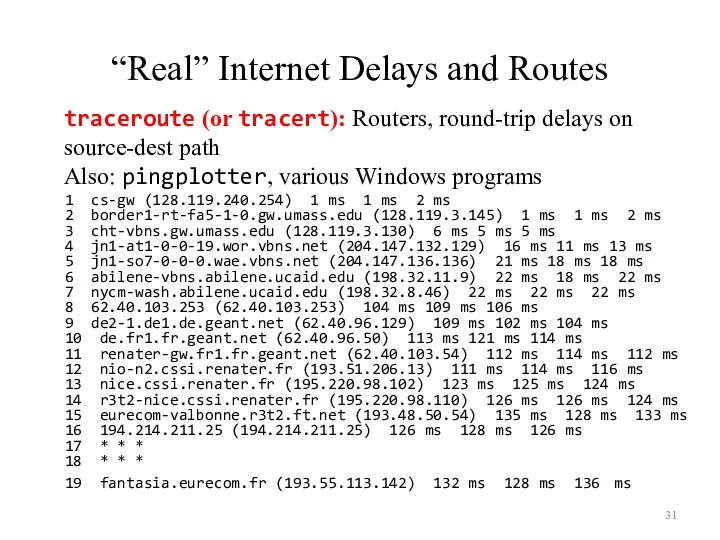
“Real” Internet Delays and Routes
1 cs-gw (128.119.240.254) 1 ms 1 ms
“Real” Internet Delays and Routes
1 cs-gw (128.119.240.254) 1 ms 1 ms
Outline
What is the Internet?
Network Edge
Network Core
Delay, Loss, Throughput in Networks
Protocol Layers,
Outline
What is the Internet?
Network Edge
Network Core
Delay, Loss, Throughput in Networks
Protocol Layers,
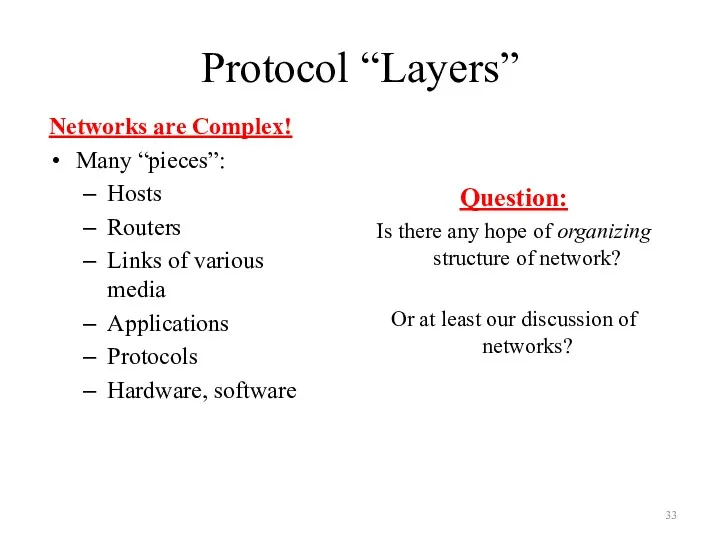
Protocol “Layers”
Networks are Complex!
Many “pieces”:
Hosts
Routers
Links of various media
Applications
Protocols
Hardware, software
Question:
Is
Protocol “Layers”
Networks are Complex!
Many “pieces”:
Hosts
Routers
Links of various media
Applications
Protocols
Hardware, software
Question:
Is
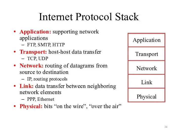
Internet Protocol Stack
Application: supporting network applications
FTP, SMTP, HTTP
Transport: host-host data transfer
TCP,
Internet Protocol Stack
Application: supporting network applications
FTP, SMTP, HTTP
Transport: host-host data transfer
TCP,
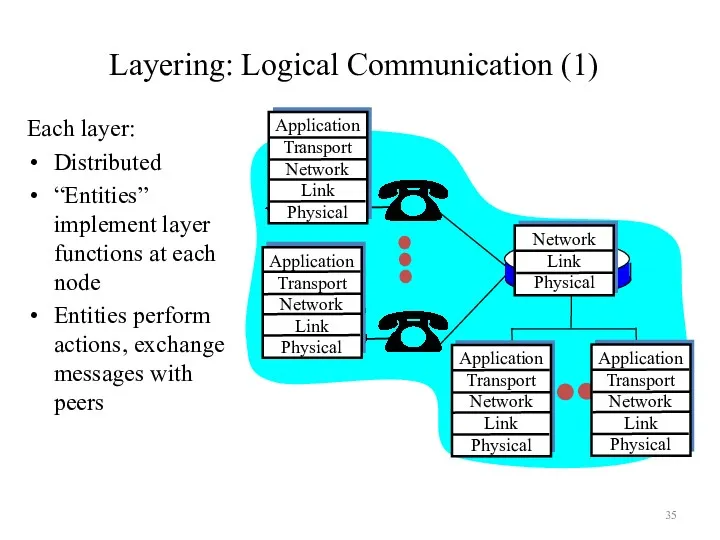
Layering: Logical Communication (1)
Each layer:
Distributed
“Entities” implement layer functions at each
Layering: Logical Communication (1)
Each layer:
Distributed
“Entities” implement layer functions at each
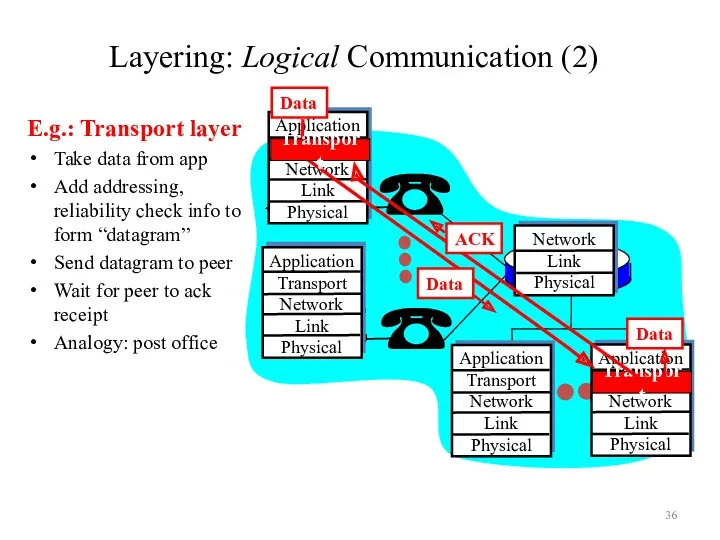
Layering: Logical Communication (2)
E.g.: Transport layer
Take data from app
Add addressing, reliability
Layering: Logical Communication (2)
E.g.: Transport layer
Take data from app
Add addressing, reliability
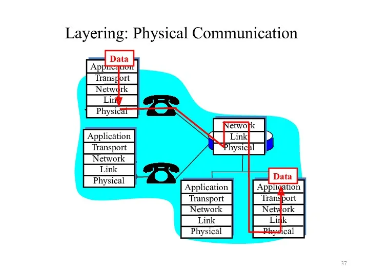
Layering: Physical Communication
Layering: Physical Communication
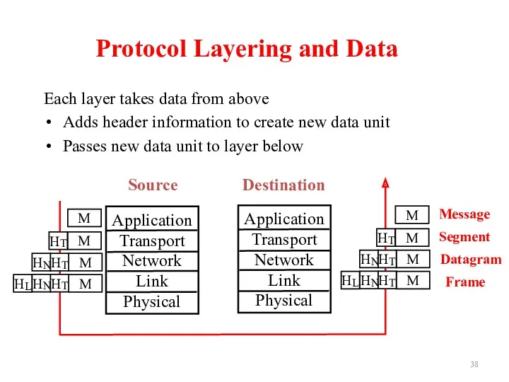
Protocol Layering and Data
Each layer takes data from above
Adds header information
Protocol Layering and Data
Each layer takes data from above
Adds header information
Outline
What is the Internet?
Network Edge
Network Core
Delay, Loss, Throughput in Networks
Protocol Layers,
Outline
What is the Internet?
Network Edge
Network Core
Delay, Loss, Throughput in Networks
Protocol Layers,
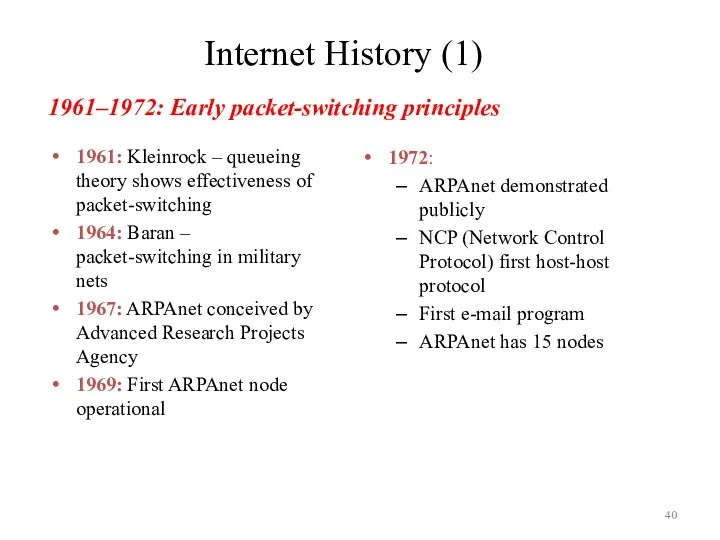
Internet History (1)
1961: Kleinrock – queueing theory shows effectiveness of packet-switching
1964:
Internet History (1)
1961: Kleinrock – queueing theory shows effectiveness of packet-switching
1964:
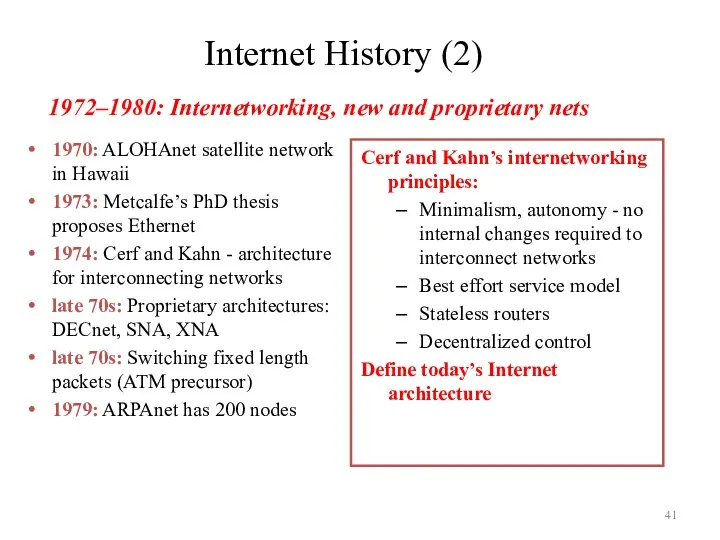
Internet History (2)
1970: ALOHAnet satellite network in Hawaii
1973: Metcalfe’s PhD thesis
Internet History (2)
1970: ALOHAnet satellite network in Hawaii
1973: Metcalfe’s PhD thesis
Internet History (3)
1983: Deployment of TCP/IP
1982: SMTP e-mail protocol defined
1983:
Internet History (3)
1983: Deployment of TCP/IP
1982: SMTP e-mail protocol defined
1983:
Internet History (4)
Early 1990’s: ARPAnet decommissioned
1991: NSF lifts restrictions on commercial
Internet History (4)
Early 1990’s: ARPAnet decommissioned
1991: NSF lifts restrictions on commercial
 Электронное портфолио
 Программирование на языке Паскаль. Символьные строки
 Информационная безопасность. Документооборот. (Лекция 8)
 Техническое задание: основные разделы согласно стандартам. ГОСТ 34.602-89
 Фоноқұжаттар
 Карта знань
 Custom Settings and Custom Metadata Types
 Подходы к решению проблемы импортозамещения в администрации г. Братска
 Исполнитель чертёжник
 Локальные сети
 Электронное землеустройство
 Файлова система NTFS
 Spring Framework. Связи между объектами
 Модели данных. Реляционная модель данных (лекция 6)
 Массивы символов в С++. Прикладное программирование
 Безопасное сетевое взаимодействие. Протокол TLS/SSL
 Логические основы компьютеров
 Объекты окружающего мира. Объекты и множества. Объекты изучения в информатике. Признаки объектов
 Материалы к обсуждению Искусственный интеллект: онтологический и социальный аспекты
 Operating systems. Threads. (Section 4)
 Инструментальные средства верификации и тестирования
 Форматирование текста в текстовом редакторе MS Word
 Б-деревья. Лекция 19
 Личный кабинет студента ПсковГУ. Работа администратора
 Триггеры в презентации. Применение. Создание слайдов с триггерами
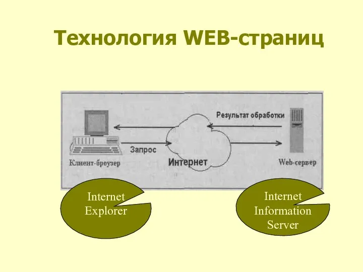 Технология WEB страниц
 Компьютерные игры-симуляторы
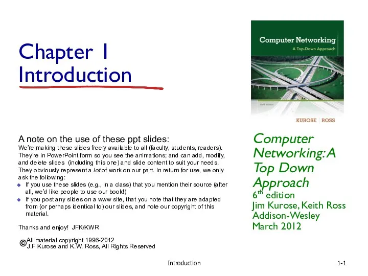 Introduction. Chapter 1