- CM MU(μ) Engine

Содержание
- 2. P/S Pump Auto-tensioner Driving Belt (Serpentine Belt) Alternator A/C Compressor Oil filter VIS 1 Oxygen Sensor
- 3. ETC PCSV PCV Hose CVVT WCC ECT sensor Rear View
- 4. Ignition Coil Delivery Pipe ETC VIS MAP CVVT Top View
- 5. Specification
- 6. Comparison between Delta and Mu
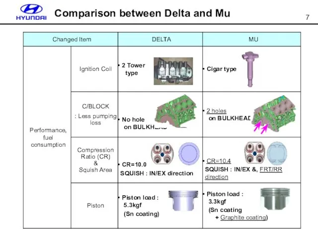
- 7. Comparison between Delta and Mu
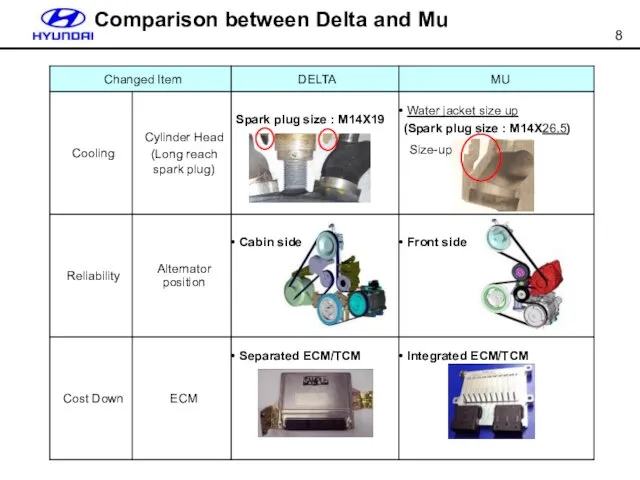
- 8. Comparison between Delta and Mu Size-up
- 9. Comparison between Delta and Mu
- 10. ▶ Press Fit type liner (Aluminum block) ▶ 2 Ventilation Hall – Decreased pumping loss 2
- 11. ▶ Oil circuit for CVVT (Improved response) ▶ Oil circuit for chain tensioner Oil Circuit Cylinder
- 12. ▶ Changed Water Jacket : Improved a cooling efficiency ( Increased valve durability) * LRSP :
- 13. ▶ Connected crankshaft and exhaust camshafts ▶ Timing Belt – Improved durability and reduced noise Timing
- 14. ▶ Connected with crankshaft ▶ Oil pressure at idle (hot condition) : around 1 bar ▶
- 15. ▶ - When replacing engine oil, washer must be replaced together (Supplied oil filter and washer
- 16. Camshaft cap LI1 IN : I EX : E CAP No. LH : L RH :
- 17. 0 120 240 -120 -240 EXHAUST INTAKE 45CA OVERLAP 51CA CVVT – Valve Timing
- 18. 45 CA 4 60 41 15 10 46 CVVT – Valve Timing Comparision 53 CA 14
- 19. Fuel System – RLFS Fuel filter Regulator Fuel pump Damper Fuel rail Injector Sub suction Separator
- 20. EMS Control
- 21. EMS General Specification
- 22. Cooling Fan Control Control logic ■ Fan logic of a vehicle without A/CON is equal to
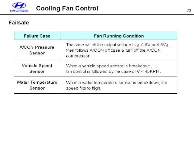
- 23. Cooling Fan Control Failsafe
- 24. EMS Components Parts List
- 25. EMS Components Parts List
- 26. EMS Components Parts List For Mu enigine
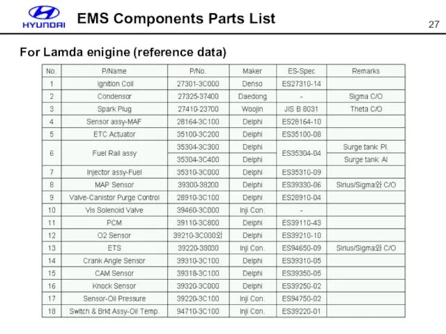
- 27. EMS Components Parts List For Lamda enigine (reference data)
- 28. PCM MAF Sensor Outputs Injector IAT Sensor WTS CKP Sensor CMP Sensor Inputs TPS ETC Relays(Main/Pump/Fan)
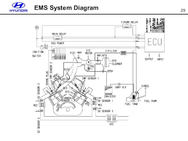
- 29. EMS System Diagram
- 30. CMPS CKPS WTS KNOCK Sensor OPS MAPS OTS O2 Sensor PCSV VIS SOL #2 ETC IG
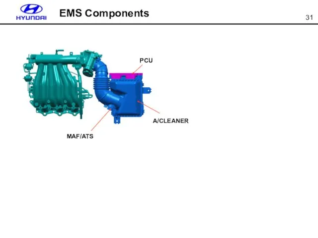
- 31. EMS Components
- 32. ETC( Electronic Throttle Control) system consists of ETC DC motor, throttle body, throttle position sensor and
- 33. Position sensor Motor Drive Position Feedback (TPS1,2) PCM APS1,2 Electronic Throttle Body Driver’s intension ETC System
- 34. Construction
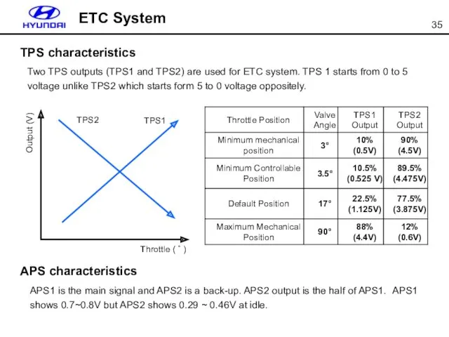
- 35. ETC System TPS characteristics Two TPS outputs (TPS1 and TPS2) are used for ETC system. TPS
- 36. ETC System - TPS Pin assignment
- 37. ETC System - APS APS 4 6 2 5 3 1 Pin assignment APS
- 38. Failsafe There are four main limphome functions in Delphi EMS - Forced idle - Limited performance
- 39. Failsafe Unlike forced idle, power management is followed mainly from TPS failure. Since now ECM doesn’t
- 40. ETC System - Initializing Every time when you make ignition on, ETC goes to initializing for
- 41. ETC System - Power Management
- 42. VIS (Variable Intake System) VIS-2 VIS-1 ■ VIS-1 : for low/middle rpm range ■ VIS-2 :
- 43. System layout VIS (Variable Intake System)
- 44. Solenoid Technical feature - Type : 3 way valve - Coil resistance : 32±3 Ω (at
- 45. Construction VIS (Variable Intake System) Vacuum chamber Manifold valve
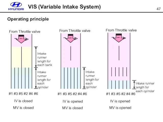
- 46. Operating principle VIS (Variable Intake System)
- 47. IV is closed MV is closed IV is opened MV is closed IV is opened MV
- 48. Control logic Initial position ? Both valve for IV & MV is closed(at no power supply)
- 49. Solenoid output (Sudden acceleration) Solenoid_VIS1 (Interference valve) ON OFF OFF ON Solenoid_VIS2 (Manifold valve) a b
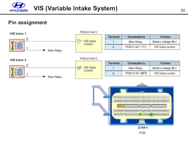
- 50. VIS (Variable Intake System) Pin assignment
- 51. Spark Plug (long reach type) Advantages of long reach spark plug - Better anti-knocking function -
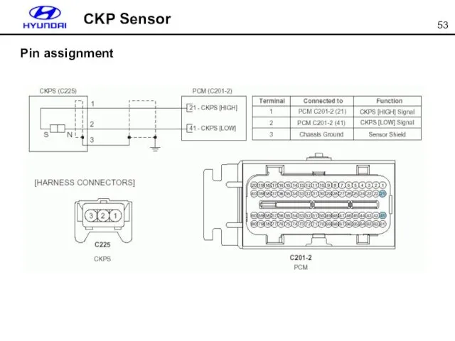
- 52. CKP Sensor - Output voltage : 0.4V~200V - Available engine rpm : 55~7000 rpm - Air
- 53. CKP Sensor Pin assignment
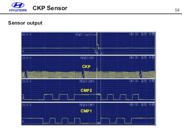
- 54. CKP Sensor Sensor output CKP CMP2 CMP1
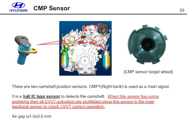
- 55. CMP Sensor There are two camshaft position sensors. CMP1(Right bank) is used as a main signal.
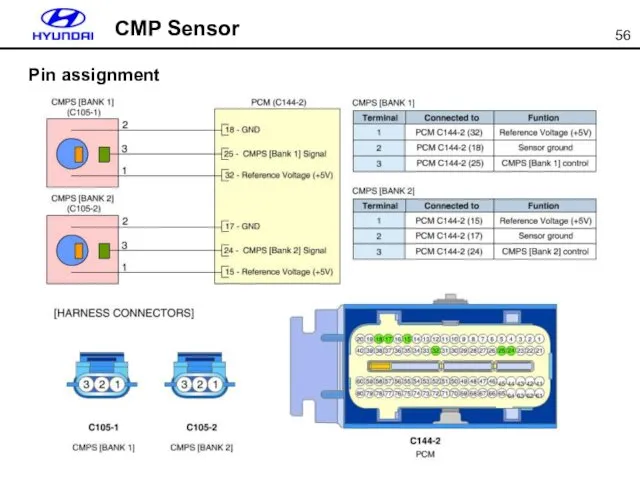
- 56. CMP Sensor Pin assignment
- 57. Technical Feature - Type : NTC thermistor - Operating Temp.: -40℃~130℃ - Resistance : -20℃ :
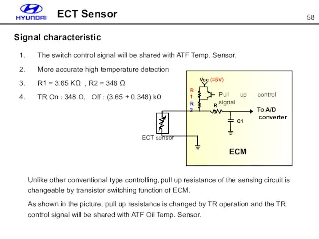
- 58. ECT Sensor The switch control signal will be shared with ATF Temp. Sensor. More accurate high
- 59. PCM controls the switching TR according to the temperature condition. 1) ECT ≤ 50 ˚C, OTS
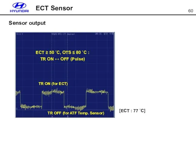
- 60. ECT Sensor Sensor output ECT ≥ 50 ˚C, OTS ≤ 80 ˚C : TR ON ↔
- 61. ECT Sensor Pin assignment
- 62. MAF sensor outputs frequency (Hz) according to the intake air amount. Frequency generator is assembled in
- 63. MAF Sensor Output characteristics Sudden acceleration Idle
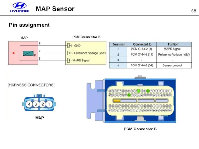
- 64. When MAP sensor is normal : replaced by MAP sensor When MAP sensor is failed :
- 65. MAF Sensor Pin assignment
- 66. MAP Sensor MAP (Manifold Absolute Pressure) sensor is installed on the surge tank. It detects the
- 67. Cover Bush O-Ring NTC Thermistor Housing Ass’y MAP Sensor Sensor Type : Piezo Resistive Pressure range
- 68. MAP Sensor Pin assignment
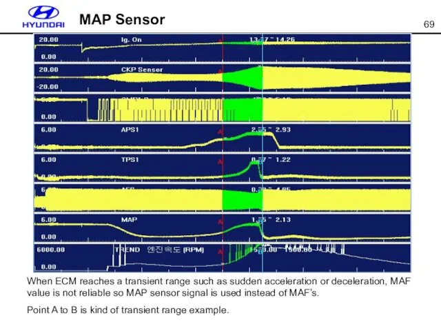
- 69. MAP Sensor When ECM reaches a transient range such as sudden acceleration or deceleration, MAF value
- 70. MAP Sensor Failsafe [[When MAP sensor connector is open]
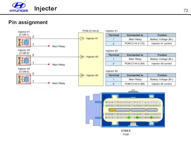
- 71. Technical features EV6 (Kefico) : 4 Hole, 2 Spray Flow rate: 150g/min Spray Pattern - Cone
- 72. Injecter Pin assignment
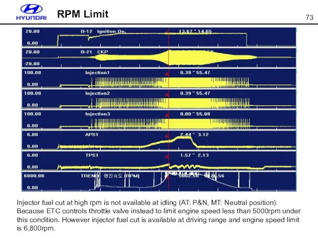
- 73. RPM Limit Injector fuel cut at high rpm is not available at idling (AT: P&N, MT:
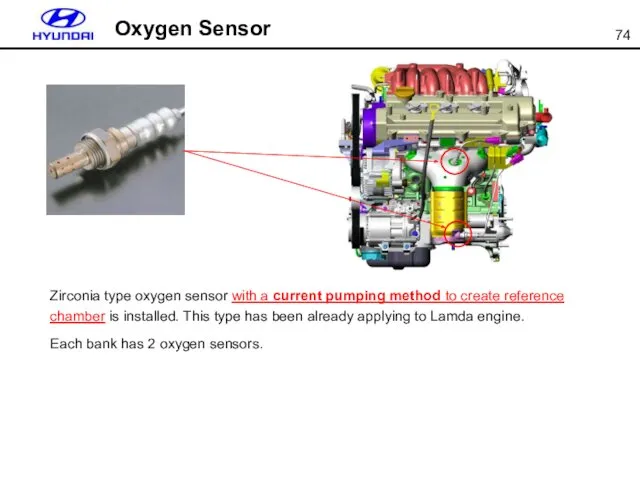
- 74. Oxygen Sensor Zirconia type oxygen sensor with a current pumping method to create reference chamber is
- 75. Oxygen Sensor When ECM supply current through signal output line which is about 7 ~ 10
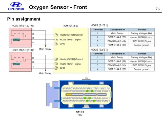
- 76. Oxygen Sensor - Front Pin assignment
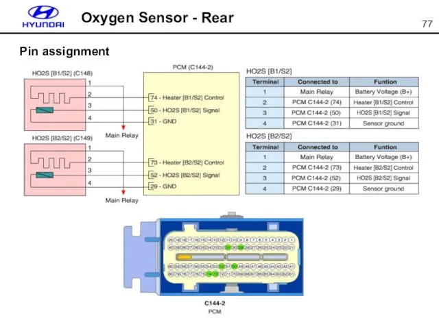
- 77. Oxygen Sensor - Rear Pin assignment
- 78. Oxygen Sensor Even reference chamber is created by electrically, oxygen sensor waveform is same as the
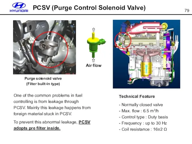
- 79. PCSV (Purge Control Solenoid Valve) Purge solenoid valve (Filter built-in type) One of the common problems
- 80. Knock Sensor When knock is detected, ECM retards the ignition timing to certain range. If knocking
- 81. Knock Sensor Sensor output 1.6V [Knock sensor output at engine idle]
- 82. Knock Sensor Pin assignment
- 83. Oil Temp. Sensor Technical feature - Type : NTC thermistor - Operating Temp. : -40℃ ~170℃
- 84. Oil Temp. Sensor Pin assignment
- 86. Скачать презентацию
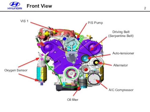
P/S Pump
Auto-tensioner
Driving Belt (Serpentine Belt)
Alternator
A/C Compressor
Oil filter
VIS 1
Oxygen Sensor
Front View
P/S Pump
Auto-tensioner
Driving Belt (Serpentine Belt)
Alternator
A/C Compressor
Oil filter
VIS 1
Oxygen Sensor
Front View
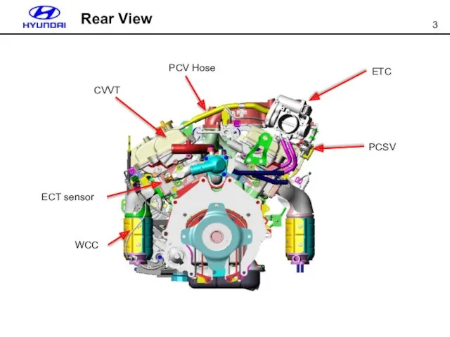
ETC
PCSV
PCV Hose
CVVT
WCC
ECT sensor
Rear View
ETC
PCSV
PCV Hose
CVVT
WCC
ECT sensor
Rear View
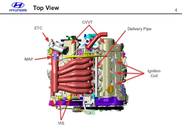
Ignition Coil
Delivery Pipe
ETC
VIS
MAP
CVVT
Top View
Ignition Coil
Delivery Pipe
ETC
VIS
MAP
CVVT
Top View
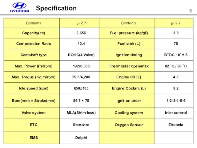
Specification
Specification
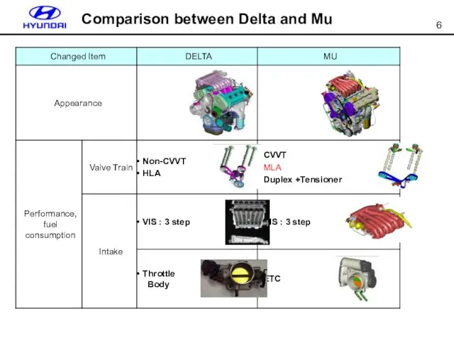
Comparison between Delta and Mu
Comparison between Delta and Mu
Comparison between Delta and Mu
Comparison between Delta and Mu
Comparison between Delta and Mu
Size-up
Comparison between Delta and Mu
Size-up
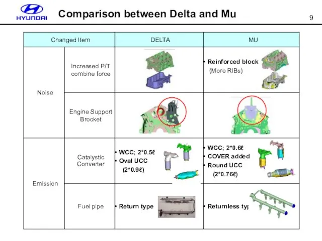
Comparison between Delta and Mu
Comparison between Delta and Mu
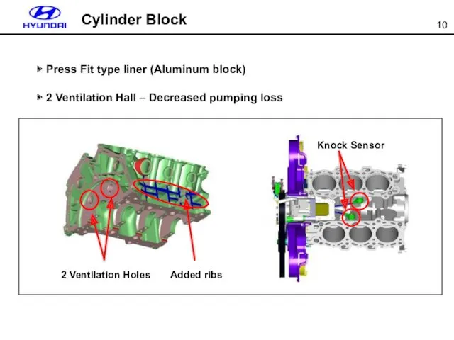
▶ Press Fit type liner (Aluminum block)
▶ 2 Ventilation Hall
▶ Press Fit type liner (Aluminum block)
▶ 2 Ventilation Hall
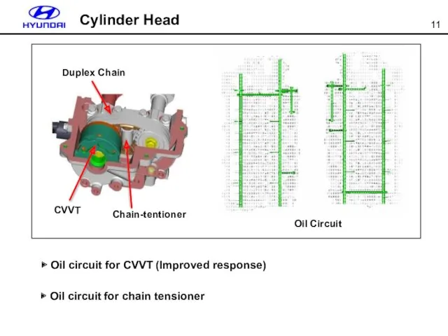
▶ Oil circuit for CVVT (Improved response)
▶ Oil circuit for chain
▶ Oil circuit for CVVT (Improved response)
▶ Oil circuit for chain

▶ Changed Water Jacket : Improved a cooling efficiency
( Increased
▶ Changed Water Jacket : Improved a cooling efficiency
( Increased
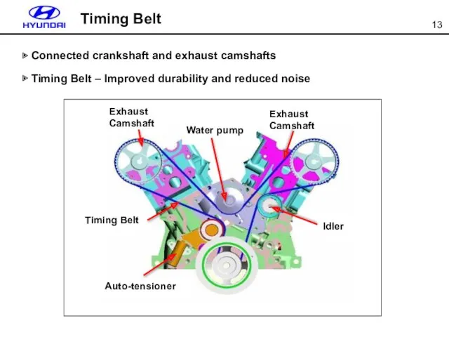
▶ Connected crankshaft and exhaust camshafts
▶ Timing Belt – Improved durability
▶ Connected crankshaft and exhaust camshafts
▶ Timing Belt – Improved durability
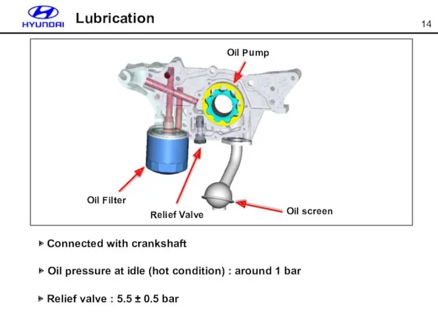
▶ Connected with crankshaft
▶ Oil pressure at idle (hot condition) :
▶ Connected with crankshaft
▶ Oil pressure at idle (hot condition) :
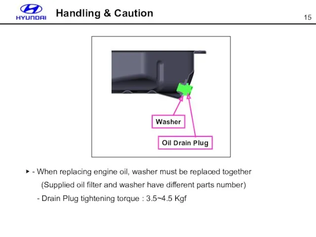
▶ - When replacing engine oil, washer must be replaced together
▶ - When replacing engine oil, washer must be replaced together

Camshaft cap
LI1
IN : I
EX : E
CAP No.
LH : L
RH :
Camshaft cap
LI1
IN : I
EX : E
CAP No.
LH : L
RH :

0
120
240
-120
-240
EXHAUST
INTAKE
45CA
OVERLAP 51CA
CVVT – Valve Timing
0
120
240
-120
-240
EXHAUST
INTAKE
45CA
OVERLAP 51CA
CVVT – Valve Timing
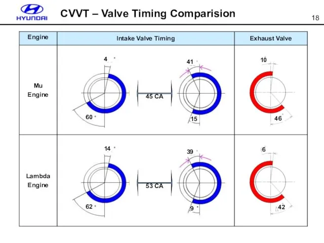
45 CA
4
60
41
15
10
46
CVVT – Valve Timing Comparision
53 CA
14
62
39
9
6
42
45 CA
4
60
41
15
10
46
CVVT – Valve Timing Comparision
53 CA
14
62
39
9
6
42
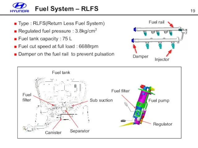
Fuel System – RLFS
Fuel filter
Regulator
Fuel pump
Damper
Fuel System – RLFS
Fuel filter
Regulator
Fuel pump
Damper
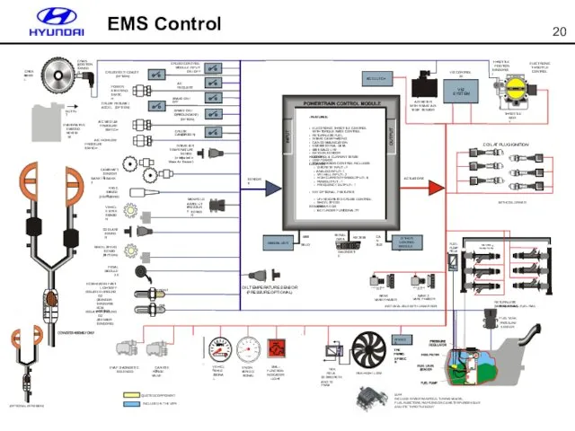
EMS Control
EMS Control

EMS General
Specification
EMS General
Specification

Cooling Fan Control
Control logic
■ Fan logic of a vehicle without A/CON
Cooling Fan Control
Control logic
■ Fan logic of a vehicle without A/CON
Cooling Fan Control
Failsafe
Cooling Fan Control
Failsafe
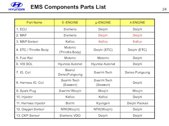
EMS Components Parts List
EMS Components Parts List
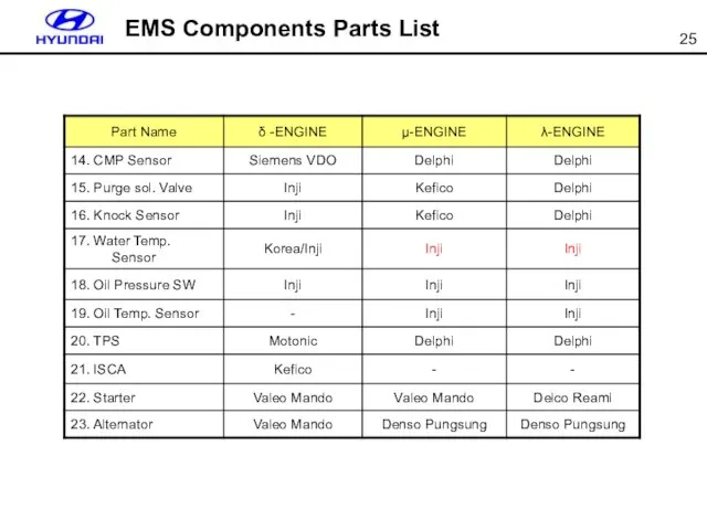
EMS Components Parts List
EMS Components Parts List
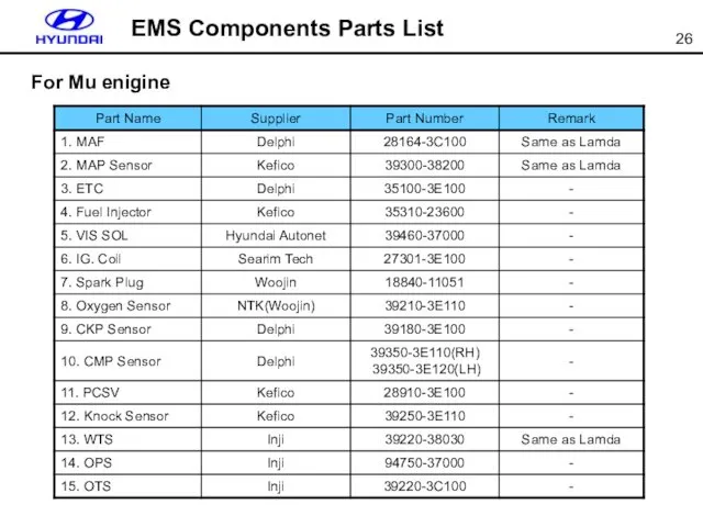
EMS Components Parts List
For Mu enigine
EMS Components Parts List
For Mu enigine
EMS Components Parts List
For Lamda enigine (reference data)
EMS Components Parts List
For Lamda enigine (reference data)

PCM
MAF Sensor
Outputs
Injector
IAT Sensor
WTS
CKP Sensor
CMP Sensor
Inputs
TPS
ETC
Relays(Main/Pump/Fan)
PCSV
Ignition Coil
APS
O2 Sensor
Knock
PCM
MAF Sensor
Outputs
Injector
IAT Sensor
WTS
CKP Sensor
CMP Sensor
Inputs
TPS
ETC
Relays(Main/Pump/Fan)
PCSV
Ignition Coil
APS
O2 Sensor
Knock
EMS System Diagram
EMS System Diagram

CMPS
CKPS
WTS
KNOCK Sensor
OPS
MAPS
OTS
O2 Sensor
PCSV
VIS SOL #2
ETC
IG COIL
Alteranator
EMS Components
VIS SOL #1
CMPS
CKPS
WTS
KNOCK Sensor
OPS
MAPS
OTS
O2 Sensor
PCSV
VIS SOL #2
ETC
IG COIL
Alteranator
EMS Components
VIS SOL #1
EMS Components
EMS Components
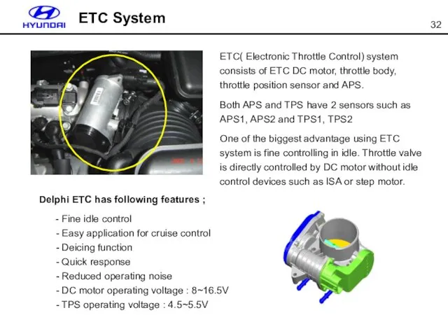
ETC( Electronic Throttle Control) system consists of ETC DC motor, throttle
ETC( Electronic Throttle Control) system consists of ETC DC motor, throttle
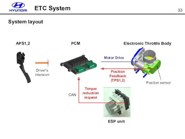
Position sensor
Motor Drive
Position Feedback (TPS1,2)
PCM
APS1,2
Electronic Throttle Body
Driver’s intension
ETC System
System layout
CAN
ESP unit
Torque
Position sensor
Motor Drive
Position Feedback (TPS1,2)
PCM
APS1,2
Electronic Throttle Body
Driver’s intension
ETC System
System layout
CAN
ESP unit
Torque
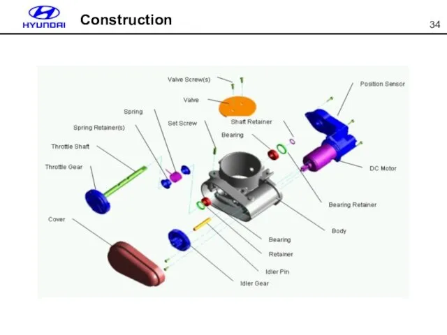
Construction
Construction
ETC System
TPS characteristics
Two TPS outputs (TPS1 and TPS2) are used
ETC System
TPS characteristics
Two TPS outputs (TPS1 and TPS2) are used

ETC System - TPS
Pin assignment
ETC System - TPS
Pin assignment

ETC System - APS
APS
4
6
2
5
3
1
Pin assignment
APS
ETC System - APS
APS
4
6
2
5
3
1
Pin assignment
APS

Failsafe
There are four main limphome functions in Delphi EMS
- Forced
Failsafe
There are four main limphome functions in Delphi EMS
- Forced

Failsafe
Unlike forced idle, power management is followed mainly from TPS failure.
Failsafe
Unlike forced idle, power management is followed mainly from TPS failure.

ETC System - Initializing
Every time when you make ignition on, ETC
ETC System - Initializing
Every time when you make ignition on, ETC
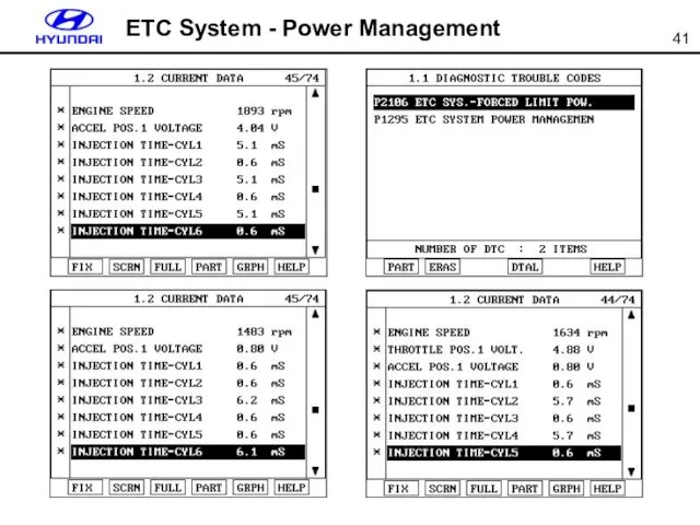
ETC System - Power Management
ETC System - Power Management

VIS (Variable Intake System)
VIS-2
VIS-1
■ VIS-1 : for low/middle rpm range
■
VIS (Variable Intake System)
VIS-2
VIS-1
■ VIS-1 : for low/middle rpm range
■
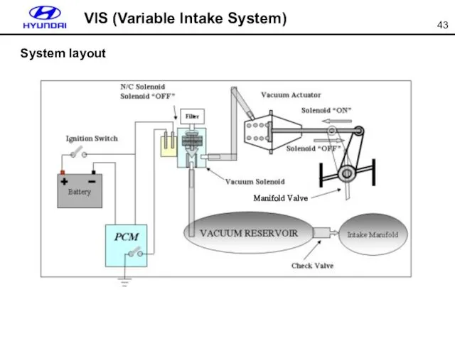
System layout
VIS (Variable Intake System)
System layout
VIS (Variable Intake System)
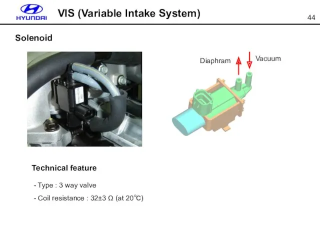
Solenoid
Technical feature
- Type : 3 way valve
- Coil resistance
Solenoid
Technical feature
- Type : 3 way valve
- Coil resistance
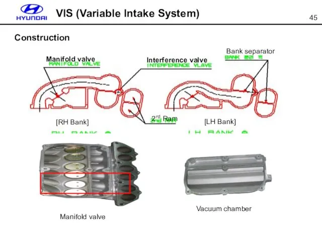
Construction
VIS (Variable Intake System)
Vacuum chamber
Manifold valve
Construction
VIS (Variable Intake System)
Vacuum chamber
Manifold valve
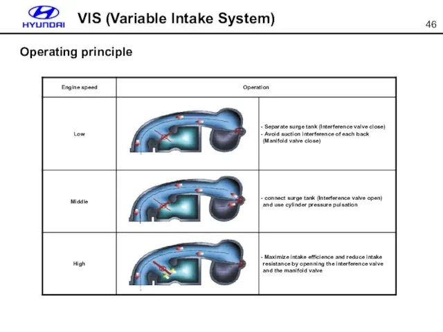
Operating principle
VIS (Variable Intake System)
Operating principle
VIS (Variable Intake System)
IV is closed
MV is closed
IV is opened
MV is closed
IV is opened
MV
IV is closed
MV is closed
IV is opened
MV is closed
IV is opened
MV

Control logic
Initial position ? Both valve for IV &
Control logic
Initial position ? Both valve for IV &
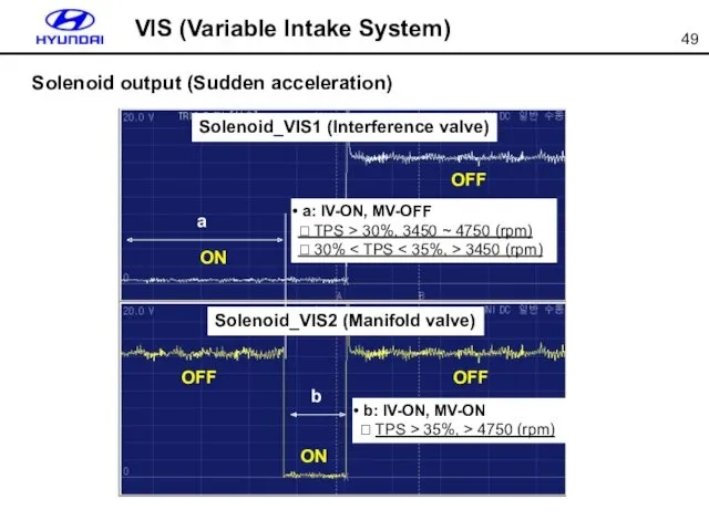
Solenoid output (Sudden acceleration)
Solenoid_VIS1 (Interference valve)
ON
OFF
OFF
ON
Solenoid_VIS2 (Manifold valve)
a
b
a: IV-ON, MV-OFF
?
Solenoid output (Sudden acceleration)
Solenoid_VIS1 (Interference valve)
ON
OFF
OFF
ON
Solenoid_VIS2 (Manifold valve)
a
b
a: IV-ON, MV-OFF ?
VIS (Variable Intake System)
Pin assignment
VIS (Variable Intake System)
Pin assignment
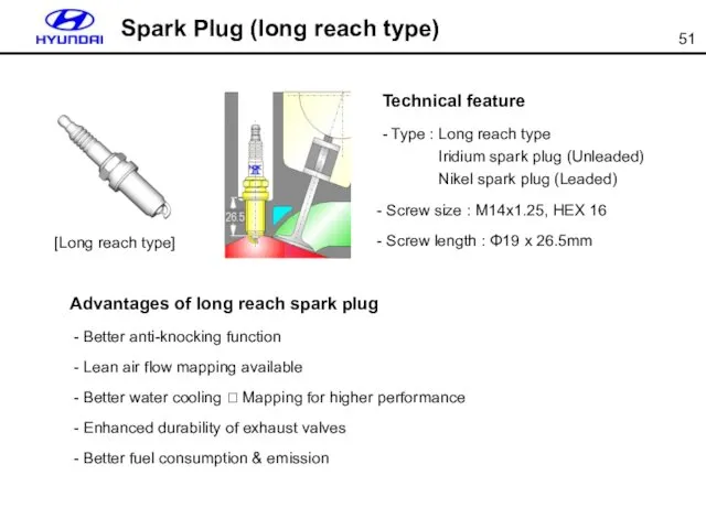
Spark Plug (long reach type)
Advantages of long reach spark plug
-
Spark Plug (long reach type)
Advantages of long reach spark plug
-

CKP Sensor
- Output voltage : 0.4V~200V
- Available engine rpm
CKP Sensor
- Output voltage : 0.4V~200V - Available engine rpm
CKP Sensor
Pin assignment
CKP Sensor
Pin assignment
CKP Sensor
Sensor output
CKP
CMP2
CMP1
CKP Sensor
Sensor output
CKP
CMP2
CMP1
CMP Sensor
There are two camshaft position sensors. CMP1(Right bank) is used
CMP Sensor
There are two camshaft position sensors. CMP1(Right bank) is used
CMP Sensor
Pin assignment
CMP Sensor
Pin assignment

Technical Feature
- Type : NTC thermistor
- Operating Temp.: -40℃~130℃
Technical Feature
- Type : NTC thermistor
- Operating Temp.: -40℃~130℃
ECT Sensor
The switch control signal will be shared with ATF Temp.
ECT Sensor
The switch control signal will be shared with ATF Temp.
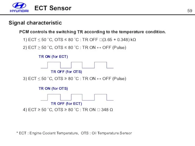
PCM controls the switching TR according to the temperature condition.
1)
PCM controls the switching TR according to the temperature condition. 1)
ECT Sensor
Sensor output
ECT ≥ 50 ˚C, OTS ≤ 80 ˚C :
ECT Sensor
Sensor output
ECT ≥ 50 ˚C, OTS ≤ 80 ˚C :
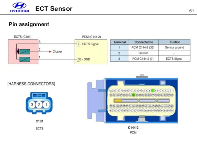
ECT Sensor
Pin assignment
ECT Sensor
Pin assignment
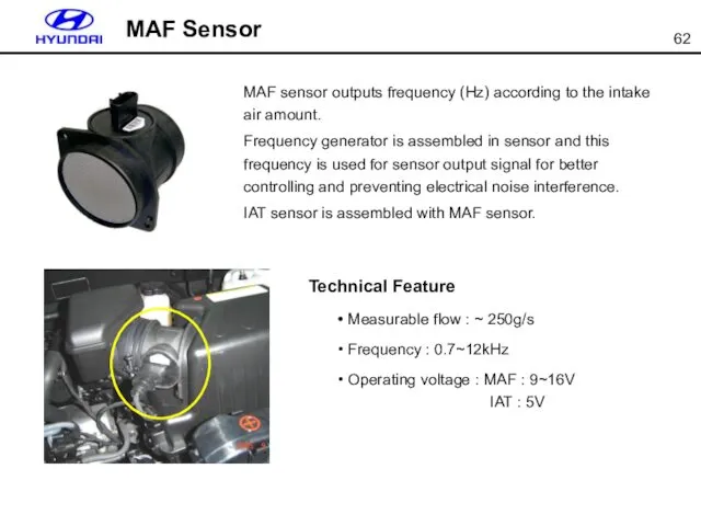
MAF sensor outputs frequency (Hz) according to the intake air amount.
Frequency
MAF sensor outputs frequency (Hz) according to the intake air amount.
Frequency
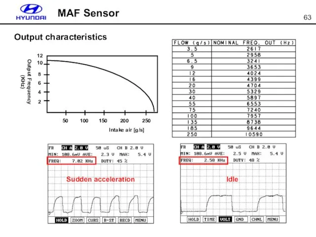
MAF Sensor
Output characteristics
Sudden acceleration
Idle
MAF Sensor
Output characteristics
Sudden acceleration
Idle

When MAP sensor is normal : replaced by MAP sensor
When MAP
When MAP sensor is normal : replaced by MAP sensor
When MAP
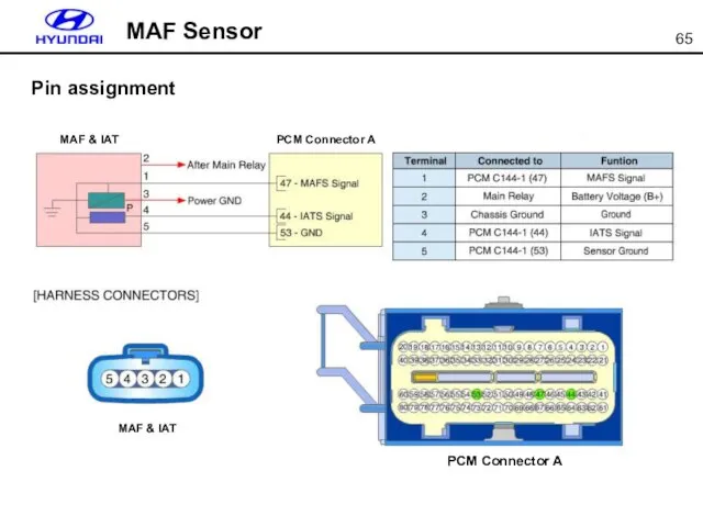
MAF Sensor
Pin assignment
MAF Sensor
Pin assignment
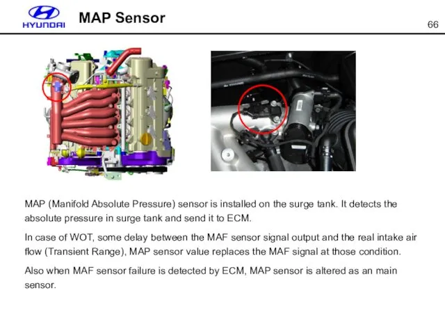
MAP Sensor
MAP (Manifold Absolute Pressure) sensor is installed on the surge
MAP Sensor
MAP (Manifold Absolute Pressure) sensor is installed on the surge

Cover
Bush
O-Ring
NTC Thermistor
Housing Ass’y
MAP Sensor
Sensor Type :
Cover
Bush
O-Ring
NTC Thermistor
Housing Ass’y
MAP Sensor
Sensor Type :
MAP Sensor
Pin assignment
MAP Sensor
Pin assignment
MAP Sensor
When ECM reaches a transient range such as sudden acceleration
MAP Sensor
When ECM reaches a transient range such as sudden acceleration
![MAP Sensor Failsafe [[When MAP sensor connector is open]](/_ipx/f_webp&q_80&fit_contain&s_1440x1080/imagesDir/jpg/96005/slide-69.jpg)
MAP Sensor
Failsafe
[[When MAP sensor connector is open]
MAP Sensor
Failsafe
[[When MAP sensor connector is open]

Technical features
EV6 (Kefico) : 4 Hole, 2 Spray
Flow rate:
Technical features
EV6 (Kefico) : 4 Hole, 2 Spray
Flow rate:
Injecter
Pin assignment
Injecter
Pin assignment
RPM Limit
Injector fuel cut at high rpm is not available at
RPM Limit
Injector fuel cut at high rpm is not available at
Oxygen Sensor
Zirconia type oxygen sensor with a current pumping method to
Oxygen Sensor
Zirconia type oxygen sensor with a current pumping method to

Oxygen Sensor
When ECM supply current through signal output line which is
Oxygen Sensor
When ECM supply current through signal output line which is
Oxygen Sensor - Front
Pin assignment
Oxygen Sensor - Front
Pin assignment
Oxygen Sensor - Rear
Pin assignment
Oxygen Sensor - Rear
Pin assignment

Oxygen Sensor
Even reference chamber is created by electrically, oxygen sensor waveform
Oxygen Sensor
Even reference chamber is created by electrically, oxygen sensor waveform
PCSV (Purge Control Solenoid Valve)
Purge solenoid valve
(Filter built-in type)
One of
PCSV (Purge Control Solenoid Valve)
Purge solenoid valve
(Filter built-in type)
One of
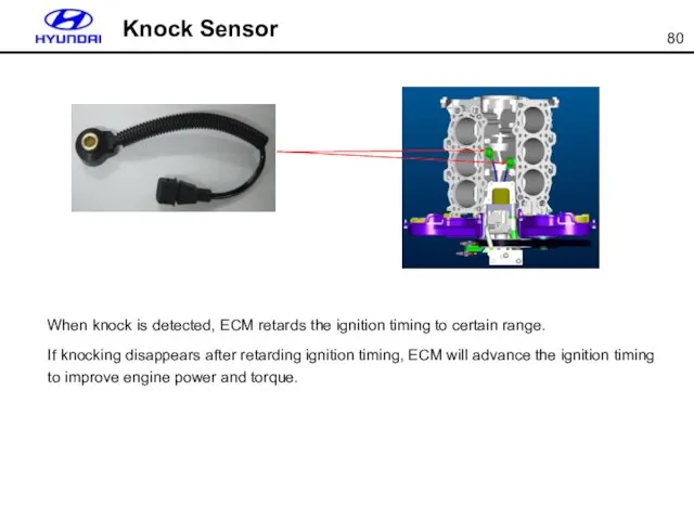
Knock Sensor
When knock is detected, ECM retards the ignition timing to
Knock Sensor
When knock is detected, ECM retards the ignition timing to
![Knock Sensor Sensor output 1.6V [Knock sensor output at engine idle]](/_ipx/f_webp&q_80&fit_contain&s_1440x1080/imagesDir/jpg/96005/slide-80.jpg)
Knock Sensor
Sensor output
1.6V
[Knock sensor output at engine idle]
Knock Sensor
Sensor output
1.6V
[Knock sensor output at engine idle]
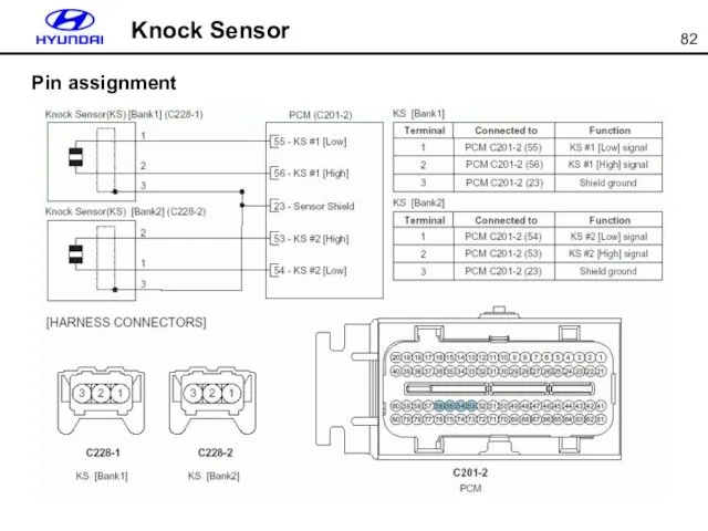
Knock Sensor
Pin assignment
Knock Sensor
Pin assignment
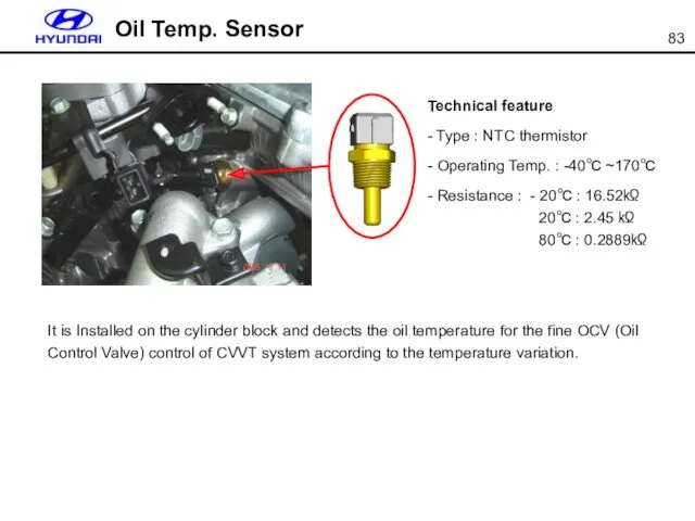
Oil Temp. Sensor
Technical feature
- Type : NTC thermistor
- Operating Temp. :
Oil Temp. Sensor
Technical feature
- Type : NTC thermistor
- Operating Temp. :
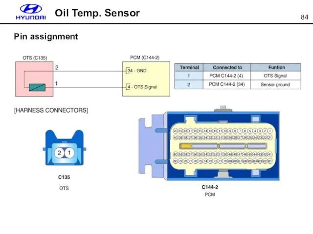
Oil Temp. Sensor
Pin assignment
Oil Temp. Sensor
Pin assignment
 Advertisement. Packing
 Мировые тренды на керамическую плитку
 Исследование рыночного спроса на продукцию предприятия
 Вихідні відомості журналу
 Каталог мастер-классов Пасха
 Квалификационная (дипломная) работа Проведение исследования поведения потребителей на рынке (на примере ИП Ларшина Е.А.)
 Хирургиялық стоматологиядағы менеджмент және маркетинг
 Microbus love
 Оздоровительный туризм Вьетнама
 Маркетинг в социальных сетях
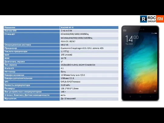 XIAOMI Redmi Note 3, XIAOMI Redmi 3 Pro, XIAOMI Redmi 2 Pro
 Динамика корпоративного развития Bosch
 Тауар саны бойынша градация
 Міжнародна реклама
 Marketing strategy for the U.S. market
 Товарная политика аптеки в фармацевтическом маркетинге
 Интернет в офис. Коммерческое предложение от Билайн Бизнес
 Комплекс Med Planta (Cosmofarma, Италия)
 OZON. Статусы заказа
 Изменения в ассортименте моторных масел petro-canada для легкового транспорта
 Фирменный стиль
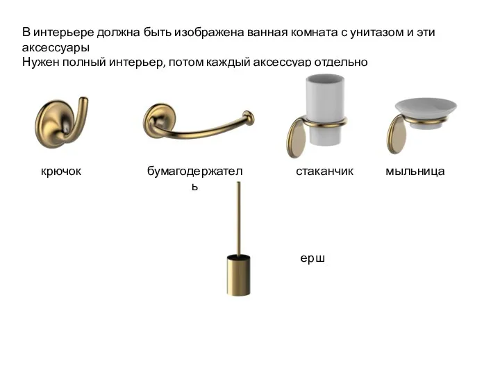 Корректировки. аксессуары для ванной Oldie
 ЖК Новая Ливадия
 Методы оценки кривых спроса
 Медиаплан по продвижению интернет-магазина Mediapark.uz в связи с Covid-19
 Процесс управления маркетинговой деятельностью компании
 Marketing strategy
 Описания Шоу программ