- Workplace Organization. Lean OS Development & Global BOP Team

Содержание
- 2. 1. Workplace Organization Purpose To provide an ergonomic and safe work environment for operators, standardized processes
- 3. 3. Handling & Protection How to Accommodate Components at the Point of Use In order to
- 4. 3. Handling & Protection Summary Matrix 3.2 Wires: 700mm Length: 700mm 1300mm
- 5. 3. Handling & Protection How to Accommodate Wires at the Cutting Supermarket Following the Cutting Guidelines,
- 6. 3. Handling & Protection How to Accommodate Wires at the Point of Use Wire Presentation should
- 7. 3. Handling & Protection How to Accommodate Wires at the Point of Use Short Wires Use
- 8. Physical Separators between Wires 3. Handling & Protection Wires at Point of Use Examples 1. Terminals
- 9. 3. Handling & Protection Wires at Point of Use Examples 6. Terminals Protection from the front
- 10. 3. Handling & Protection Wires at Point of Use Examples 8. Terminals Protection from the back
- 11. 3. Handling & Protection Kits & Recommend Connection Tools
- 12. 3. Handling & Protection Kits & Recommend Connection Tools
- 13. 3. Handling & Protection Kits & Recommend Connection Tools
- 14. Wire Rack Design Criteria: Minimum reaching point for all materials/ Splice / kit/ lead coil is
- 15. Rack Design Concept Example of Europe - Rack Type 3 FRONT VIEW BACK VIEW CUBICAL VIEW
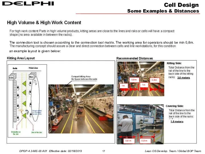
- 16. Cell Design Some Examples & Distances The connection tool is chosen according to the connection tool
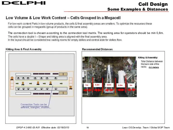
- 17. Cell Design Some Examples & Distances The connection tool is chosen according to the connection tool
- 18. Cell Design Some Examples & Distances The connection tool is chosen according to the connection tool
- 19. Assembly area layout has to support clear material flow and the Visual Management. Address system has
- 20. 5. Standardized Work Impact of the Workplace Organization on the Manpower Results Good WPO can lead
- 22. Скачать презентацию
1. Workplace Organization Purpose
To provide an ergonomic and safe work environment
1. Workplace Organization Purpose
To provide an ergonomic and safe work environment
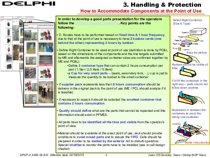
3. Handling & Protection
How to Accommodate Components at the Point of
3. Handling & Protection
How to Accommodate Components at the Point of
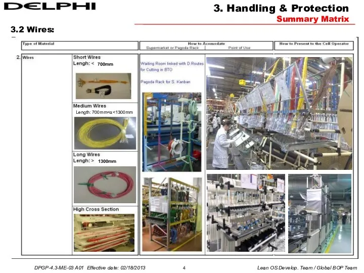
3. Handling & Protection
Summary Matrix
3.2 Wires:
700mm
Length: 700mm<α<1300mm
1300mm
3. Handling & Protection
Summary Matrix
3.2 Wires:
700mm
Length: 700mm<α<1300mm
1300mm
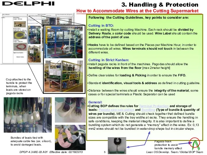
3. Handling & Protection
How to Accommodate Wires at the Cutting Supermarket
Following
3. Handling & Protection
How to Accommodate Wires at the Cutting Supermarket
Following

3. Handling & Protection
How to Accommodate Wires at the Point of
3. Handling & Protection
How to Accommodate Wires at the Point of

3. Handling & Protection
How to Accommodate Wires at the Point of
3. Handling & Protection
How to Accommodate Wires at the Point of

Physical Separators between Wires
3. Handling & Protection
Wires at Point of Use
Physical Separators between Wires
3. Handling & Protection
Wires at Point of Use
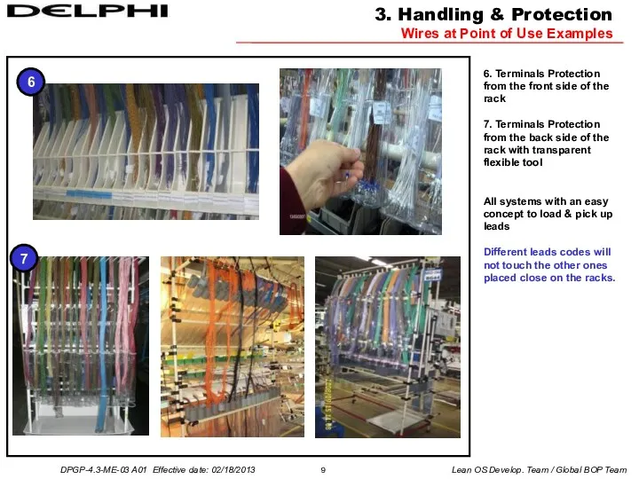
3. Handling & Protection
Wires at Point of Use Examples
6. Terminals Protection
3. Handling & Protection
Wires at Point of Use Examples
6. Terminals Protection

3. Handling & Protection
Wires at Point of Use Examples
8. Terminals Protection
3. Handling & Protection
Wires at Point of Use Examples
8. Terminals Protection
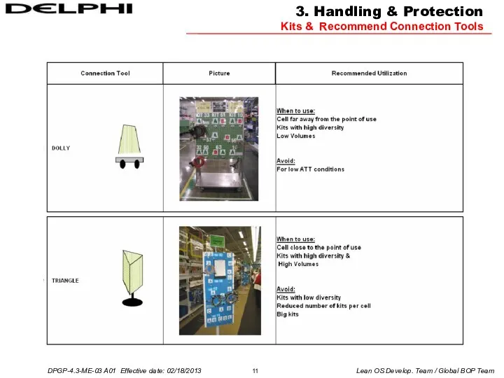
3. Handling & Protection
Kits & Recommend Connection Tools
3. Handling & Protection
Kits & Recommend Connection Tools

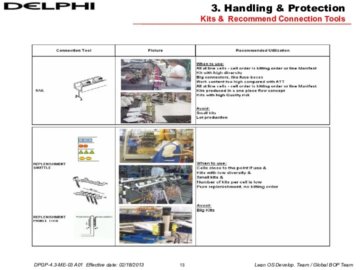
3. Handling & Protection
Kits & Recommend Connection Tools
3. Handling & Protection
Kits & Recommend Connection Tools
3. Handling & Protection
Kits & Recommend Connection Tools
3. Handling & Protection
Kits & Recommend Connection Tools
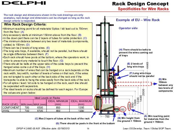
Wire Rack Design Criteria:
Minimum reaching point for all materials/ Splice /
Wire Rack Design Criteria:
Minimum reaching point for all materials/ Splice /

Rack Design Concept
Example of Europe - Rack Type 3
FRONT VIEW
Rack Design Concept
Example of Europe - Rack Type 3
FRONT VIEW

Cell Design
Some Examples & Distances
The connection tool is chosen according to
Cell Design
Some Examples & Distances
The connection tool is chosen according to
Cell Design
Some Examples & Distances
The connection tool is chosen according to
Cell Design
Some Examples & Distances
The connection tool is chosen according to
Cell Design
Some Examples & Distances
The connection tool is chosen according to
Cell Design
Some Examples & Distances
The connection tool is chosen according to
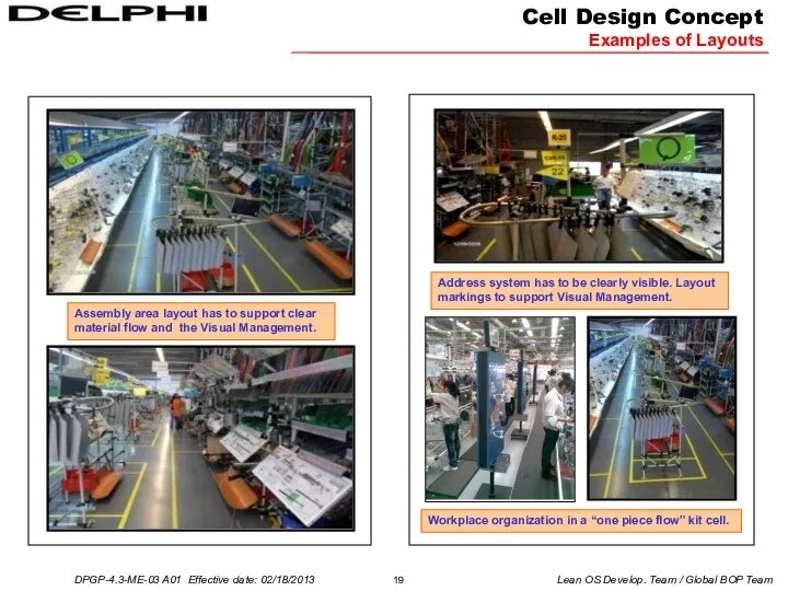
Assembly area layout has to support clear material flow and the
Assembly area layout has to support clear material flow and the
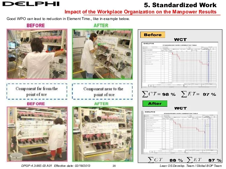
5. Standardized Work
Impact of the Workplace Organization on the Manpower Results
Good
5. Standardized Work
Impact of the Workplace Organization on the Manpower Results
Good
 Организация развлекательных услуг в гостинице
 Комплекс транспортно-экспедиционного обслуживания
 Виды бизнес-процессов. Управление бизнес-процессами
 Институциональное управление проектами
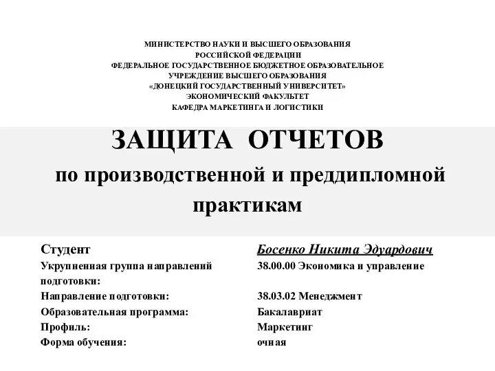 Защита отчетов по производственной и преддипломной практикам. Специальность 38.00.00 Экономика и управление
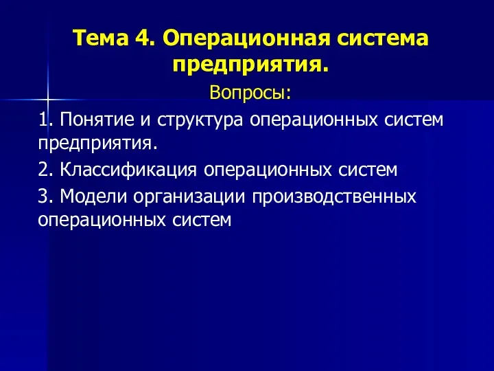 Операционная система предприятия
 Транспортная логистика. (Тема 6)
 Власть и лидерство
 Управление разработкой инновационными проектами. Понятия, основные этапы создания и реализация
 Продажі й обслуговування JYSK Тренінг для персоналу магазину
 Сертифицированный CQI и IRCA курс ведущего аудитора по стандарту ISO 45001 Системы менеджмента охраны здоровья и безопасности
 Диаграмма Исикавы. Рыбий скелет Исикавы
 Базовые понятия современной концепции управления проектом
 Емтихан үстіндегі сенімділік. Сенімділік күш береді
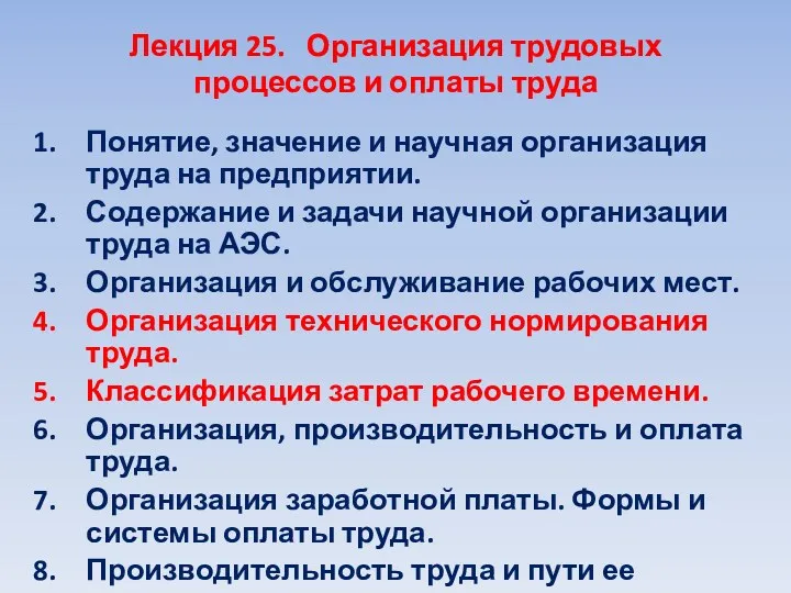 Организация трудовых процессов и оплаты труда. Лекция 25
 Функции управления. Стратегическое планирование, предвидение, прогнозирование. Мотивация. Построение организаций (координация)
 Управление проектами
 Personalo valdymo metodologija
 Аналіз ринку логістичних послуг в Україні
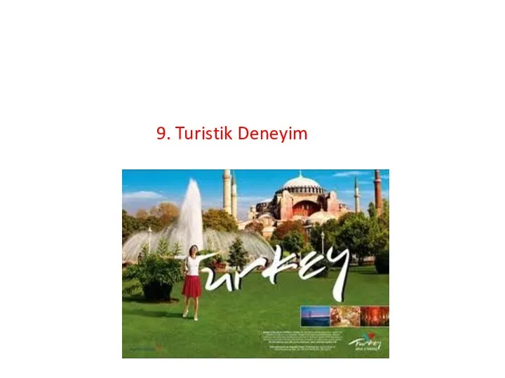 Turistik deneyim
 Работа менеджера. Содержание и базовые модели
 Особенности организации обслуживания потребителей в сельском кафе Лидер
 Организация государственного налогового менеджмента
 Организация труда персонала
 Новое общественное управление
 Инновационный менеджмент
 Swot-анализ. Особенности применения и методология проведени
 Комплекс управленческих мероприятий по повышению эффективности деятельности организации ООО Неаполь