- ACTYON Service Training. Engine : D20DT / D27DT. Engine General

Содержание
- 2. Contents D20DT Engine General Removal & Installation Turbo Charger (VGT) Diagnosis
- 3. 1. Engine Room Description 1. Reservoir Tank 2. FFH(Fuel Fired Heater) 3. Vacuum Pump 4. Brake
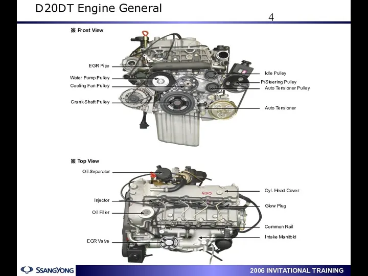
- 4. 2. Engine Structure D20DT Engine General
- 5. D20DT Engine General
- 6. 3. Location of Sensors & Actuators D20DT Engine General
- 7. D20DT Engine General
- 8. 4. Engine Specifications D20DT Engine General
- 9. 5. Engine Performance Curve 1) Horse Power & Torque D20DT Engine General
- 10. 2) Oil Pressure and Temperature & Boost Pressure D20DT Engine General
- 11. 1. Fuel System Tightening Torque ( D27DT / D20DT ) D20DT Engine General
- 12. 2. HP Pump System Tightening Torque (D20DT ) D20DT Engine General
- 13. 1. Components and Special Tools Removal & Installation
- 14. Removal & Installation
- 15. 2. List for Special Tools Removal & Installation
- 16. 1. Turn the auto tensioner counterclockwise and remove the fan belt. 2. Remove the engine belt
- 17. 5. Align the OT mark by rotating the crankshaft. 1) Open the oil filler cap and
- 18. 9. Slacken three HP pump mounting bolts until they contact with the sprocket. 10. Loosen the
- 19. 2. Tighten the HP pump bolts. 3. Tighten the center nut after fixing the sprocket. 1.
- 20. 6. Install auto tensioner and belt pulley. 7. See if timing marks are aligned after rotating
- 21. ① When installing/removing of chain or sprocket, must align the timing mark “▶” and copper mark
- 22. 4. Glow plug distinction When replacing one or more plugs, must use the same type by
- 23. 5. D20DT/D27DT Parts major difference Removal & Installation
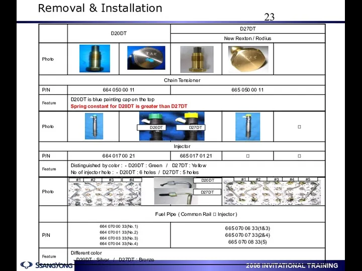
- 24. D20DT D27DT D20DT D27DT #1 #2 #3 #4 #1 #2 #3 #4 #5 Removal & Installation
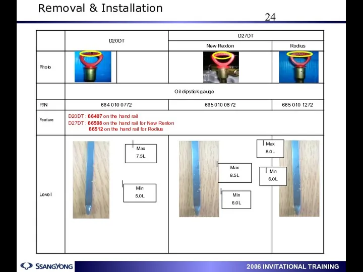
- 25. Max 7.5L Min 5.0L Max 8.5L Min 6.0L Max 8.0L Min 6.0L 7 Removal & Installation
- 26. 1. Types of Turbo Charger Turbo Charger (VGT)
- 27. 2. VGT Principle (Variable Geometry Turbocharger) Engine Speed, RPM 1000 4500 VGT Turbo WGT Turbo Power
- 28. This represents that how much the ECU opens and closes the VGT vacuum modulator, Duty value
- 29. Check if the VGT operates in normal condition by looking into engine rpm/fuel injection amount/boost pressure
- 30. ① Be sure not to transmit external impact on turbo charger to prevent internal damage. 5.
- 31. ④ The screw for adjusting of actuator shaft should not be adjusted, since it’s already adjusted
- 32. 1. ECU Connector Diagnosis
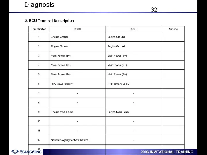
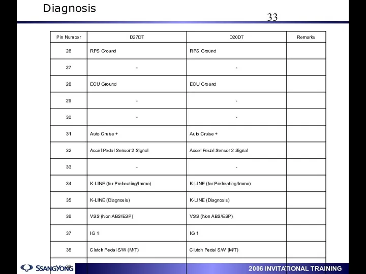
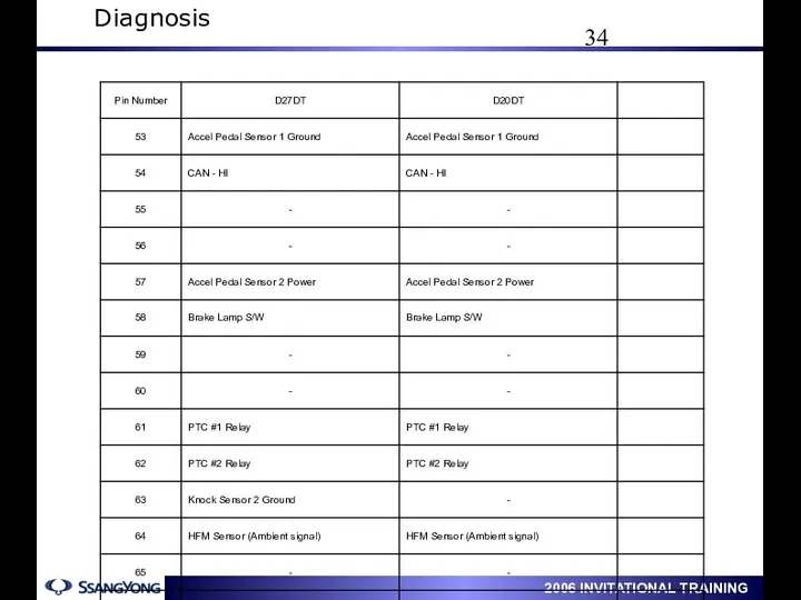
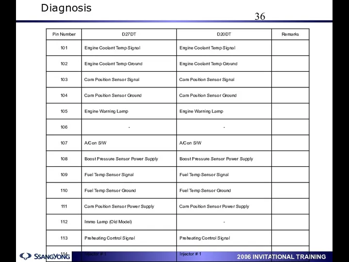
- 33. Diagnosis 2. ECU Terminal Description
- 34. Diagnosis
- 35. Diagnosis
- 36. Diagnosis
- 37. Diagnosis
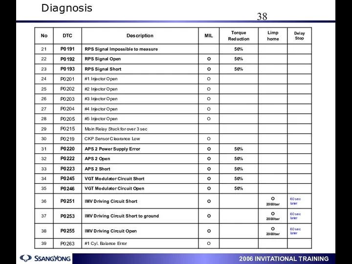
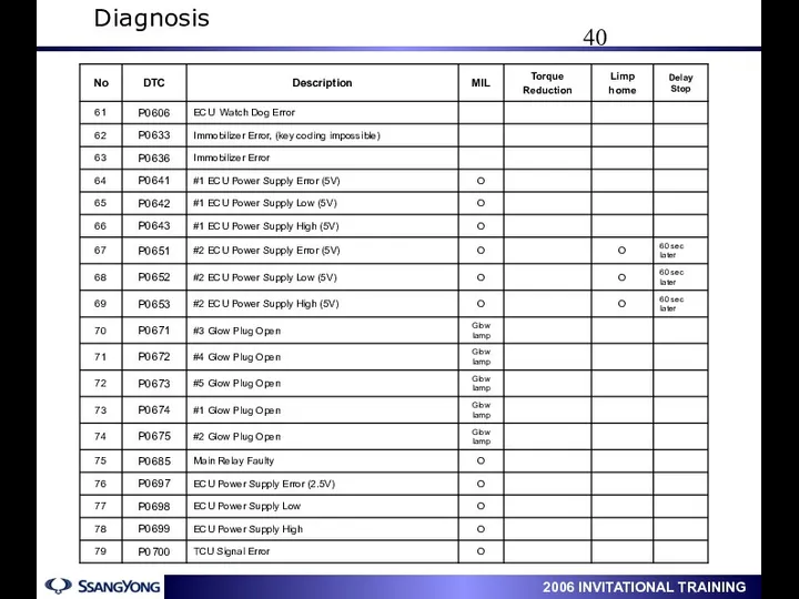
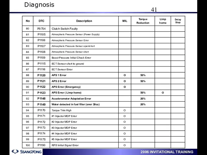
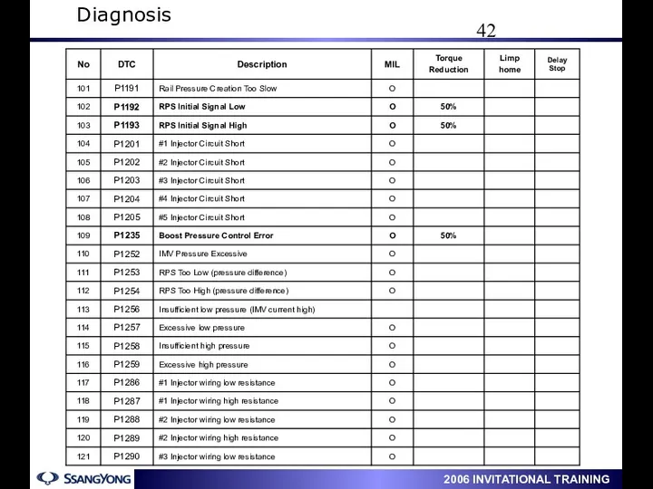
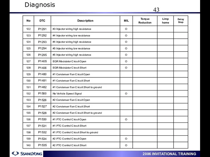
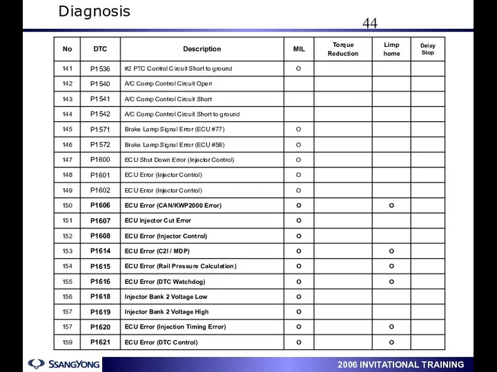
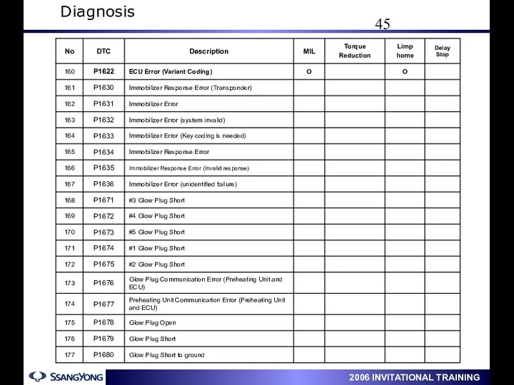
- 38. 2. Diagnostic Trouble Code Diagnosis
- 39. Diagnosis
- 40. Diagnosis
- 41. Diagnosis
- 42. Diagnosis
- 43. Diagnosis
- 44. Diagnosis
- 45. Diagnosis
- 46. Diagnosis
- 47. 3. Electrical Wiring Diagram 1) Preheating Electrical Wiring Diagram
- 48. 2) Power Supply / VGT / EGR / IMV / HFM / APS Electrical Wiring Diagram
- 49. 3) Immobilizer & Sensors Electrical Wiring Diagram
- 50. 4) Injector / Air-con / Triple Pressure Switch Electrical Wiring Diagram
- 51. Data List Analysis Boost Pressure at Stall Test Boost Pressure at Idle 레일 압력 현재값과 목표값(MAP)을
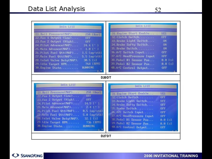
- 52. Data List Analysis
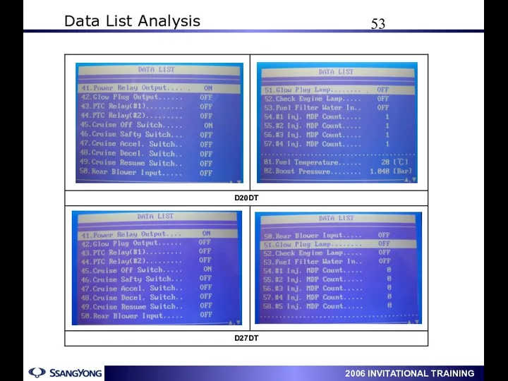
- 53. Data List Analysis
- 54. Data List Analysis
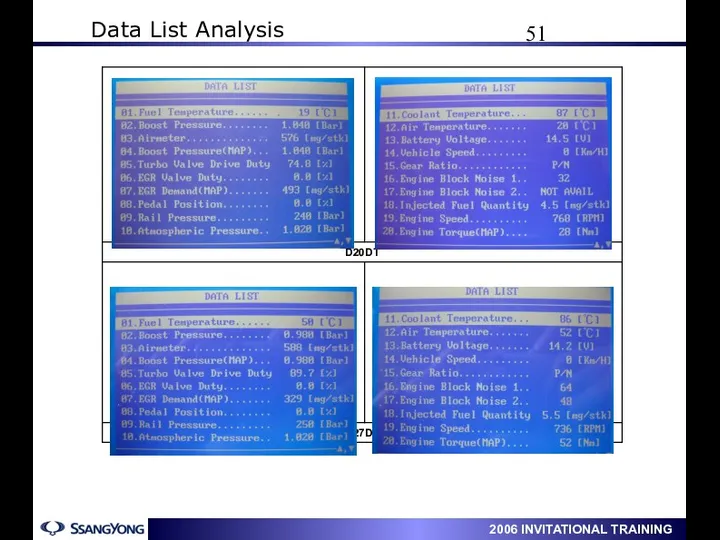
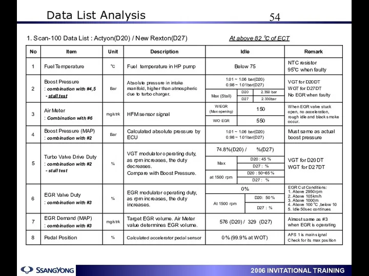
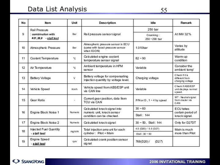
- 55. 1. Scan-100 Data List : Actyon(D20) / New Rexton(D27) At above 82 ℃ of ECT Data
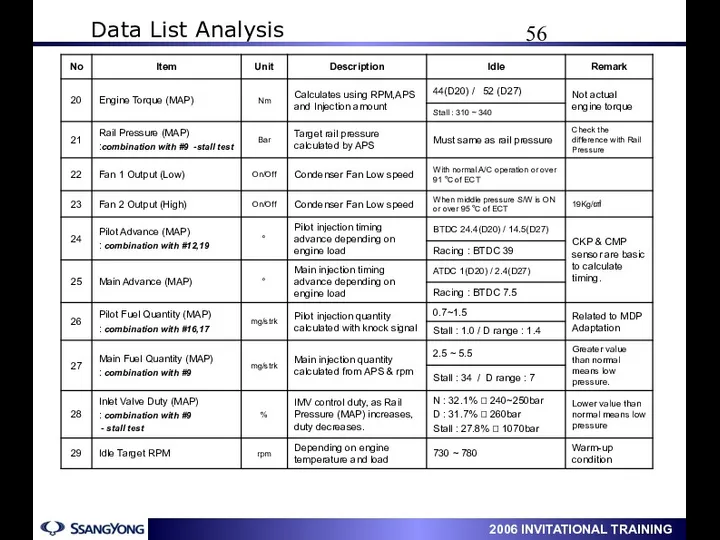
- 56. Data List Analysis
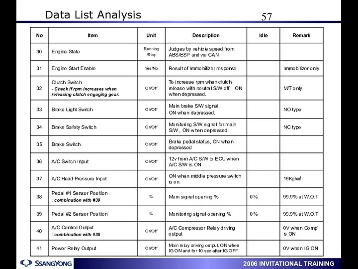
- 57. Data List Analysis
- 58. Data List Analysis
- 60. Скачать презентацию
Contents
D20DT Engine General
Removal & Installation
Turbo Charger (VGT)
Contents
D20DT Engine General
Removal & Installation
Turbo Charger (VGT)
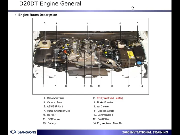
1. Engine Room Description
1. Reservoir Tank 2. FFH(Fuel Fired Heater)
1. Engine Room Description
1. Reservoir Tank 2. FFH(Fuel Fired Heater)
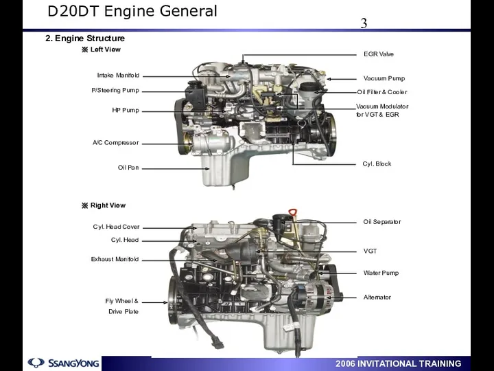
2. Engine Structure
D20DT Engine General
2. Engine Structure
D20DT Engine General
D20DT Engine General
D20DT Engine General
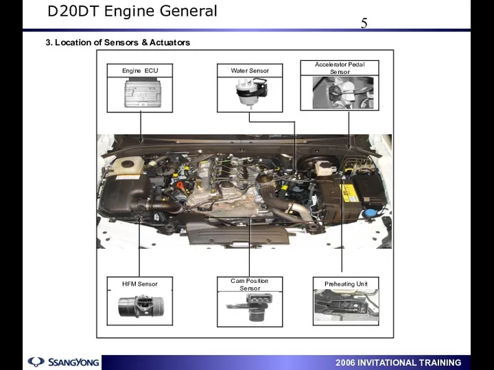
3. Location of Sensors & Actuators
D20DT Engine General
3. Location of Sensors & Actuators
D20DT Engine General

D20DT Engine General
D20DT Engine General
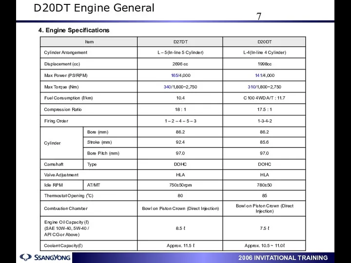
4. Engine Specifications
D20DT Engine General
4. Engine Specifications
D20DT Engine General
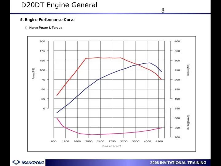
5. Engine Performance Curve
1) Horse Power & Torque
D20DT Engine
5. Engine Performance Curve
1) Horse Power & Torque
D20DT Engine
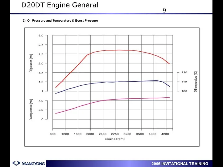
2) Oil Pressure and Temperature & Boost Pressure
D20DT Engine General
2) Oil Pressure and Temperature & Boost Pressure
D20DT Engine General
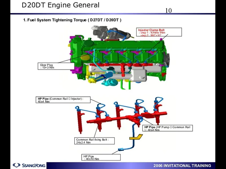
1. Fuel System Tightening Torque ( D27DT / D20DT )
D20DT
1. Fuel System Tightening Torque ( D27DT / D20DT )
D20DT
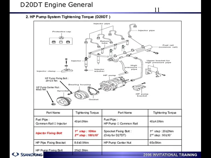
2. HP Pump System Tightening Torque (D20DT )
D20DT Engine General
2. HP Pump System Tightening Torque (D20DT )
D20DT Engine General
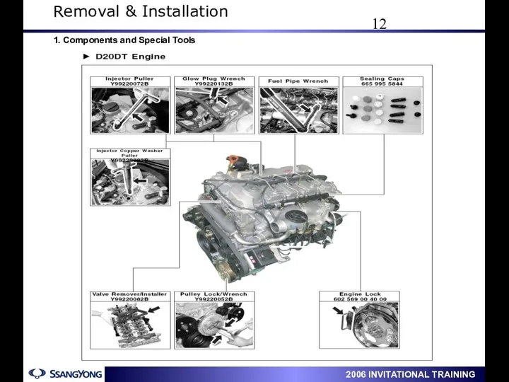
1. Components and Special Tools
Removal & Installation
1. Components and Special Tools
Removal & Installation
Removal & Installation
Removal & Installation
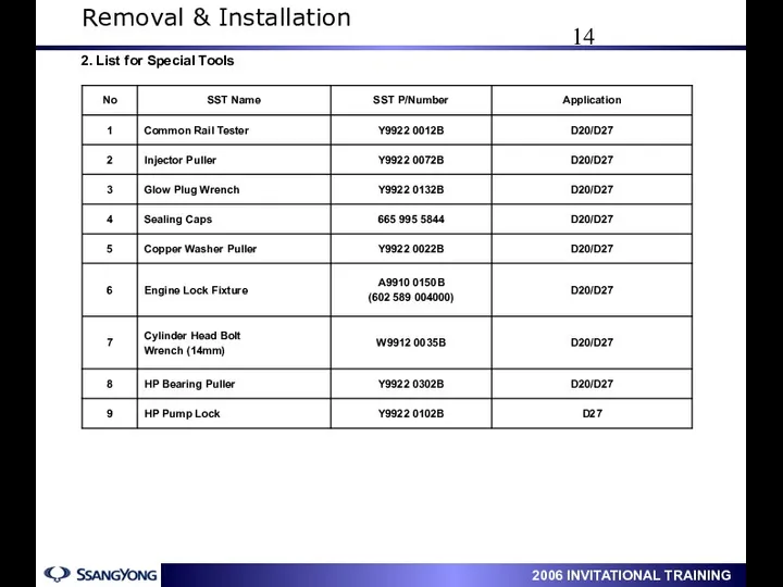
2. List for Special Tools
Removal & Installation
2. List for Special Tools
Removal & Installation
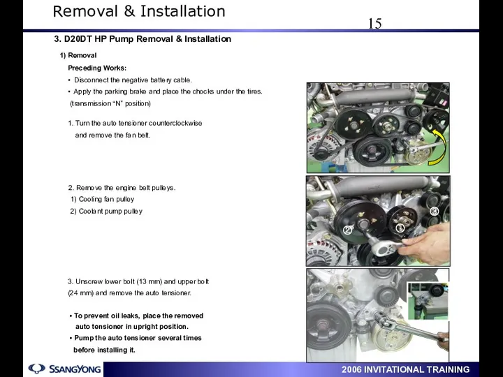
1. Turn the auto tensioner counterclockwise
and remove the fan
1. Turn the auto tensioner counterclockwise
and remove the fan
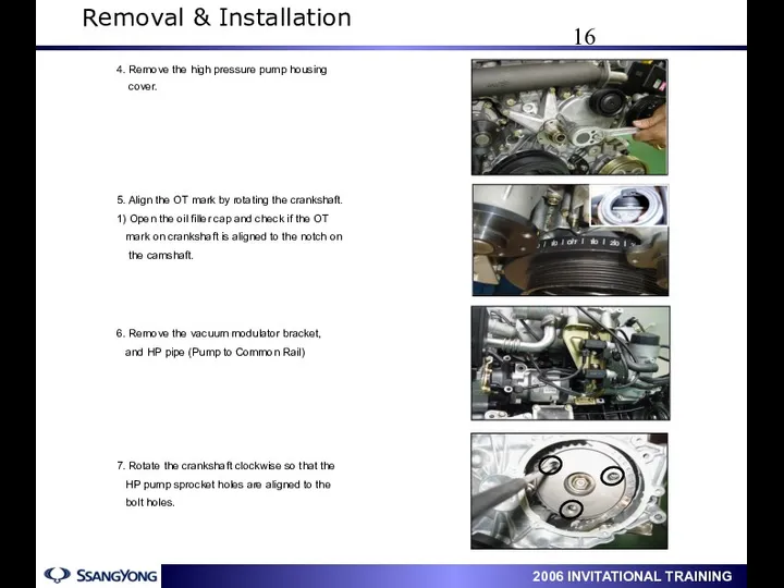
5. Align the OT mark by rotating the crankshaft.
1) Open the
5. Align the OT mark by rotating the crankshaft.
1) Open the
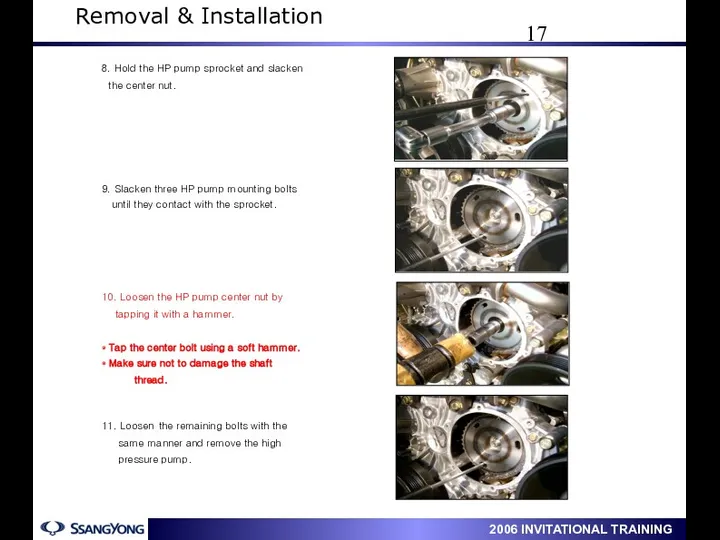
9. Slacken three HP pump mounting bolts
until they contact
9. Slacken three HP pump mounting bolts
until they contact
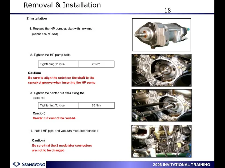
2. Tighten the HP pump bolts.
3. Tighten the center nut after
2. Tighten the HP pump bolts.
3. Tighten the center nut after
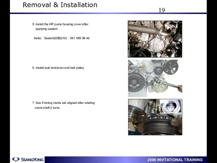
6. Install auto tensioner and belt pulley.
7. See if timing marks
6. Install auto tensioner and belt pulley.
7. See if timing marks
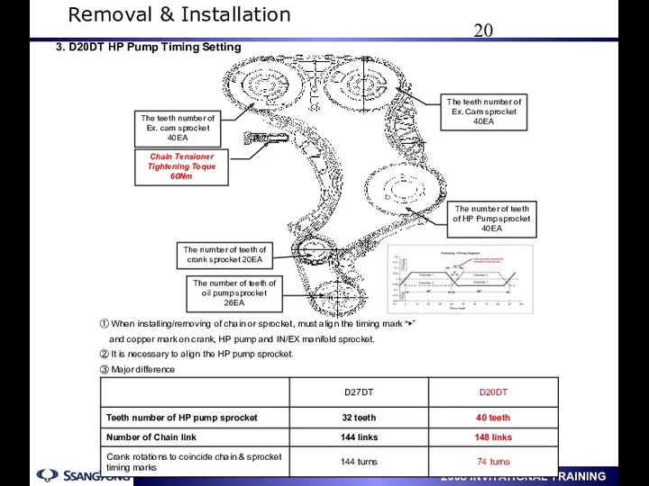
① When installing/removing of chain or sprocket, must align the timing
① When installing/removing of chain or sprocket, must align the timing
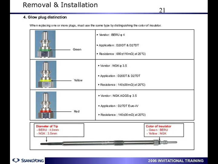
4. Glow plug distinction
When replacing one or more plugs, must use
4. Glow plug distinction
When replacing one or more plugs, must use
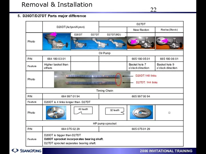
5. D20DT/D27DT Parts major difference
Removal & Installation
5. D20DT/D27DT Parts major difference
Removal & Installation
D20DT
D27DT
D20DT
D27DT
#1
#2
#3
#4
#1
#2
#3
#4
#5
Removal & Installation
D20DT
D27DT
D20DT
D27DT
#1
#2
#3
#4
#1
#2
#3
#4
#5
Removal & Installation
Max
7.5L
Min
5.0L
Max
8.5L
Min
6.0L
Max
8.0L
Min
6.0L
7
Removal & Installation
Max
7.5L
Min
5.0L
Max
8.5L
Min
6.0L
Max
8.0L
Min
6.0L
7
Removal & Installation
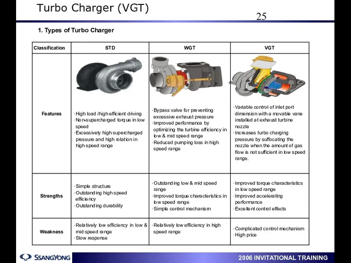
1. Types of Turbo Charger
Turbo Charger (VGT)
1. Types of Turbo Charger
Turbo Charger (VGT)
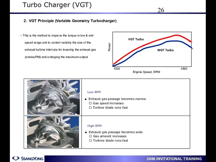
2. VGT Principle (Variable Geometry Turbocharger)
Engine Speed, RPM
1000
4500
VGT Turbo
WGT Turbo
Power
▷
2. VGT Principle (Variable Geometry Turbocharger)
Engine Speed, RPM
1000
4500
VGT Turbo
WGT Turbo
Power
▷
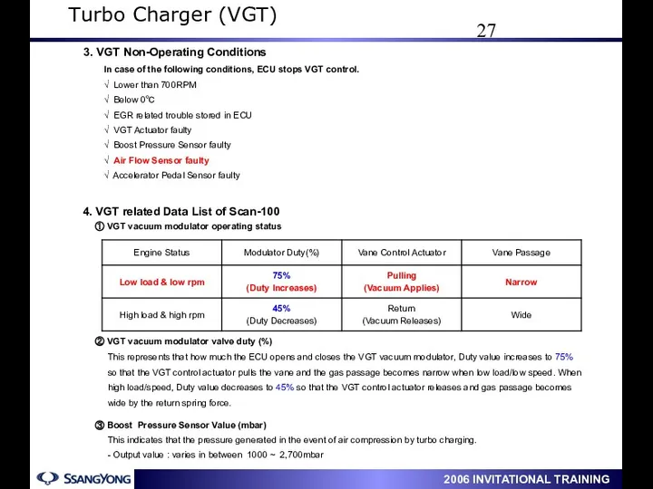
This represents that how much the ECU opens and closes the
This represents that how much the ECU opens and closes the
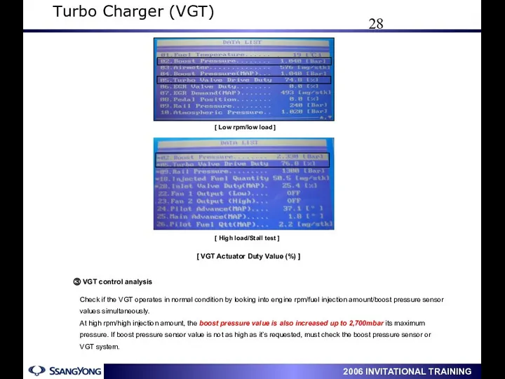
Check if the VGT operates in normal condition by looking into
Check if the VGT operates in normal condition by looking into
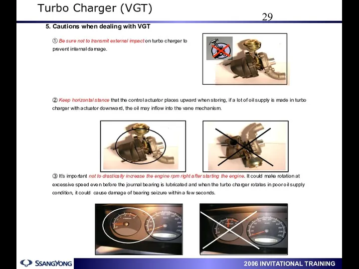
① Be sure not to transmit external impact on turbo charger
① Be sure not to transmit external impact on turbo charger
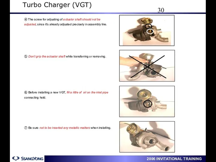
④ The screw for adjusting of actuator shaft should not be
④ The screw for adjusting of actuator shaft should not be
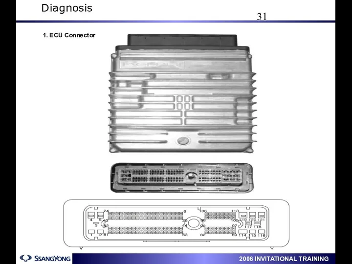
1. ECU Connector
Diagnosis
1. ECU Connector
Diagnosis
Diagnosis
2. ECU Terminal Description
Diagnosis
2. ECU Terminal Description
Diagnosis
Diagnosis
Diagnosis
Diagnosis

Diagnosis
Diagnosis
Diagnosis
Diagnosis
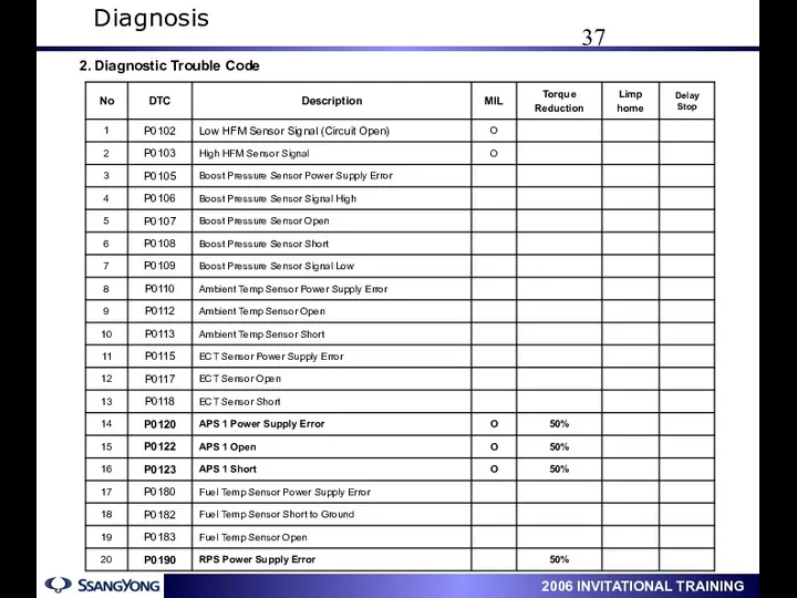
2. Diagnostic Trouble Code
Diagnosis
2. Diagnostic Trouble Code
Diagnosis
Diagnosis
Diagnosis

Diagnosis
Diagnosis
Diagnosis
Diagnosis
Diagnosis
Diagnosis
Diagnosis
Diagnosis
Diagnosis
Diagnosis
Diagnosis
Diagnosis
Diagnosis
Diagnosis
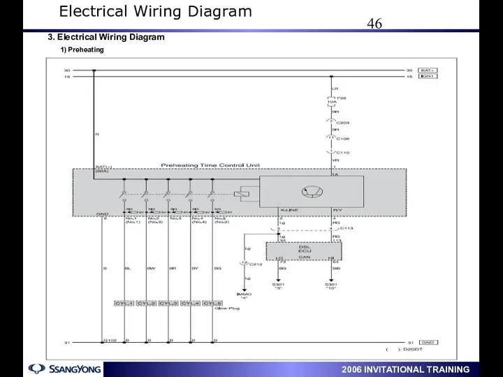
3. Electrical Wiring Diagram
1) Preheating
Electrical Wiring Diagram
3. Electrical Wiring Diagram
1) Preheating
Electrical Wiring Diagram
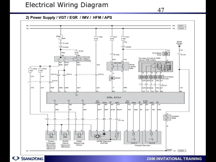
2) Power Supply / VGT / EGR / IMV / HFM
2) Power Supply / VGT / EGR / IMV / HFM
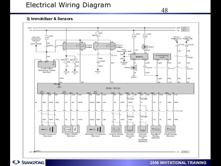
3) Immobilizer & Sensors
Electrical Wiring Diagram
3) Immobilizer & Sensors
Electrical Wiring Diagram
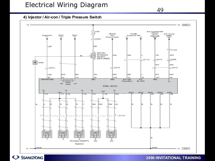
4) Injector / Air-con / Triple Pressure Switch
Electrical Wiring Diagram
4) Injector / Air-con / Triple Pressure Switch
Electrical Wiring Diagram
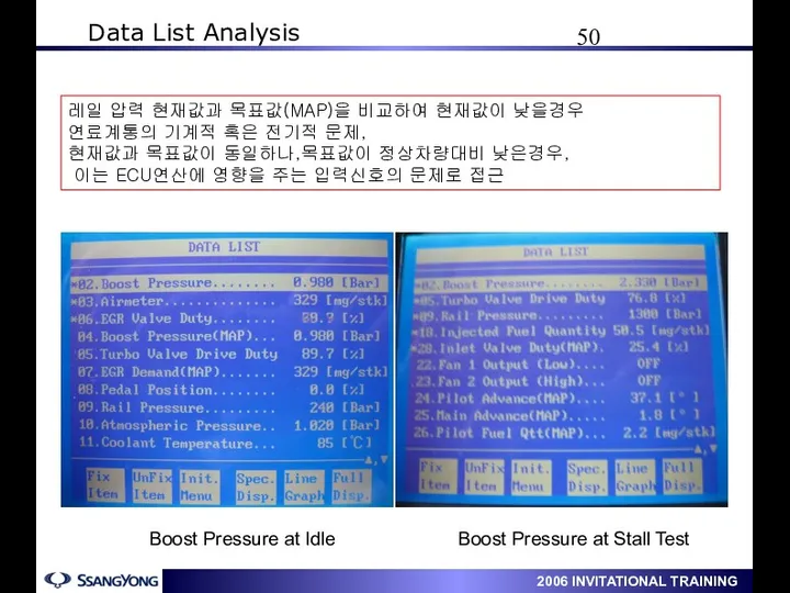
Data List Analysis
Boost Pressure at Stall Test
Boost Pressure
Data List Analysis
Boost Pressure at Stall Test
Boost Pressure
Data List Analysis
Data List Analysis
Data List Analysis
Data List Analysis
Data List Analysis
Data List Analysis
1. Scan-100 Data List : Actyon(D20) / New Rexton(D27) At above
1. Scan-100 Data List : Actyon(D20) / New Rexton(D27) At above
Data List Analysis
Data List Analysis
Data List Analysis
Data List Analysis
Data List Analysis
Data List Analysis
 Снаряжение первоклассника (презентация)
 координатная прямая
 Экологические болезни
 Литература 1950-1980 гг
 Полуфабрикаты из мяса говядины
 Спряжение глаголов (урок русского языка в 4 классе)
 Установка гнб. Применение современных технологий в ланшафтном строительстве
 Болезнь Такаясу (неспецифический аортоартериит)
 Цифровая схемотехника. Счетчики. (Лекция 11)
 Глобальная сеть Интернет
 Портфолио учащегося
 Чудо - дерево. Сказки и оформление детей подготовительной группы № 9
 Особенности устройства рельсовой колеи на кривом участке двухпутной линии
 День Победы (2). Фото
 Что изучает история
 Технология коллективного творческого воспитания
 Кафе-пиццерия Coffecup
 Основные технико-экономические показатели ТЭС; методы разделения производимой энергии
 Основные понятия о грузах
 Категория птицы. Категория животные
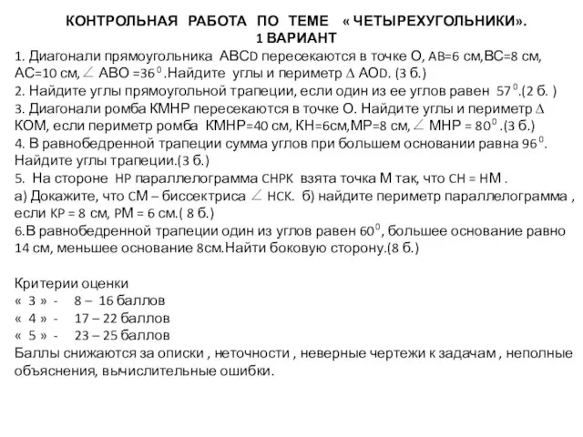 Контрольная работа по теме Четырехугольники
 Английские надписи на одежде и их влияние на культуру современных подростков
 Способы ориентирования. 6 класс
 Презентация Использование метода наглядного моделирования в работе логопеда
 Технические средства наноэлектроники. Методы получения тонких пленок. (Тема 3.2)
 Крылатые слова
 Логистическая оптимизация материального потока в сфере обращения
 Программа расчета на прочность и устойчивость сосудов и аппаратов для оценки несущей способности при рабочих условиях