- agc150 training basic v1

Содержание
- 2. Synchronizing Controllers GPC-3 Base mounted Non-Power Management AGC 200 Front mounted Standard Power Management AGC-4 Base
- 3. Documentation www.deif.com contains all manuals for the controllers
- 4. Documentation
- 5. AGC 150
- 6. AGC 150 RS485 (1)
- 7. Typical wiring
- 8. Setup Current Transformer Basic Settings Configurable CT
- 9. Nominal settings Basic Settings Configurable CT
- 10. Start Sequence 1. Before starting, start prepare ON (Relay 9). Can be used to activate pre-heating
- 11. Generator Protection Checkmark [ √ ] = enable And many more protections…
- 12. Generator Protection Fail class: Trip + stop = GB trip, engine stop after cooling down Safety
- 13. I/O DIGITAL INPUT DIGITAL OUTPUT ANALOG INPUT
- 14. Digital Input 12 digital inputs, activated by negative (-) VDC signal Each can be configured as:
- 15. Digital Input 1. Digital input as alarm Parameter > I/O settings > Inputs > Digital inputs
- 16. Digital Input 2. Digital input as Function Click icon I/O settings Configuration input/output settings
- 17. Digital Input Default assignment
- 18. Digital Output 12 digital outputs (DC outputs) Require common positive (+) VDC Configuration by USW
- 19. Digital Output Setup digital output Click icon I/O settings Configuration input/output settings
- 20. Digital output Default assignment:
- 21. Analog Input 4 multi inputs Selectable for: - 4-20 mA - RMI Oil Pressure - 0-10
- 22. Analog Input Configuring multi inputs
- 23. Input & Output Text To change text, use Translations
- 24. Input & Output Status Any digital input/output can be monitored trough USW and display
- 25. Analog Regulation SPEED REGULATION - ANALOG VOLTAGE REGULATION - ANALOG
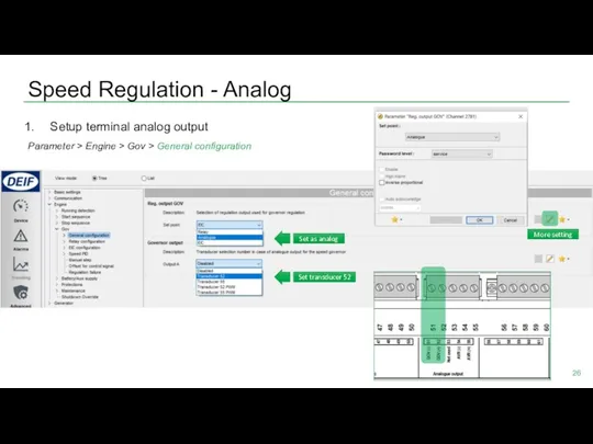
- 26. Speed Regulation - Analog Setup terminal analog output Parameter > Engine > Gov > General configuration
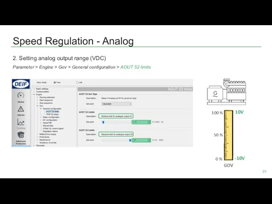
- 27. Speed Regulation - Analog 2. Setting analog output range (VDC) Parameter > Engine > Gov >
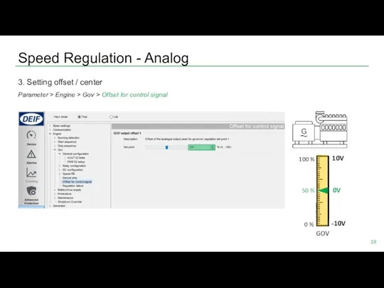
- 28. Speed Regulation - Analog 3. Setting offset / center Parameter > Engine > Gov > Offset
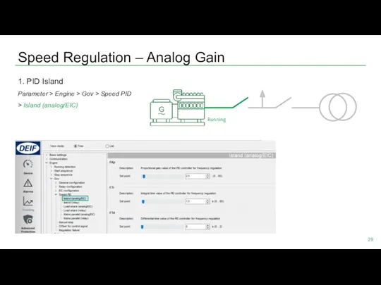
- 29. Speed Regulation – Analog Gain 1. PID Island Parameter > Engine > Gov > Speed PID
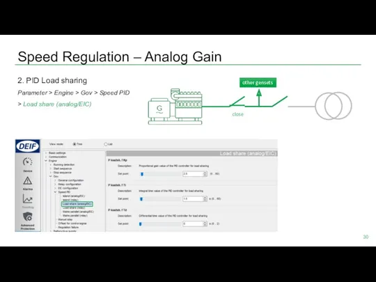
- 30. Speed Regulation – Analog Gain 2. PID Load sharing Parameter > Engine > Gov > Speed
- 31. Speed Regulation – Analog Gain 3. PID Mains parallel Parameter > Engine > Gov > Speed
- 32. Voltage Regulation - Analog Setup terminal analog output Parameter > Generator > AVR > General configuration
- 33. Voltage Regulation - Analog 2. Setting analog output range & center Parameter > Generator > AVR
- 34. Voltage Regulation – Analog Gain Same principle with speed PID Parameter > Generator > AVR >
- 35. Analog Regulation Status Check Device > Governor reg. > AVR reg.
- 36. Relay regulation SPEED REGULATION - RELAY VOLTAGE REGULATION - RELAY
- 37. Speed Regulation - Relay 1. Change Gov setting to relay Parameter > Engine > Gov >
- 38. Speed Regulation - Relay 2. Setup pulse signal and choosing relay terminals Parameter > Engine >
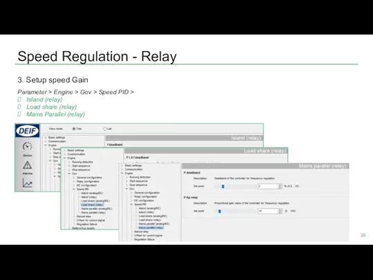
- 39. Speed Regulation - Relay 3. Setup speed Gain Parameter > Engine > Gov > Speed PID
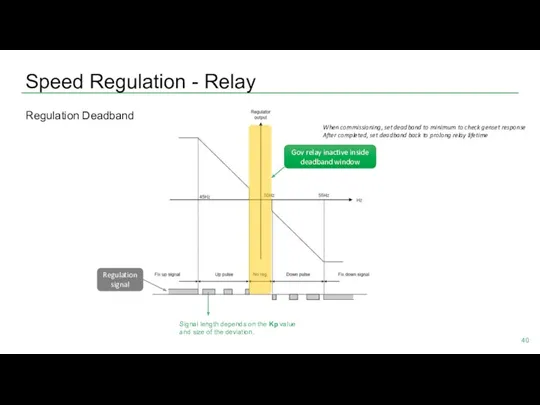
- 40. Speed Regulation - Relay Regulation Deadband Signal length depends on the Kp value and size of
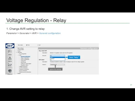
- 41. Voltage Regulation - Relay 1. Change AVR setting to relay Parameter > Generator > AVR >
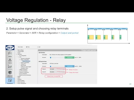
- 42. Voltage Regulation - Relay 2. Setup pulse signal and choosing relay terminals Parameter > Generator >
- 43. Voltage Regulation - Relay 3. Setup voltage Gain Parameter > Generator > AVR > Voltage PID
- 44. Relay Regulation Status Check Device > Governor reg. > AVR reg.
- 45. Synchronisation
- 46. Synchronisation AGC always perform synchronism check before closing breakers All modes: Auto, Semi Auto, and Manual
- 47. Synchronisation Change slip frequency & voltage Synchronisation > Dynamic synchronisation Slip Frequency Slip Voltage Here, to
- 48. Application SINGLE GENSET MULTIPLE GENSETS
- 49. Adapting Mimic Standalone AMF Genset BTB MAINS MAINS+TB Standalone Parallel without MB Standalone Island
- 50. Typical Applications for AGC 150 Single Genset Single Genset with Mains Multiple Genset’s with Mains Genset
- 51. Application SINGLE GENSET
- 52. Single Genset Application configuration New plant configuration “Single DG” Mains Single Genset with Mains
- 53. Single Genset Alternative setup:* Access from AGC 150 display: Settings > Basic settings > Application type
- 54. Single Genset Select Genset Mode Parameter > Basic settings > Application type > Genset type >
- 55. Single Genset Enable Back Synchronising Parameter > Synchronisation > Mains parallel settings
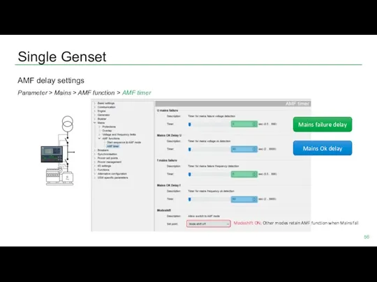
- 56. Single Genset AMF delay settings Parameter > Mains > AMF function > AMF timer Modeshift ON:
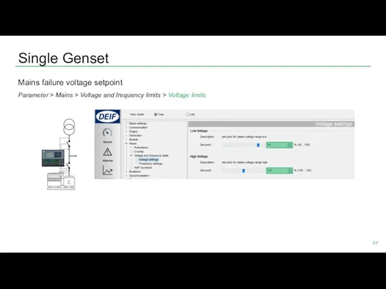
- 57. Single Genset Mains failure voltage setpoint Parameter > Mains > Voltage and frequency limits > Voltage
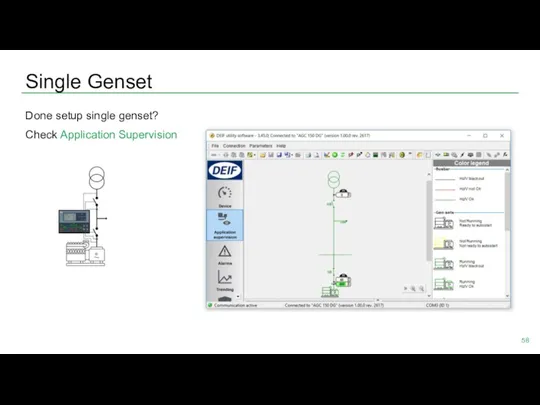
- 58. Single Genset Done setup single genset? Check Application Supervision
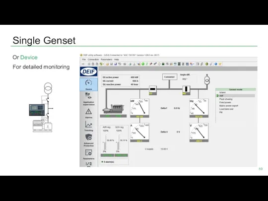
- 59. Single Genset Or Device For detailed monitoring
- 60. Application MULTIPLE GENSETS
- 61. Multiple Gensets ? Application configuration ? New plant configuration Genset 1 Genset 2 “Standard” Create drawing
- 62. Multiple Gensets Select Genset Mode Parameter > Basic settings > Application type > Genset type >
- 63. Multiple Gensets Setup ID Number Parameter > Communication > Power management ID Genset 1 Genset 2
- 64. Multiple Gensets CANbus wiring Genset 1 Genset 2 put resistor 120 Ω on both ends CAN
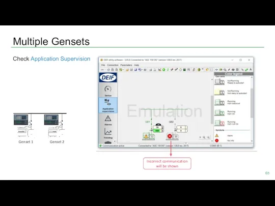
- 65. Multiple Gensets Check Application Supervision Incorrect communication will be shown Genset 1 Genset 2
- 66. Power Management LOAD DEPENDENT START/STOP MULTI START Genset 1 Genset 2
- 67. Load dependent start/stop Configure Start/stop based on load Percentage Parameter > Power management > Load dependent
- 68. Load dependent start/stop Start percentage setpoint Parameter > Power management > Load dependent start 1 Genset
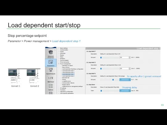
- 69. Load dependent start/stop Stop percentage setpoint Parameter > Power management > Load dependent stop 1 Genset
- 70. Multi start Setup of how many gensets start together Parameter > Power management > Multi start
- 73. Скачать презентацию
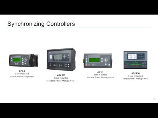
Synchronizing Controllers
GPC-3
Base mounted
Non-Power Management
AGC 200
Front mounted
Standard Power Management
AGC-4
Base mounted
Custom Power Management
AGC
Synchronizing Controllers
GPC-3
Base mounted
Non-Power Management
AGC 200
Front mounted
Standard Power Management
AGC-4
Base mounted
Custom Power Management
AGC
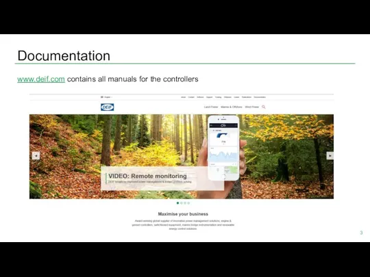
Documentation
www.deif.com contains all manuals for the controllers
Documentation
www.deif.com contains all manuals for the controllers
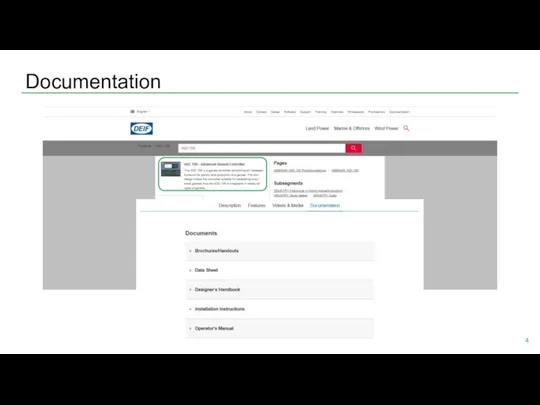
Documentation
Documentation
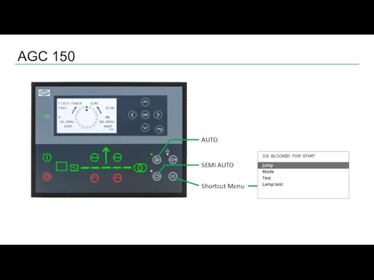
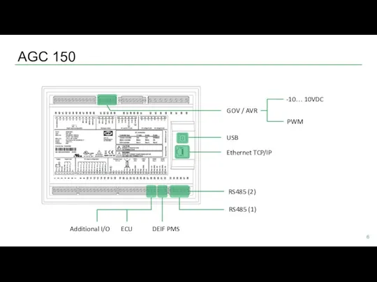
AGC 150
AGC 150
AGC 150
RS485 (1)
AGC 150
RS485 (1)
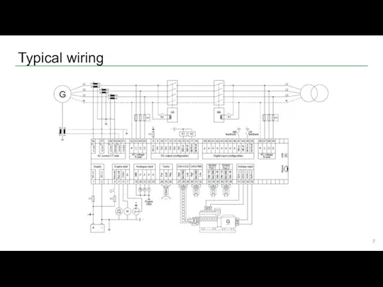
Typical wiring
Typical wiring
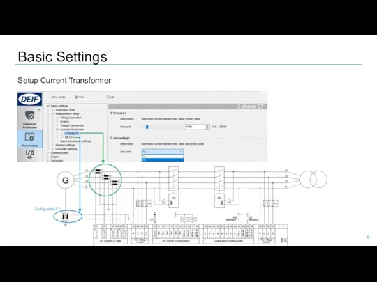
Setup Current Transformer
Basic Settings
Configurable CT
Setup Current Transformer
Basic Settings
Configurable CT
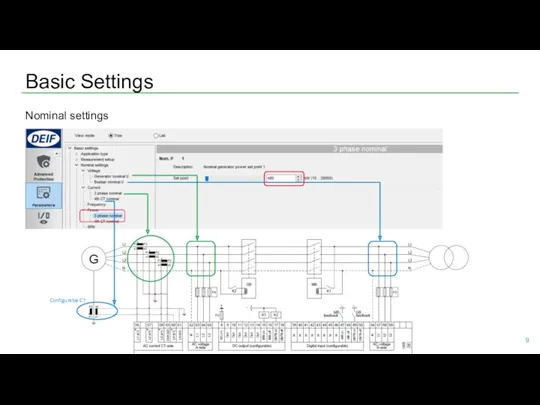
Nominal settings
Basic Settings
Configurable CT
Nominal settings
Basic Settings
Configurable CT
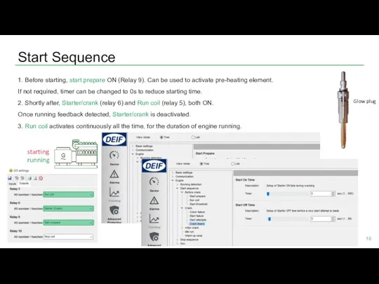
Start Sequence
1. Before starting, start prepare ON (Relay 9). Can be
Start Sequence
1. Before starting, start prepare ON (Relay 9). Can be
![Generator Protection Checkmark [ √ ] = enable And many more protections…](/_ipx/f_webp&q_80&fit_contain&s_1440x1080/imagesDir/jpg/1361/slide-10.jpg)
Generator Protection
Checkmark [ √ ] = enable
And many more protections…
Generator Protection
Checkmark [ √ ] = enable
And many more protections…
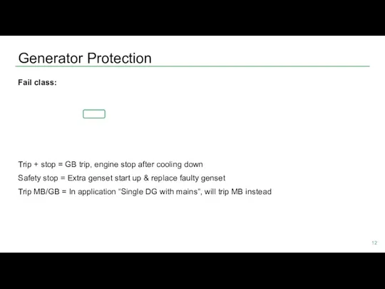
Generator Protection
Fail class:
Trip + stop = GB trip, engine stop after
Generator Protection
Fail class:
Trip + stop = GB trip, engine stop after
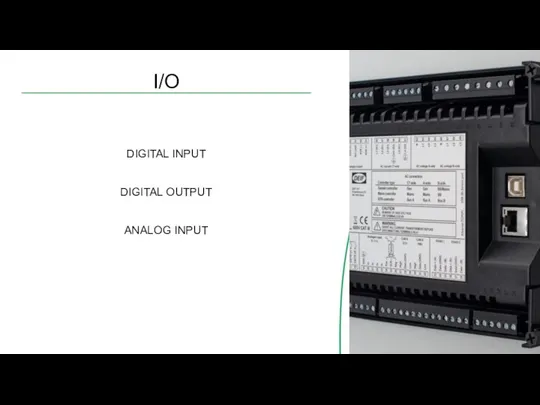
I/O
DIGITAL INPUT
DIGITAL OUTPUT
ANALOG INPUT
I/O
DIGITAL INPUT
DIGITAL OUTPUT
ANALOG INPUT
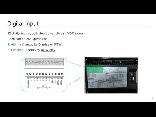
Digital Input
12 digital inputs, activated by negative (-) VDC signal
Each
Digital Input
12 digital inputs, activated by negative (-) VDC signal
Each
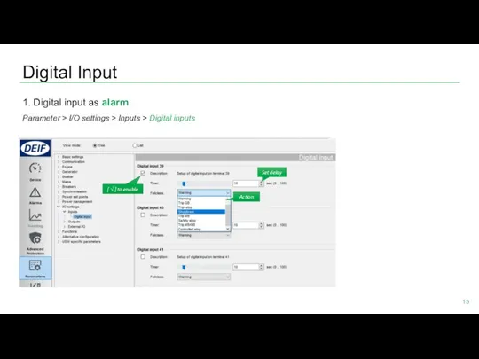
Digital Input
1. Digital input as alarm
Parameter > I/O settings > Inputs
Digital Input
1. Digital input as alarm
Parameter > I/O settings > Inputs
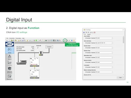
Digital Input
2. Digital input as Function
Click icon I/O settings
Configuration input/output settings
Digital Input
2. Digital input as Function
Click icon I/O settings
Configuration input/output settings
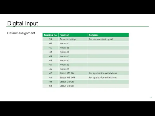
Digital Input
Default assignment
Digital Input
Default assignment
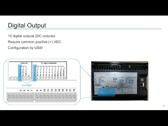
Digital Output
12 digital outputs (DC outputs)
Require common positive (+) VDC
Configuration by
Digital Output
12 digital outputs (DC outputs)
Require common positive (+) VDC
Configuration by
Digital Output
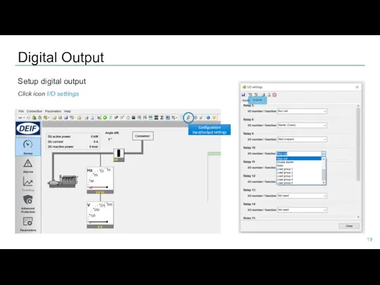
Setup digital output
Click icon I/O settings
Configuration input/output settings
Digital Output
Setup digital output
Click icon I/O settings
Configuration input/output settings
Digital output
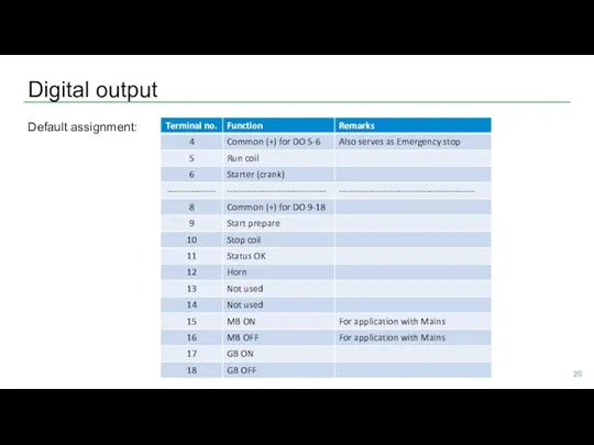
Default assignment:
Digital output
Default assignment:
Analog Input
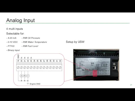
4 multi inputs
Selectable for:
- 4-20 mA - RMI Oil Pressure
- 0-10
Analog Input
4 multi inputs
Selectable for:
- 4-20 mA - RMI Oil Pressure
- 0-10
Analog Input
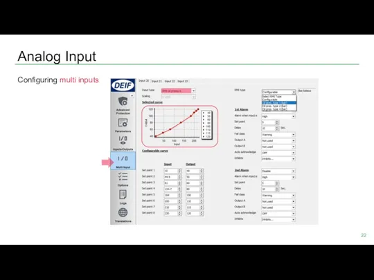
Configuring multi inputs
Analog Input
Configuring multi inputs
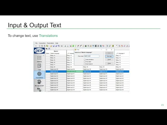
Input & Output Text
To change text, use Translations
Input & Output Text
To change text, use Translations
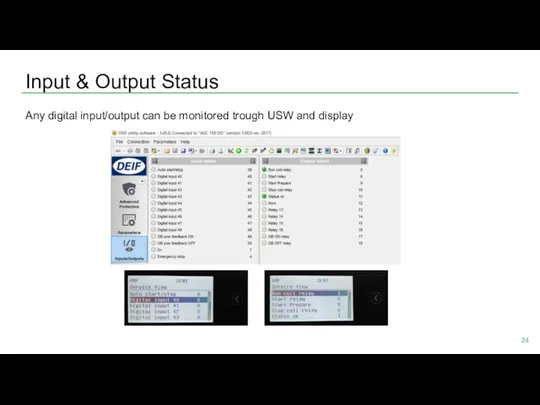
Input & Output Status
Any digital input/output can be monitored trough USW
Input & Output Status
Any digital input/output can be monitored trough USW
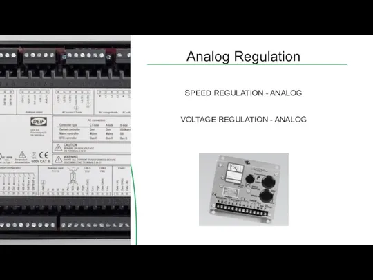
Analog Regulation
SPEED REGULATION - ANALOG
VOLTAGE REGULATION - ANALOG
Analog Regulation
SPEED REGULATION - ANALOG
VOLTAGE REGULATION - ANALOG
Speed Regulation - Analog
Setup terminal analog output
Parameter > Engine > Gov
Speed Regulation - Analog
Setup terminal analog output
Parameter > Engine > Gov
Speed Regulation - Analog
2. Setting analog output range (VDC)
Parameter > Engine
Speed Regulation - Analog
2. Setting analog output range (VDC)
Parameter > Engine
Speed Regulation - Analog
3. Setting offset / center
Parameter > Engine >
Speed Regulation - Analog
3. Setting offset / center
Parameter > Engine >
Speed Regulation – Analog Gain
1. PID Island
Parameter > Engine > Gov
Speed Regulation – Analog Gain
1. PID Island
Parameter > Engine > Gov
Speed Regulation – Analog Gain
2. PID Load sharing
Parameter > Engine >
Speed Regulation – Analog Gain
2. PID Load sharing
Parameter > Engine >
Speed Regulation – Analog Gain
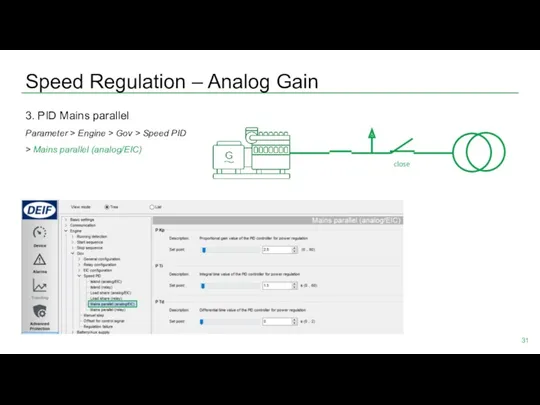
3. PID Mains parallel
Parameter > Engine >
Speed Regulation – Analog Gain
3. PID Mains parallel
Parameter > Engine >
Voltage Regulation - Analog
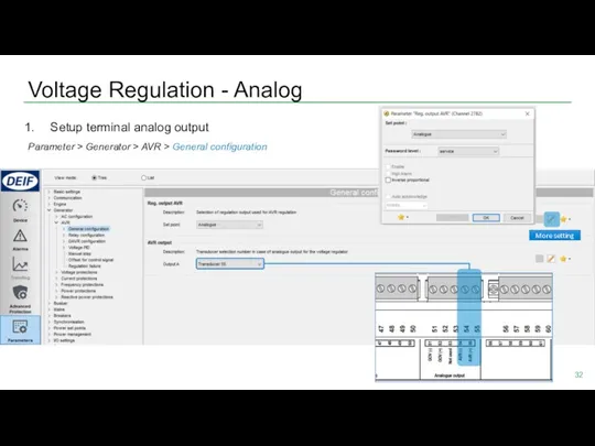
Setup terminal analog output
Parameter > Generator > AVR
Voltage Regulation - Analog
Setup terminal analog output
Parameter > Generator > AVR
Voltage Regulation - Analog
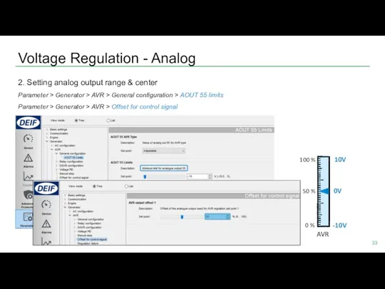
2. Setting analog output range & center
Parameter
Voltage Regulation - Analog
2. Setting analog output range & center
Parameter
Voltage Regulation – Analog Gain
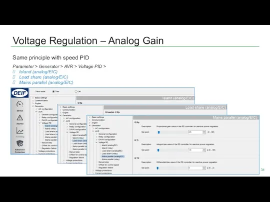
Same principle with speed PID
Parameter > Generator
Voltage Regulation – Analog Gain
Same principle with speed PID
Parameter > Generator
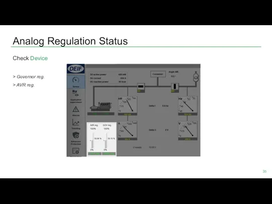
Analog Regulation Status
Check Device
> Governor reg.
> AVR reg.
Analog Regulation Status
Check Device
> Governor reg.
> AVR reg.
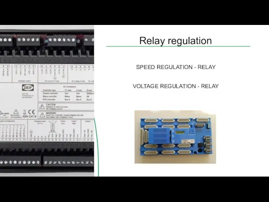
Relay regulation
SPEED REGULATION - RELAY
VOLTAGE REGULATION - RELAY
Relay regulation
SPEED REGULATION - RELAY
VOLTAGE REGULATION - RELAY
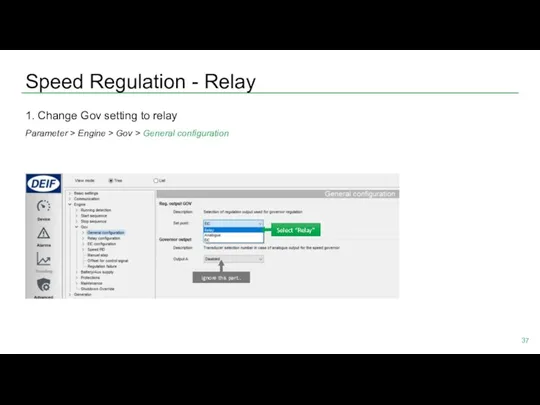
Speed Regulation - Relay
1. Change Gov setting to relay
Parameter > Engine
Speed Regulation - Relay
1. Change Gov setting to relay
Parameter > Engine
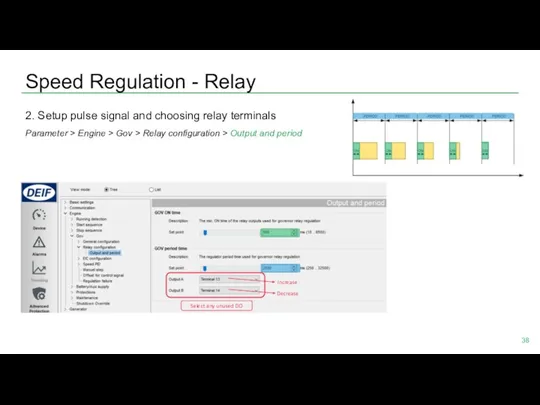
Speed Regulation - Relay
2. Setup pulse signal and choosing relay terminals
Parameter
Speed Regulation - Relay
2. Setup pulse signal and choosing relay terminals
Parameter
Speed Regulation - Relay
3. Setup speed Gain
Parameter > Engine > Gov
Speed Regulation - Relay
3. Setup speed Gain
Parameter > Engine > Gov
Speed Regulation - Relay
Regulation Deadband
Signal length depends on the Kp value
Speed Regulation - Relay
Regulation Deadband
Signal length depends on the Kp value
Voltage Regulation - Relay
1. Change AVR setting to relay
Parameter > Generator
Voltage Regulation - Relay
1. Change AVR setting to relay
Parameter > Generator
Voltage Regulation - Relay
2. Setup pulse signal and choosing relay terminals
Parameter
Voltage Regulation - Relay
2. Setup pulse signal and choosing relay terminals
Parameter
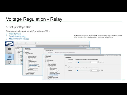
Voltage Regulation - Relay
3. Setup voltage Gain
Parameter > Generator > AVR
Voltage Regulation - Relay
3. Setup voltage Gain
Parameter > Generator > AVR

Relay Regulation Status
Check Device
> Governor reg.
> AVR reg.
Relay Regulation Status
Check Device
> Governor reg.
> AVR reg.
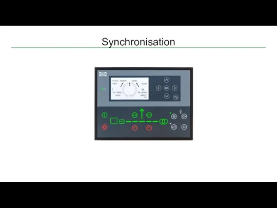
Synchronisation
Synchronisation
Synchronisation
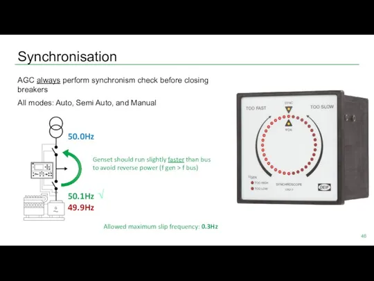
AGC always perform synchronism check before closing breakers
All modes: Auto, Semi
Synchronisation
AGC always perform synchronism check before closing breakers
All modes: Auto, Semi
Synchronisation
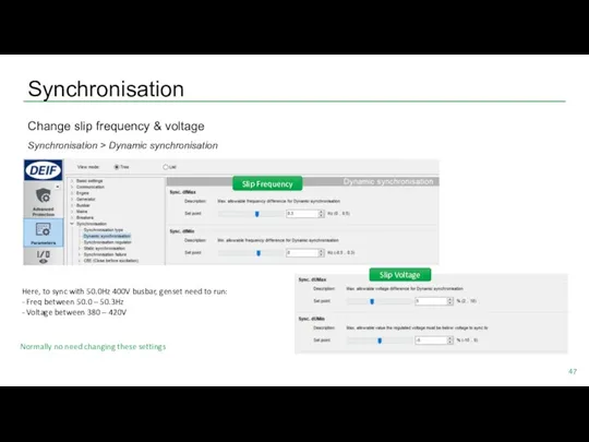
Change slip frequency & voltage
Synchronisation > Dynamic synchronisation
Slip Frequency
Slip Voltage
Here, to
Synchronisation
Change slip frequency & voltage
Synchronisation > Dynamic synchronisation
Slip Frequency
Slip Voltage
Here, to
Application
SINGLE GENSET
MULTIPLE GENSETS
Application
SINGLE GENSET
MULTIPLE GENSETS
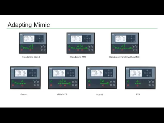
Adapting Mimic
Standalone AMF
Genset
BTB
MAINS
MAINS+TB
Standalone Parallel without MB
Standalone Island
Adapting Mimic
Standalone AMF
Genset
BTB
MAINS
MAINS+TB
Standalone Parallel without MB
Standalone Island
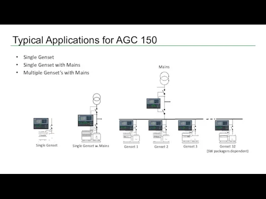
Typical Applications for AGC 150
Single Genset
Single Genset with Mains
Multiple Genset’s with
Typical Applications for AGC 150
Single Genset
Single Genset with Mains
Multiple Genset’s with
Application
SINGLE GENSET
Application
SINGLE GENSET
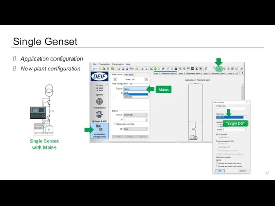
Single Genset
Application configuration
New plant configuration
“Single DG”
Mains
Single Genset
with Mains
Single Genset
Application configuration
New plant configuration
“Single DG”
Mains
Single Genset
with Mains
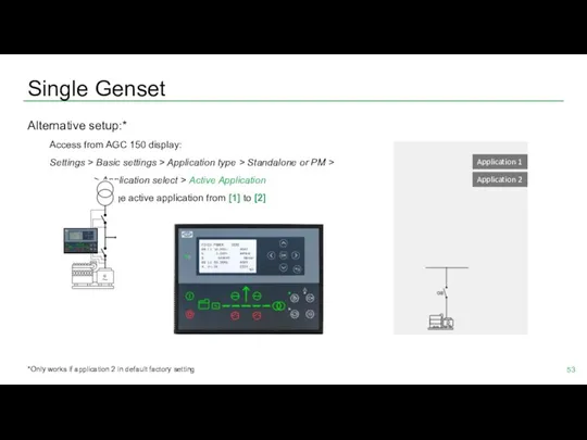
Single Genset
Alternative setup:*
Access from AGC 150 display:
Settings > Basic settings >
Single Genset
Alternative setup:*
Access from AGC 150 display:
Settings > Basic settings >
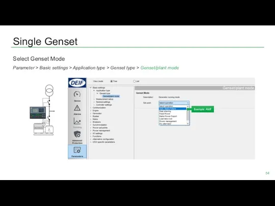
Single Genset
Select Genset Mode
Parameter > Basic settings > Application type >
Single Genset
Select Genset Mode
Parameter > Basic settings > Application type >
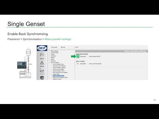
Single Genset
Enable Back Synchronising
Parameter > Synchronisation > Mains parallel settings
Single Genset
Enable Back Synchronising
Parameter > Synchronisation > Mains parallel settings
Single Genset
AMF delay settings
Parameter > Mains > AMF function > AMF
Single Genset
AMF delay settings
Parameter > Mains > AMF function > AMF
Single Genset
Mains failure voltage setpoint
Parameter > Mains > Voltage and frequency
Single Genset
Mains failure voltage setpoint
Parameter > Mains > Voltage and frequency
Single Genset
Done setup single genset?
Check Application Supervision
Single Genset
Done setup single genset?
Check Application Supervision
Single Genset
Or Device
For detailed monitoring
Single Genset
Or Device
For detailed monitoring
Application
MULTIPLE GENSETS
Application
MULTIPLE GENSETS
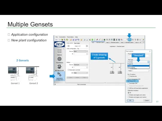
Multiple Gensets
? Application configuration
? New plant configuration
Genset 1
Genset 2
“Standard”
Create drawing
of
Multiple Gensets
? Application configuration
? New plant configuration
Genset 1
Genset 2
“Standard”
Create drawing
of
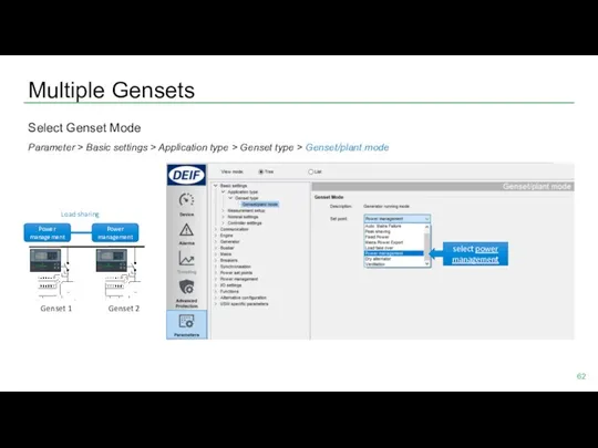
Multiple Gensets
Select Genset Mode
Parameter > Basic settings > Application type >
Multiple Gensets
Select Genset Mode
Parameter > Basic settings > Application type >
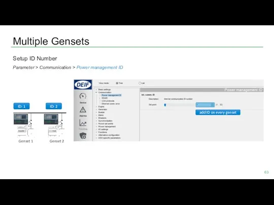
Multiple Gensets
Setup ID Number
Parameter > Communication > Power management ID
Genset 1
Genset
Multiple Gensets
Setup ID Number
Parameter > Communication > Power management ID
Genset 1
Genset

Multiple Gensets
CANbus wiring
Genset 1
Genset 2
put resistor 120 Ω
on both ends
CAN PMS
Multiple Gensets
CANbus wiring
Genset 1
Genset 2
put resistor 120 Ω
on both ends
CAN PMS
Multiple Gensets
Check Application Supervision
Incorrect communication will be shown
Genset 1
Genset 2
Multiple Gensets
Check Application Supervision
Incorrect communication will be shown
Genset 1
Genset 2
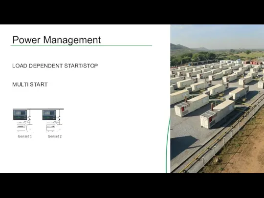
Power Management
LOAD DEPENDENT START/STOP
MULTI START
Genset 1
Genset 2
Power Management
LOAD DEPENDENT START/STOP
MULTI START
Genset 1
Genset 2
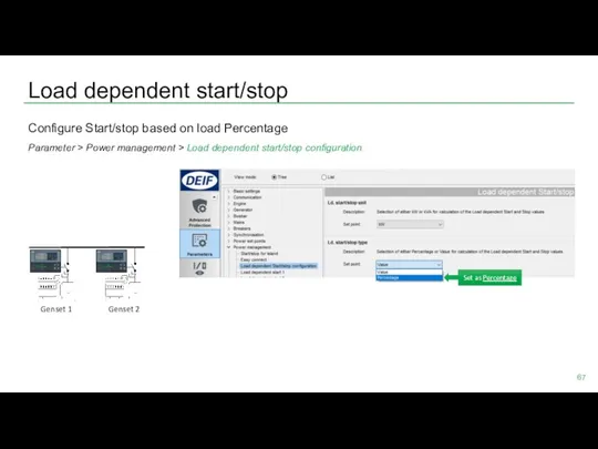
Load dependent start/stop
Configure Start/stop based on load Percentage
Parameter > Power management
Load dependent start/stop
Configure Start/stop based on load Percentage
Parameter > Power management
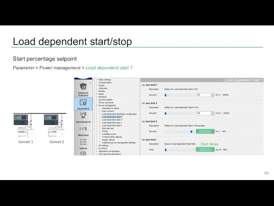
Load dependent start/stop
Start percentage setpoint
Parameter > Power management > Load dependent
Load dependent start/stop
Start percentage setpoint
Parameter > Power management > Load dependent
Load dependent start/stop
Stop percentage setpoint
Parameter > Power management > Load dependent
Load dependent start/stop
Stop percentage setpoint
Parameter > Power management > Load dependent
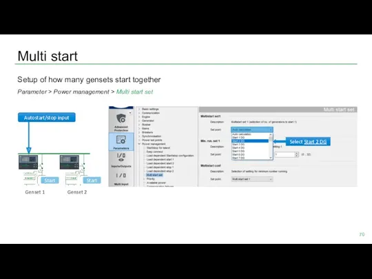
Multi start
Setup of how many gensets start together
Parameter > Power management
Multi start
Setup of how many gensets start together
Parameter > Power management

 Артикуляционная гимнастика.
 Focusing ground penetrating radar images with vertical offset filtering
 Конспект урока по химии в 8 классе по теме Простые вещества - металлы
 Конспект урока в 7-ом классе по географии Движение воды в океане
 Сабриново. Создание сети домов-пансионатов для пожилых людей
 Smart home. Technologies. Automation and robotics
 Автоледи
 Моя семья - моё богатство
 Шкала самооценки Спилбергера-Ханина
 методическое пособие Разложи по порядку
 Порядковое числительное. 6 класс
 Загадки на звуки (Р и Р`) (логопедические упражнения)
 Развитие туризма в Древнем Китае
 Анализ сегментов рынка земли. Характеристики цен на товарном рынке. Определение типа рынка и выбор методов ценообразования
 Игра Найди 10 мышек
 Дерматомиозит/ полимиозит
 Тест. Планеты Солнечной системы
 Дети военных лет
 Опыт проведения православного фестиваля детского художественного творчества Светлая Пасха
 Михаил Юрьевич Лермонтов Бородино
 презентация на тему Игрушки Диск
 Изменение климата
 Презентация Жанры изобразительного искусства
 Минеральные ресурсы мира
 Теорія Надлюдини Фрідріха Ніцше та її місце у романі Кена Кізі Політ над гніздом зозулі
 Электронная база викторин по безопасности.
 Фотосинтез
 Безопасное колесо. Конкурс юных инспекторов движения