- Assembly language

Содержание
- 2. Overview and Aims LMC is a computer simulator … understanding how a computer work To program
- 3. What is in a Computer? Memory CPU I/O
- 4. Simple Computer Processor CPU Memory Data Program instructions I/O Keyboard Display Disk Memory Keyboard I/F CPU
- 5. Memory Each location has an address hold a value Two interfaces address – which location? data
- 6. Quiz – What is the Memory?
- 7. Registers (or Accumulators) Control lines A storage area inside the CPU VERY FAST Used for arguments
- 8. Memory I/O I/O CPU Write a program here
- 9. LMC CPU Structure Visible registers shown in red Accumulators Data for calculation Data Word to/from memory
- 10. Instructions The primitive language of a computer
- 11. Instructions Instruction OpCode Address
- 12. Instructions Opcode: 1 decimal digit Address: two decimal digits – xx Binary versus decimal OpCode Address
- 13. Add and Subtract Instruction ADD Address SUB Address One address and accumulator (ACC) Value at address
- 14. Load and Store Instruction LDA Address STA Address Move data between memory and accumulator (ACC) Load:
- 15. Input and Output Input: ACC ß input value output: output area ß ACC It is more
- 16. Branch Instructions Changes program counter May depend on accumulator (ACC) value BR: PC ß Address BRZ:
- 17. Assembly Code Numbers Memory holds numbers Opcode: 0 to 9 Address: 00 to 99 Instructions in
- 18. LMC Example
- 19. Simple Program x = y + z LDA y ADD z STA x HLT x y
- 20. Running the Simple Program PC IR LDA LDA y ADD z STA x HLT x y
- 21. Running the Simple Program PC IR ADD LDA y ADD z STA x HLT x y
- 22. Running the Simple Program PC ACC IR STA LDA y ADD z STA x HLT x
- 23. Running the Simple Program PC ACC IR HLT LDA y ADD z STA x HLT x
- 24. Practice Exercises Try the first three exercises on the practical sheet
- 25. Fetch-Execute Cycle How the Computer Processes Instructions
- 26. Fetch-Execute Each instruction cycle consists on two subcycles Fetch cycle Load the next instruction (Opcode +
- 27. Fetch Instruction Program counter to address register Read memory at address Memory data to ‘Data’ ‘Data’
- 28. Execute Instruction Decode instruction Address from instruction to ‘address register’ Access memory Data from memory to
- 29. What We Can Learn from LMC How programming language work What a compiler does Why we
- 30. Understanding Variables and Assignment What is a variable? What is on the left hand side of:
- 31. Understanding Variables and Assignment What is a variable? What is on the left hand side of:
- 32. Understanding If and Loops Calculate the address of the next instruction if x > 42: large
- 33. Compiler Compiler translates high level program to low Compiled languages Statically typed Close to machine Examples:
- 34. Why We Need An OS LMC Only one program Program at fixed place in memory No
- 35. Summary of CPU Architecture Memory contains data and program Program counter: address of next instruction Instructions
- 36. Project: Writing an LMC Interpreter
- 38. Скачать презентацию
Overview and Aims
LMC is a computer simulator
… understanding how a computer
Overview and Aims
LMC is a computer simulator
… understanding how a computer
What is in a Computer?
Memory
CPU
I/O
What is in a Computer?
Memory
CPU
I/O
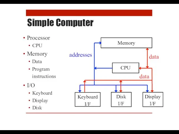
Simple Computer
Processor
CPU
Memory
Data
Program instructions
I/O
Keyboard
Display
Disk
Memory
Keyboard I/F
CPU
Disk I/F
Display I/F
data
data
addresses
Simple Computer
Processor
CPU
Memory
Data
Program instructions
I/O
Keyboard
Display
Disk
Memory
Keyboard I/F
CPU
Disk I/F
Display I/F
data
data
addresses
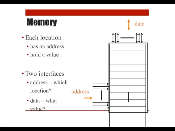
Memory
Each location
has an address
hold a value
Two interfaces
address – which location?
data –
Memory
Each location
has an address
hold a value
Two interfaces
address – which location?
data –
Quiz – What is the Memory?
Quiz – What is the Memory?
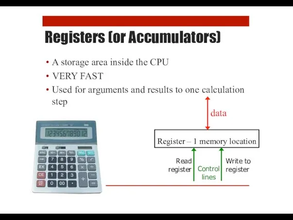
Registers (or Accumulators)
Control lines
A storage area inside the CPU
VERY FAST
Used for
Registers (or Accumulators)
Control lines
A storage area inside the CPU
VERY FAST
Used for
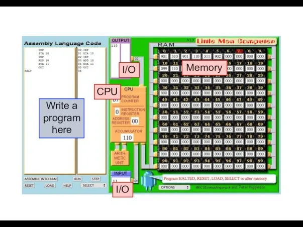
Memory
I/O
I/O
CPU
Write a program here
Memory
I/O
I/O
CPU
Write a program here
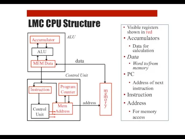
LMC CPU Structure
Visible registers shown in red
Accumulators
Data for calculation
Data
Word to/from memory
PC
Address
LMC CPU Structure
Visible registers shown in red
Accumulators
Data for calculation
Data
Word to/from memory
PC
Address
Instructions
The primitive language of a computer
Instructions
The primitive language of a computer
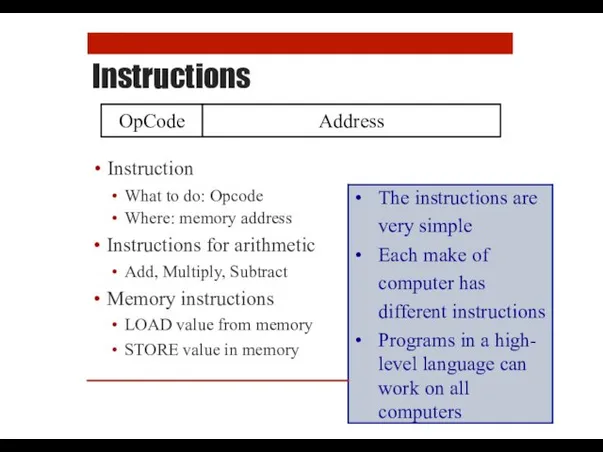
Instructions
Instruction
OpCode
Address
Instructions
Instruction
OpCode
Address
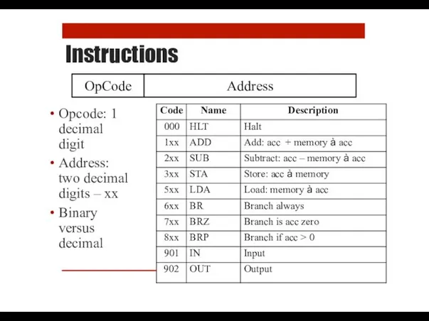
Instructions
Opcode: 1
decimal
digit
Address:
two decimal
digits – xx
Binary
versus
decimal
OpCode
Address
Instructions
Opcode: 1
decimal
digit
Address:
two decimal
digits – xx
Binary
versus
decimal
OpCode
Address
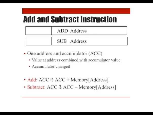
Add and Subtract Instruction
ADD Address
SUB Address
One address and accumulator (ACC)
Value at address combined
Add and Subtract Instruction
ADD Address
SUB Address
One address and accumulator (ACC)
Value at address combined
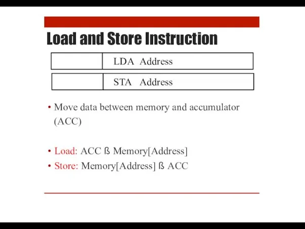
Load and Store Instruction
LDA Address
STA Address
Move data between memory and accumulator (ACC)
Load: ACC
Load and Store Instruction
LDA Address
STA Address
Move data between memory and accumulator (ACC)
Load: ACC
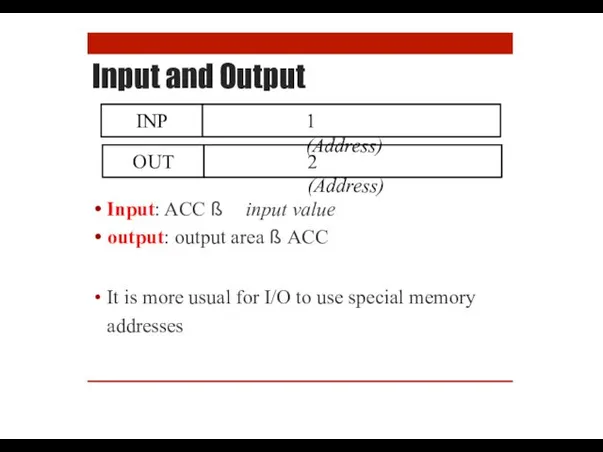
Input and Output
Input: ACC ß input value
output: output area ß ACC
It is
Input and Output
Input: ACC ß input value
output: output area ß ACC
It is
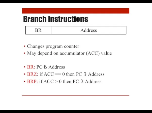
Branch Instructions
Changes program counter
May depend on accumulator (ACC) value
BR: PC ß
Branch Instructions
Changes program counter
May depend on accumulator (ACC) value
BR: PC ß
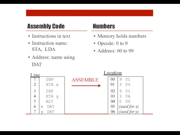
Assembly Code
Numbers
Memory holds numbers
Opcode: 0 to 9
Address: 00 to 99
Instructions in
Assembly Code
Numbers
Memory holds numbers
Opcode: 0 to 9
Address: 00 to 99
Instructions in
LMC Example
LMC Example
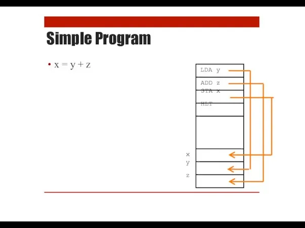
Simple Program
x = y + z
LDA y
ADD z
STA x HLT
x
y z
Simple Program
x = y + z
LDA y
ADD z
STA x HLT
x
y z
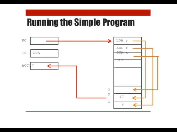
Running the Simple Program
PC
IR
LDA
LDA y
ADD z
STA x HLT
x
y z
17
9
ACC 17
Running the Simple Program
PC
IR
LDA
LDA y
ADD z
STA x HLT
x
y z
17
9
ACC 17

Running the Simple Program
PC
IR
ADD
LDA y
ADD z
STA x HLT
x
y z
17
9
ACC 2167
Running the Simple Program
PC
IR
ADD
LDA y
ADD z
STA x HLT
x
y z
17
9
ACC 2167
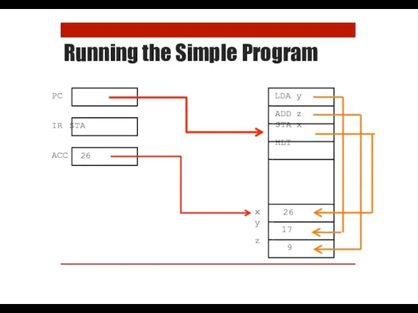
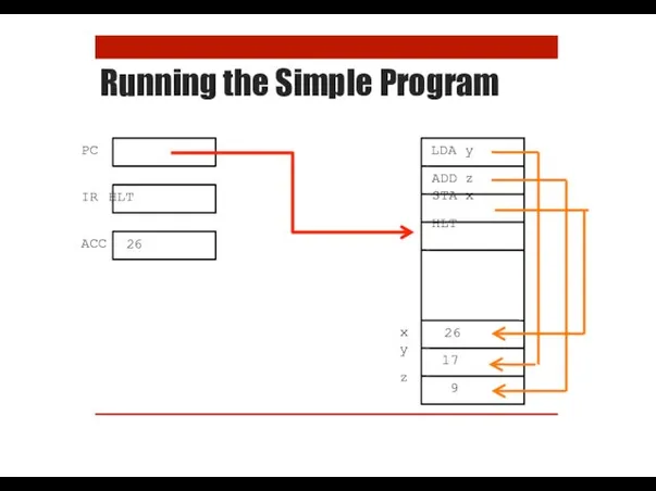
Running the Simple Program
PC
ACC
IR STA
LDA y
ADD z
STA x HLT
x
y z
26
26
17
9
Running the Simple Program
PC
ACC
IR STA
LDA y
ADD z
STA x HLT
x
y z
26
26
17
9
Running the Simple Program
PC
ACC
IR HLT
LDA y
ADD z
STA x HLT
x
y z
26
26
17
9
Running the Simple Program
PC
ACC
IR HLT
LDA y
ADD z
STA x HLT
x
y z
26
26
17
9
Practice Exercises
Try the first three exercises on the practical sheet
Practice Exercises
Try the first three exercises on the practical sheet
Fetch-Execute Cycle
How the Computer Processes Instructions
Fetch-Execute Cycle
How the Computer Processes Instructions
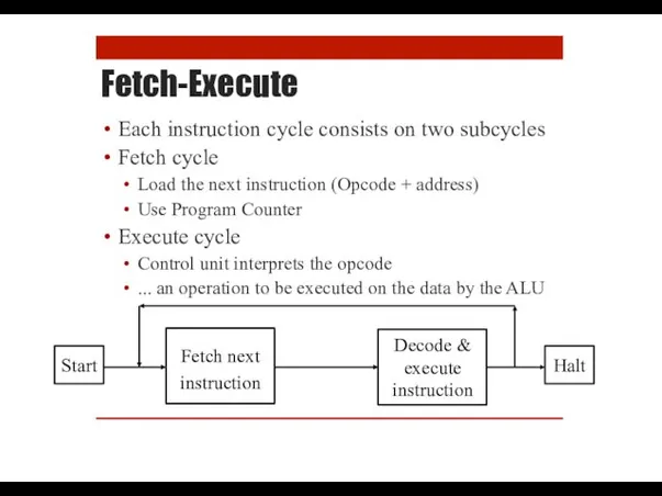
Fetch-Execute
Each instruction cycle consists on two subcycles
Fetch cycle
Load the next instruction
Fetch-Execute
Each instruction cycle consists on two subcycles
Fetch cycle
Load the next instruction
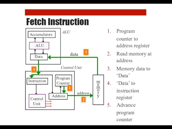
Fetch Instruction
Program
counter to address register
Read memory at address
Memory data to ‘Data’
‘Data’
Fetch Instruction
Program
counter to address register
Read memory at address
Memory data to ‘Data’
‘Data’
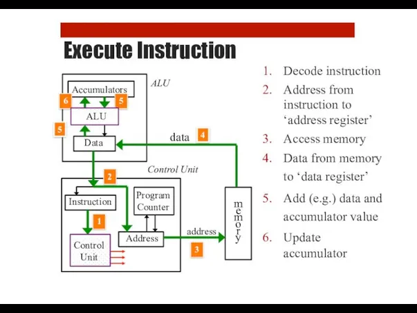
Execute Instruction
Decode instruction
Address from instruction to ‘address register’
Access memory
Data from memory
Execute Instruction
Decode instruction
Address from instruction to ‘address register’
Access memory
Data from memory
What We Can Learn from LMC
How programming language work
What a compiler
What We Can Learn from LMC
How programming language work
What a compiler
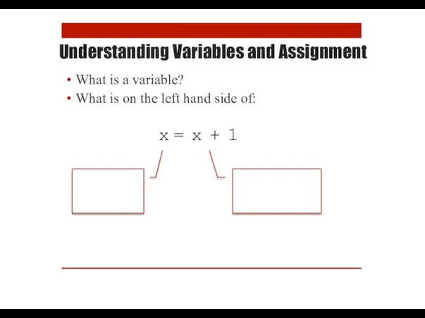
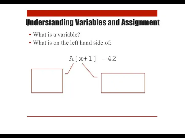
Understanding Variables and Assignment
What is a variable?
What is on the left
Understanding Variables and Assignment
What is a variable?
What is on the left
Understanding Variables and Assignment
What is a variable?
What is on the left
Understanding Variables and Assignment
What is a variable?
What is on the left
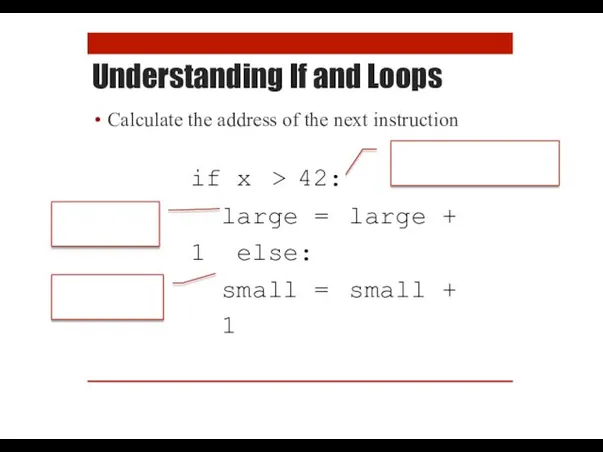
Understanding If and Loops
Calculate the address of the next instruction
if x > 42:
large
Understanding If and Loops
Calculate the address of the next instruction
if x > 42:
large
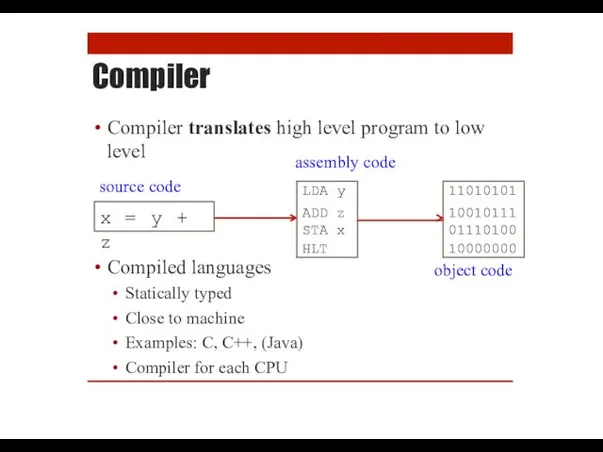
Compiler
Compiler translates high level program to low
Compiled languages
Statically typed
Close to machine
Examples:
Compiler
Compiler translates high level program to low
Compiled languages
Statically typed
Close to machine
Examples:
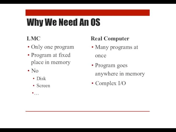
Why We Need An OS
LMC
Only one program
Program at fixed place in
Why We Need An OS
LMC
Only one program
Program at fixed place in
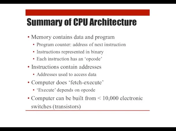
Summary of CPU Architecture
Memory contains data and program
Program counter: address of
Summary of CPU Architecture
Memory contains data and program
Program counter: address of
Project: Writing an LMC Interpreter
Project: Writing an LMC Interpreter
 Презентация к 180-летию Альфреда Нобеля
 Konferentsia_17_02_22 (1)
 Дидактический материал для преодоления нарушения слоговой структуры слова у детей 4-6 лет
 Европейский удильщик или морской черт
 Воспитание и обучение в Древней Индии
 Потепление в СПБ или Зима без снега
 Irregular verbs. Game
 Основы программирования. Вложенные циклы
 Культура России первой половины 19 века
 Философия и общественные науки в Новое и Новейшее время
 Гpузовые стропы общего назначения
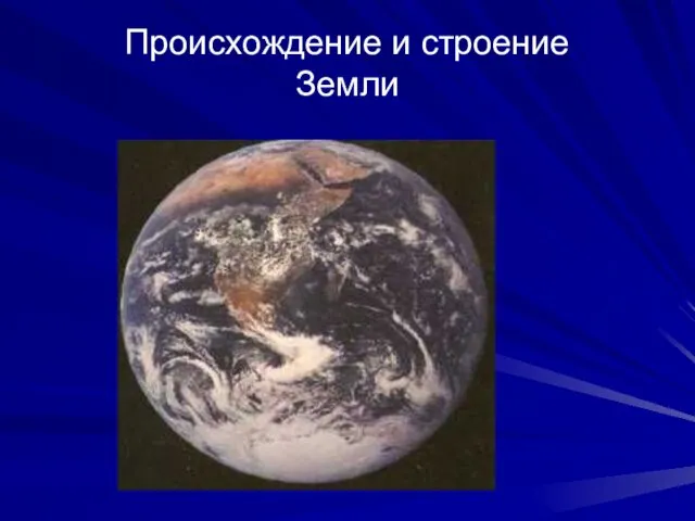 Происхождение Земли. (Лекция 6)
 Организация и ведение научно- исследовательской работы среди школьников
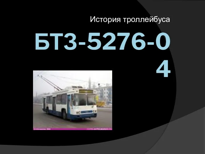 История троллейбуса БТЗ-5276-04
 Я - выбираю спорт!
 Построение сложных запросов. Инсерт
 Социальные движения в первой половине XVIII века
 Спасский Староярмарочный Собор. Моя малая Родина. Моё спасение
 АНАЛИТИЧЕСКИЙ ОТЧЕТ о результатах итоговых контрольных работ
 Тема Родительское собрание
 Усилители. Усилительный каскад на БПТ с ОЭ
 проект учащегося 3 класса Четверткова Георгия
 Наши дети – наше будущее
 Волейбол. Совершенствование нижней прямой подачи
 Метод координат
 Презентация для педагогов
 Приобщение детей к татарской и русской культуре в подготовительной группе детского сада
 Военно-морской флот Российской Федерации