- CD Desiccant Dryers for High Quality Air Applications

Содержание
- 2. Smallest - CD 2 = 2 l/s or 4.24 cfm Largest - CD 280 = 280
- 3. Desiccant Technology Desiccant Technology Desiccant Absortion Absorption process Absorption process Purge Process Purge Process Working principles
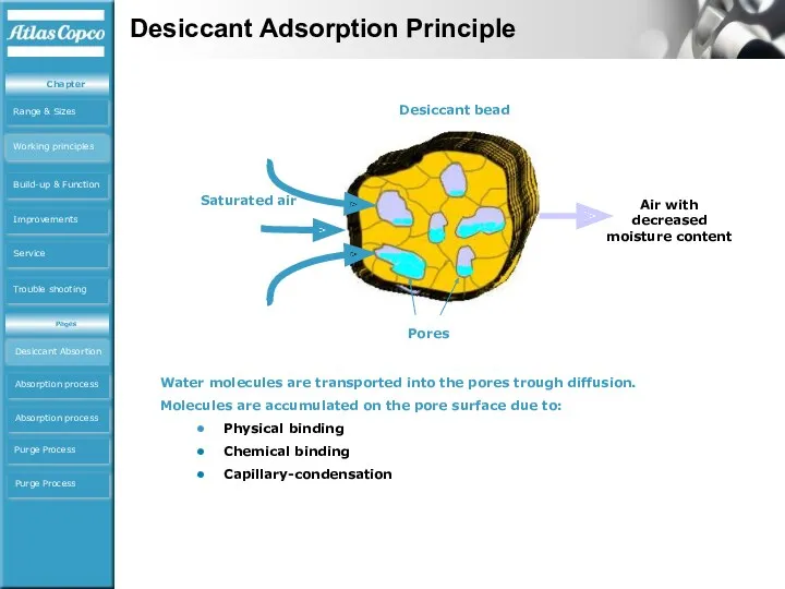
- 4. Desiccant bead Pores Saturated air Air with decreased moisture content Water molecules are transported into the
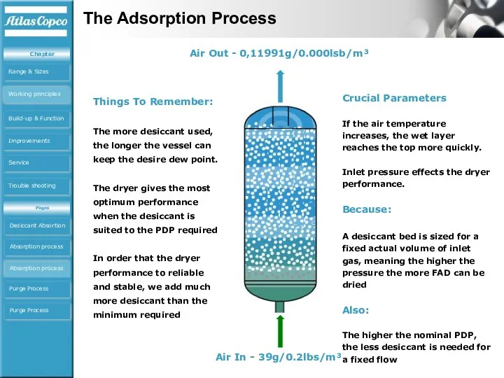
- 5. Air In - 39g/0.2lbs/m³ Air Out - 0,11991g/0.000lsb/m³ Water vapor transfers to the desiccant because… desiccant
- 6. Things To Remember: The more desiccant used, the longer the vessel can keep the desire dew
- 7. l/s Desiccant Purging 1/2 CYCLE TIME Equalisation The Phases Of The Purge Process The Purge Process
- 8. Important Things To Know About Purge The actual flow rate (not FAD) of purge air through
- 9. The CD Desiccant type air dryers utilize chemicals beads, called desiccant, to adsorb water vapour from
- 10. The basic operation of a the CD dryer consists of one drying cycle and one regeneration
- 11. CD7-60 Build up & Function CD7-65 Build up CD65-280 Build up CD65-280 Build up CD65-280 Build
- 12. CD65-280 Working principal CD7-65 Working CD7-65 Working CD65-280 Working ICD65-280 Working Working principles CD65-280CDAnimation.exe
- 13. CD65-280 Working principal CD65-280ICDAnimation.exe CD7-65 Working CD7-65 Working CD65-280 Working ICD65-280 Working Working principles
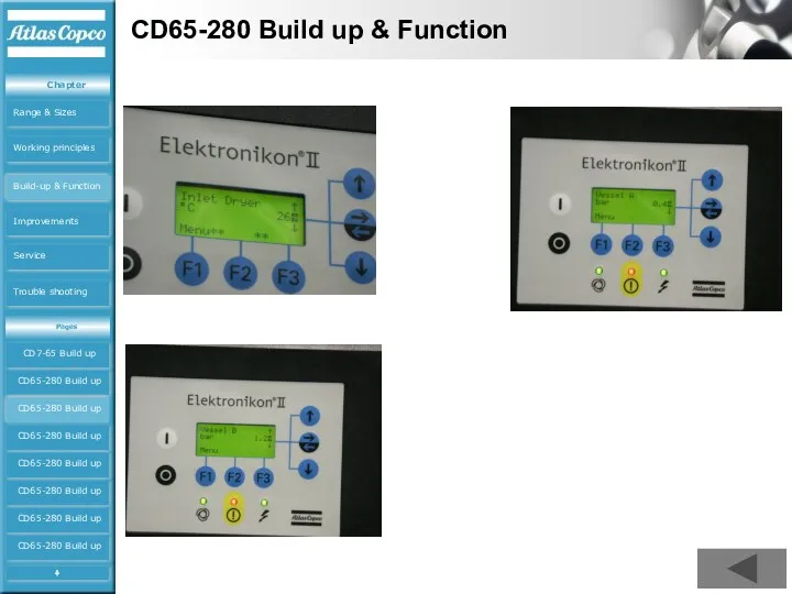
- 14. CD65-280 Build up & Function CD7-65 Build up CD65-280 Build up CD65-280 Build up CD65-280 Build
- 15. CD65-280 Build up & Function Nozzle Non Return valve Dew Transmitter CD65-280 Build up CD65-280 Build
- 16. CD65-280 Build up & Function Cleaning of sensor only with Aceton CD65-280 Build up CD65-280 Build
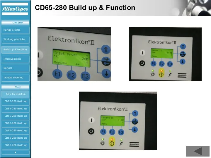
- 17. CD65-280 Build up & Function CD65-280 Build up CD65-280 Build up CD65-280 Build up CD65-280 Build
- 18. CD65-280 Build up & Function Vessel “A” under pressure Vessel “B” regenerating Warning : sensor error
- 19. CD65-280 Build up & Function Warnings Dewpoint Failure No dewpoint CD65-280 Build up CD65-280 Build up
- 20. CD65-280 Build up & Function Service CD65-280 Build up CD65-280 Build up CD65-280 Build up CD65-280
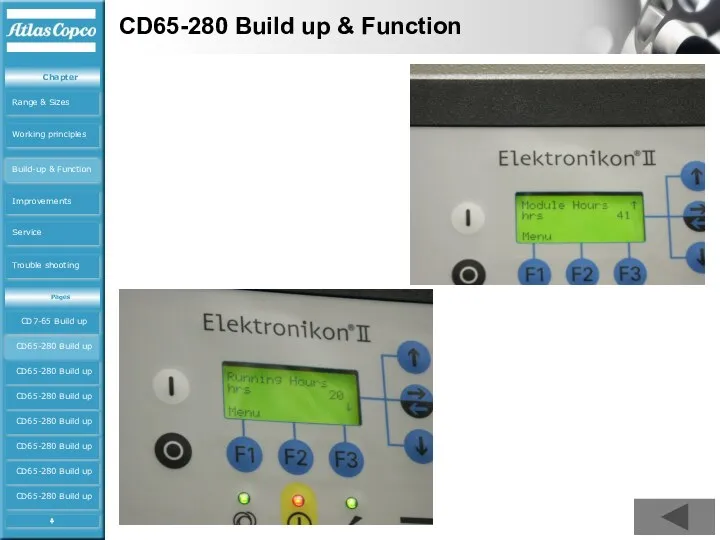
- 21. CD65-280 Build up & Function CD7-65 Build up CD65-280 Build up CD65-280 Build up CD65-280 Build
- 22. CD65-280 Build up & Function CD7-65 Build up CD65-280 Build up CD65-280 Build up CD65-280 Build
- 23. CD65-280 Build up & Function CD7-65 Build up CD65-280 Build up CD65-280 Build up CD65-280 Build
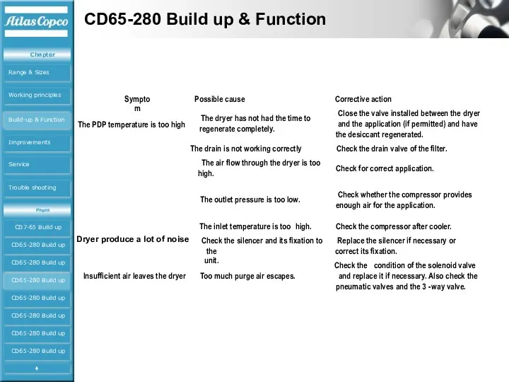
- 24. CD65-280 Build up & Function Symptom Possible cause Corrective action The dryer has not had the
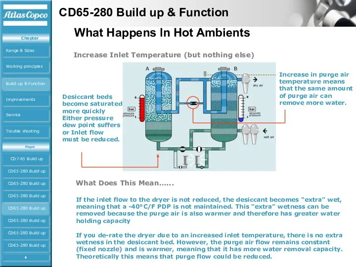
- 25. Increase Inlet Temperature (but nothing else) Desiccant beds become saturated more quickly Either pressure dew point
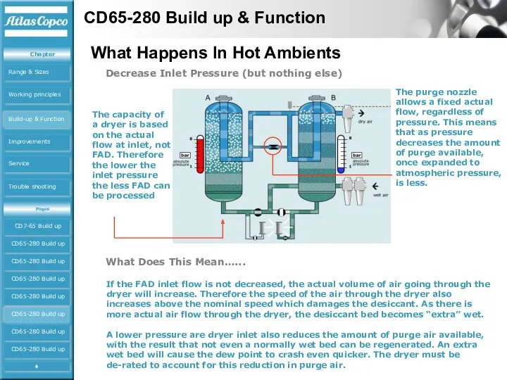
- 26. Decrease Inlet Pressure (but nothing else) The capacity of a dryer is based on the actual
- 27. Increase Required PDP (but nothing else) When air passes through a regenerated desiccant bed, the PDP
- 28. Using Correction Factors - Do’s and Don’ts DO Remember that for inlet temperatures greater than 50°C,
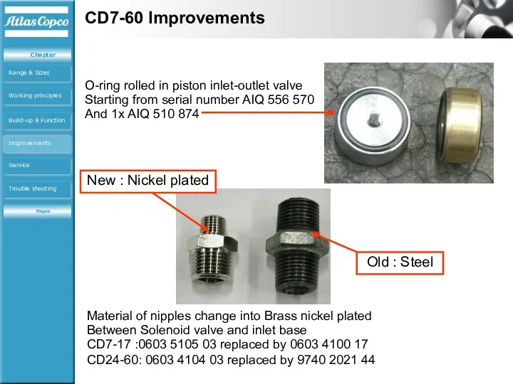
- 29. CD7-60 Improvements O-ring rolled in piston inlet-outlet valve Starting from serial number AIQ 556 570 And
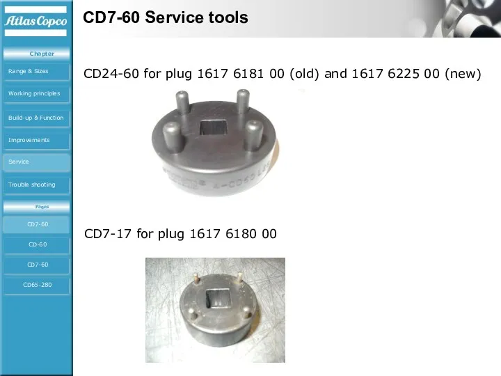
- 30. CD7-60 Service tools CD24-60 for plug 1617 6181 00 (old) and 1617 6225 00 (new) CD7-17
- 31. CD7-60 Service tools Valve seat CD7-60 2903 0014 01 is for CD7-17 2903 0014 02 is
- 32. CD7-60 Service Kits Service kits CD7-60 Tools CD-60 Tools CD7-60 Kits CD65-280 Kits Service
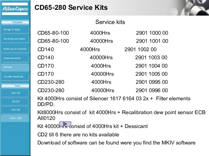
- 33. CD65-280 Service Kits CD65-80-100 4000Hrs 2901 1000 00 CD65-80-100 40000Hrs 2901 1001 00 CD140 4000Hrs 2901
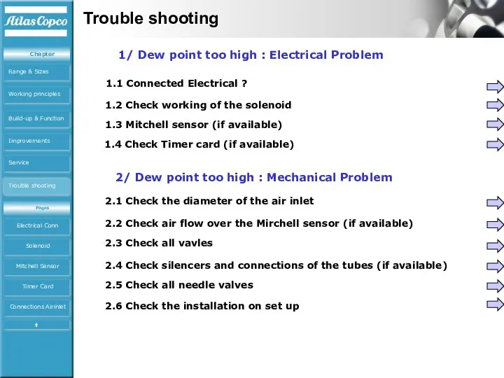
- 34. Trouble shooting 1/ Dew point too high : Electrical Problem 2/ Dew point too high :
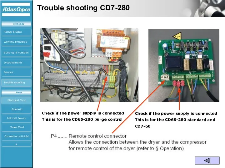
- 35. Trouble shooting CD7-280 Check if the power supply is connected This is for the CD65-280 purge
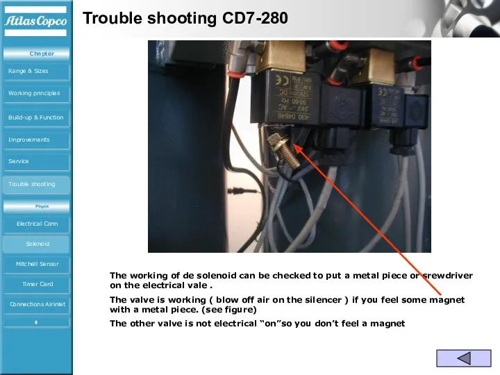
- 36. Trouble shooting CD7-280 The working of de solenoid can be checked to put a metal piece
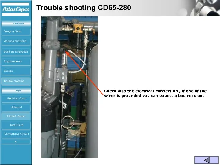
- 37. Trouble shooting CD65-280 Check also the electrical connection , if one of the wires is grounded
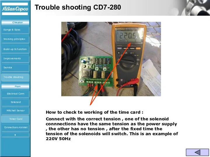
- 38. Trouble shooting CD7-280 How to check te working of the time card : Connect with the
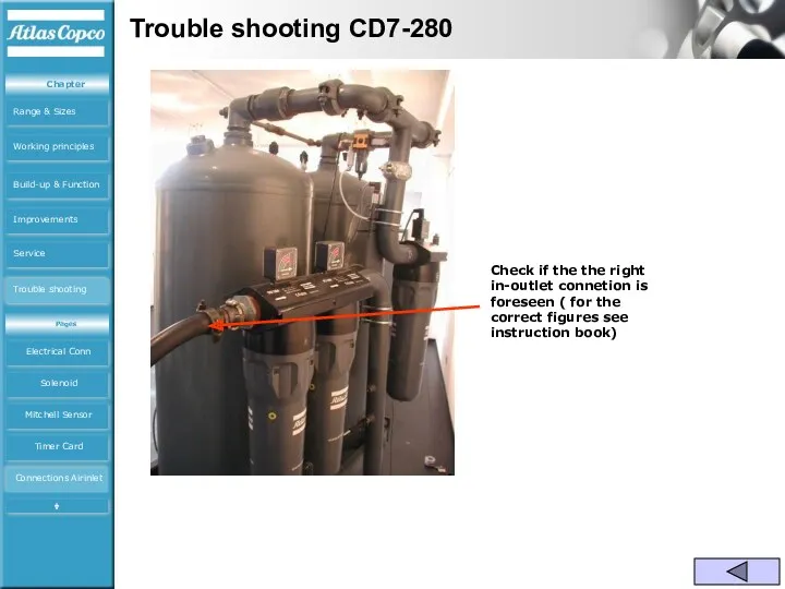
- 39. Trouble shooting CD7-280 Check if the the right in-outlet connetion is foreseen ( for the correct
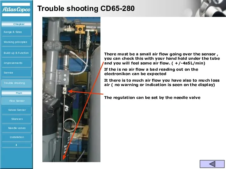
- 40. Trouble shooting CD65-280 There must be a small air flow going over the sensor , you
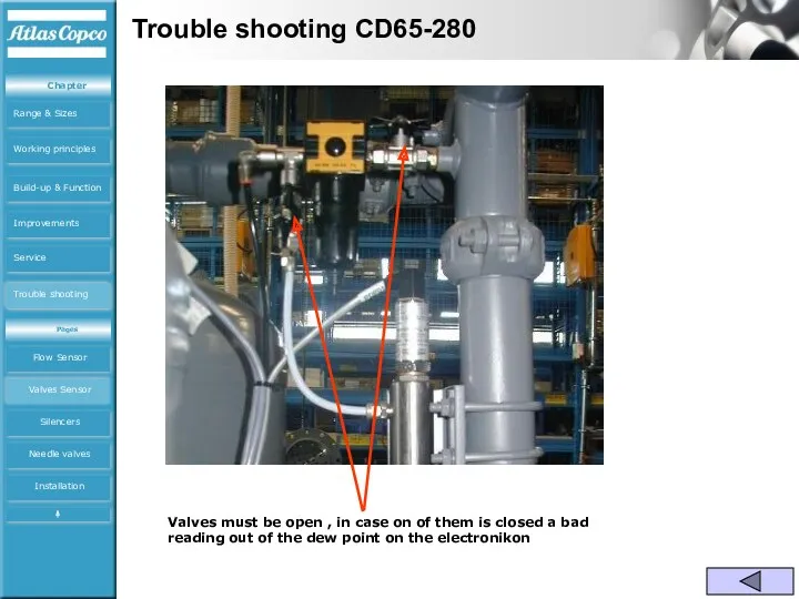
- 41. Trouble shooting CD65-280 Valves must be open , in case on of them is closed a
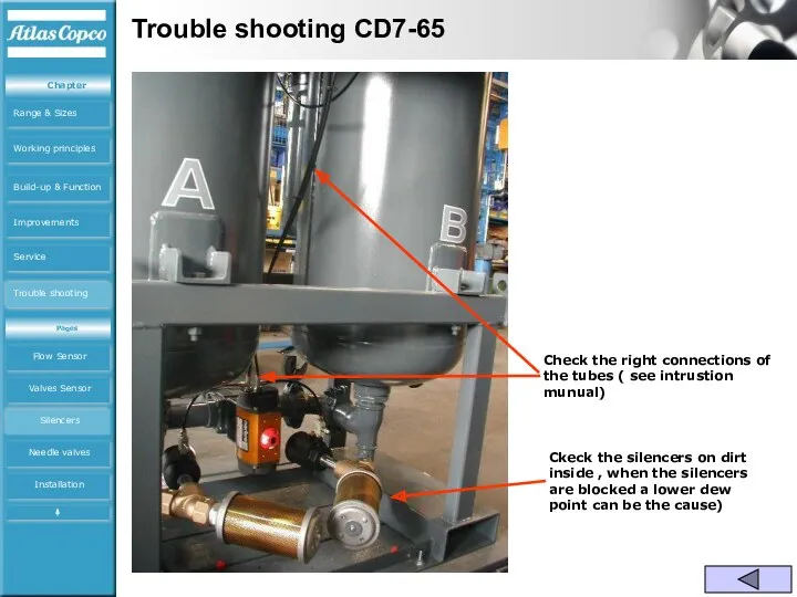
- 42. Trouble shooting CD7-65 Check the right connections of the tubes ( see intrustion munual) Ckeck the
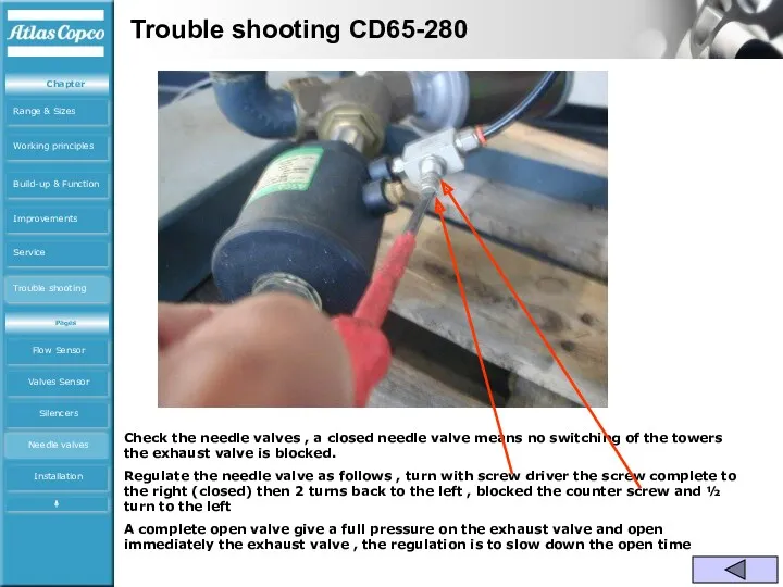
- 43. Trouble shooting CD65-280 Check the needle valves , a closed needle valve means no switching of
- 45. Скачать презентацию
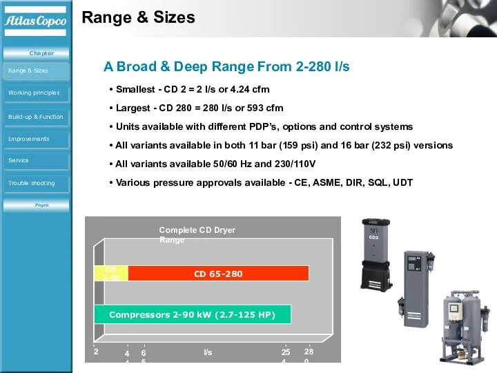
Smallest - CD 2 = 2 l/s or 4.24 cfm
Smallest - CD 2 = 2 l/s or 4.24 cfm
Desiccant Technology
Desiccant Technology
Desiccant Absortion
Absorption process
Absorption process
Purge Process
Purge Process
Working principles
Desiccant Technology
Desiccant Technology
Desiccant Absortion
Absorption process
Absorption process
Purge Process
Purge Process
Working principles
Desiccant bead
Pores
Saturated air
Air with decreased moisture content
Water molecules are transported
Desiccant bead
Pores
Saturated air
Air with decreased moisture content
Water molecules are transported
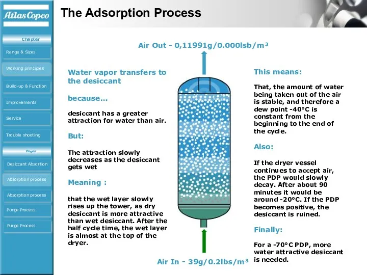
Air In - 39g/0.2lbs/m³
Air Out - 0,11991g/0.000lsb/m³
Water vapor transfers to the
Air In - 39g/0.2lbs/m³
Air Out - 0,11991g/0.000lsb/m³
Water vapor transfers to the
Things To Remember:
The more desiccant used, the longer the vessel can
Things To Remember:
The more desiccant used, the longer the vessel can
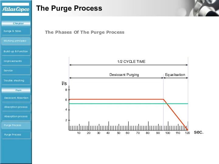
l/s
Desiccant Purging
1/2 CYCLE TIME
Equalisation
The Phases Of The Purge Process
The Purge Process
Desiccant
l/s
Desiccant Purging
1/2 CYCLE TIME
Equalisation
The Phases Of The Purge Process
The Purge Process
Desiccant
Important Things To Know About Purge
The actual flow rate (not
Important Things To Know About Purge
The actual flow rate (not
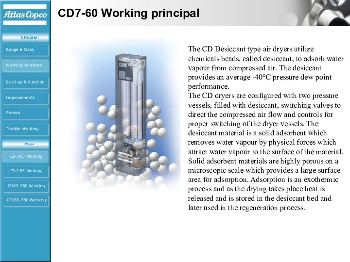
The CD Desiccant type air dryers utilize chemicals beads, called desiccant,
The CD Desiccant type air dryers utilize chemicals beads, called desiccant,
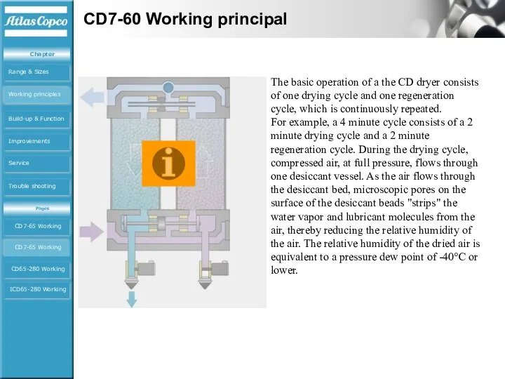
The basic operation of a the CD dryer consists of one
The basic operation of a the CD dryer consists of one
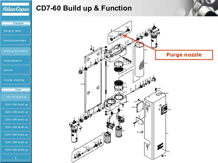
CD7-60 Build up & Function
CD7-65 Build up
CD65-280 Build up
CD65-280
CD7-60 Build up & Function
CD7-65 Build up
CD65-280 Build up
CD65-280

CD65-280 Working principal
CD7-65 Working
CD7-65 Working
CD65-280 Working
ICD65-280 Working
Working principles
CD65-280CDAnimation.exe
CD65-280 Working principal
CD7-65 Working
CD7-65 Working
CD65-280 Working
ICD65-280 Working
Working principles
CD65-280CDAnimation.exe
CD65-280 Working principal
CD65-280ICDAnimation.exe
CD7-65 Working
CD7-65 Working
CD65-280 Working
ICD65-280 Working
Working principles
CD65-280 Working principal
CD65-280ICDAnimation.exe
CD7-65 Working
CD7-65 Working
CD65-280 Working
ICD65-280 Working
Working principles
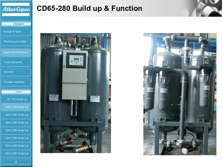
CD65-280 Build up & Function
CD7-65 Build up
CD65-280 Build up
CD65-280
CD65-280 Build up & Function
CD7-65 Build up
CD65-280 Build up
CD65-280
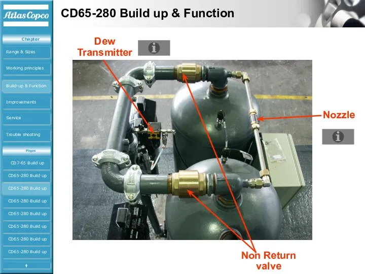
CD65-280 Build up & Function
Nozzle
Non Return valve
Dew Transmitter
CD65-280 Build up
CD65-280 Build
CD65-280 Build up & Function
Nozzle
Non Return valve
Dew Transmitter
CD65-280 Build up
CD65-280 Build
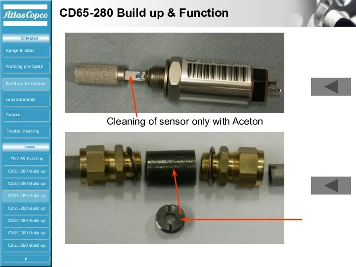
CD65-280 Build up & Function
Cleaning of sensor only with Aceton
CD65-280 Build
CD65-280 Build up & Function
Cleaning of sensor only with Aceton
CD65-280 Build
CD65-280 Build up & Function
CD65-280 Build up
CD65-280 Build up
CD65-280 Build up
CD65-280
CD65-280 Build up & Function
CD65-280 Build up
CD65-280 Build up
CD65-280 Build up
CD65-280
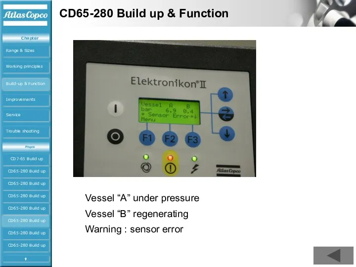
CD65-280 Build up & Function
Vessel “A” under pressure
Vessel “B” regenerating
Warning :
CD65-280 Build up & Function
Vessel “A” under pressure
Vessel “B” regenerating
Warning :
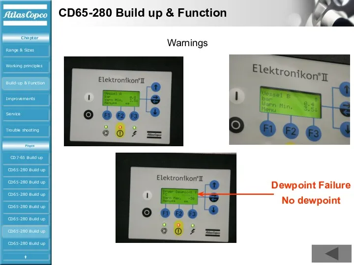
CD65-280 Build up & Function
Warnings
Dewpoint Failure
No dewpoint
CD65-280 Build up
CD65-280 Build
CD65-280 Build up & Function
Warnings
Dewpoint Failure
No dewpoint
CD65-280 Build up
CD65-280 Build
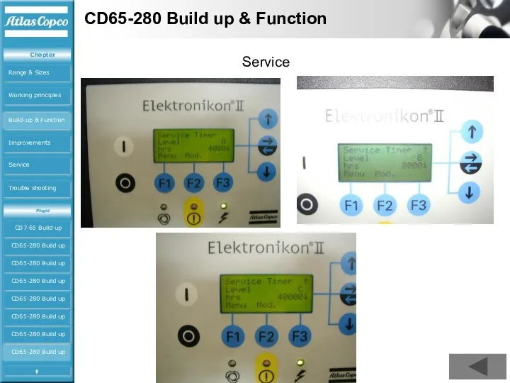
CD65-280 Build up & Function
Service
CD65-280 Build up
CD65-280 Build up
CD65-280 Build up
CD65-280
CD65-280 Build up & Function
Service
CD65-280 Build up
CD65-280 Build up
CD65-280 Build up
CD65-280
CD65-280 Build up & Function
CD7-65 Build up
CD65-280 Build up
CD65-280 Build
CD65-280 Build up & Function
CD7-65 Build up
CD65-280 Build up
CD65-280 Build
CD65-280 Build up & Function
CD7-65 Build up
CD65-280 Build up
CD65-280 Build
CD65-280 Build up & Function
CD7-65 Build up
CD65-280 Build up
CD65-280 Build
CD65-280 Build up & Function
CD7-65 Build up
CD65-280 Build up
CD65-280 Build
CD65-280 Build up & Function
CD7-65 Build up
CD65-280 Build up
CD65-280 Build
CD65-280 Build up & Function
Symptom
Possible cause
Corrective action
The
CD65-280 Build up & Function
Symptom
Possible cause
Corrective action
The
Increase Inlet Temperature (but nothing else)
Desiccant beds become saturated more quickly
Either
Increase Inlet Temperature (but nothing else)
Desiccant beds become saturated more quickly
Either
Decrease Inlet Pressure (but nothing else)
The capacity of a dryer is
Decrease Inlet Pressure (but nothing else)
The capacity of a dryer is
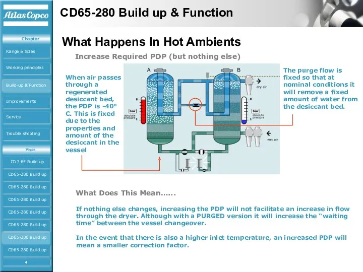
Increase Required PDP (but nothing else)
When air passes through a regenerated
Increase Required PDP (but nothing else)
When air passes through a regenerated
Using Correction Factors - Do’s and Don’ts
DO
Remember that for inlet
Using Correction Factors - Do’s and Don’ts
DO
Remember that for inlet
CD7-60 Improvements
O-ring rolled in piston inlet-outlet valve
Starting from serial number
CD7-60 Improvements
O-ring rolled in piston inlet-outlet valve
Starting from serial number
CD7-60 Service tools
CD24-60 for plug 1617 6181 00 (old) and 1617
CD7-60 Service tools
CD24-60 for plug 1617 6181 00 (old) and 1617
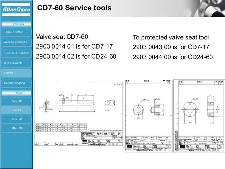
CD7-60 Service tools
Valve seat CD7-60
2903 0014 01 is for CD7-17
2903 0014
CD7-60 Service tools
Valve seat CD7-60
2903 0014 01 is for CD7-17
2903 0014
CD7-60 Service Kits
Service kits
CD7-60 Tools
CD-60 Tools
CD7-60 Kits
CD65-280 Kits
Service
CD7-60 Service Kits
Service kits
CD7-60 Tools
CD-60 Tools
CD7-60 Kits
CD65-280 Kits
Service
CD65-280 Service Kits
CD65-80-100 4000Hrs 2901 1000 00
CD65-80-100 40000Hrs 2901 1001 00
CD140
CD65-280 Service Kits
CD65-80-100 4000Hrs 2901 1000 00
CD65-80-100 40000Hrs 2901 1001 00
CD140
Trouble shooting
1/ Dew point too high : Electrical Problem
2/ Dew
Trouble shooting
1/ Dew point too high : Electrical Problem
2/ Dew
Trouble shooting CD7-280
Check if the power supply is connected
This is
Trouble shooting CD7-280
Check if the power supply is connected
This is
Trouble shooting CD7-280
The working of de solenoid can be checked to
Trouble shooting CD7-280
The working of de solenoid can be checked to
Trouble shooting CD65-280
Check also the electrical connection , if one of
Trouble shooting CD65-280
Check also the electrical connection , if one of
Trouble shooting CD7-280
How to check te working of the time card
Trouble shooting CD7-280
How to check te working of the time card
Trouble shooting CD7-280
Check if the the right in-outlet connetion is foreseen
Trouble shooting CD7-280
Check if the the right in-outlet connetion is foreseen
Trouble shooting CD65-280
There must be a small air flow going over
Trouble shooting CD65-280
There must be a small air flow going over
Trouble shooting CD65-280
Valves must be open , in case on of
Trouble shooting CD65-280
Valves must be open , in case on of
Trouble shooting CD7-65
Check the right connections of the tubes ( see
Trouble shooting CD7-65
Check the right connections of the tubes ( see
Trouble shooting CD65-280
Check the needle valves , a closed needle valve
Trouble shooting CD65-280
Check the needle valves , a closed needle valve
 Русский язык. Лексика и грамматика
 Игра За сутки до.... Проект
 Поставка по контракту. Заключение и исполнение. Ответственность
 Оңтүстік Қазақстан және Батыс Қазақстанда таралған пайдалы өсімдіктер
 Фәнис Яруллин
 Теория коллектива
 Воспитательное пространство: основные характеристики
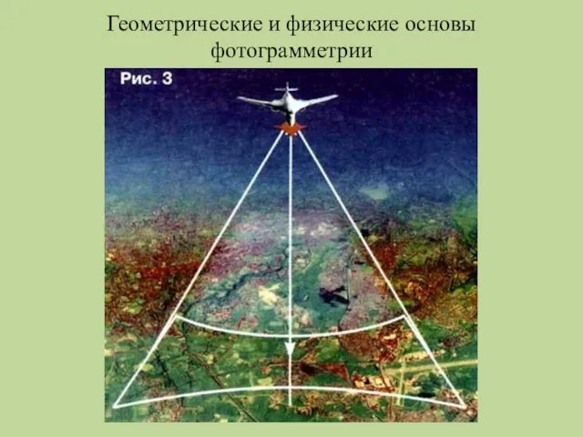 Фотограмметрия. Геометрические и физические основы фотограмметрии. (Лекция 2)
 Новогодняя ночь
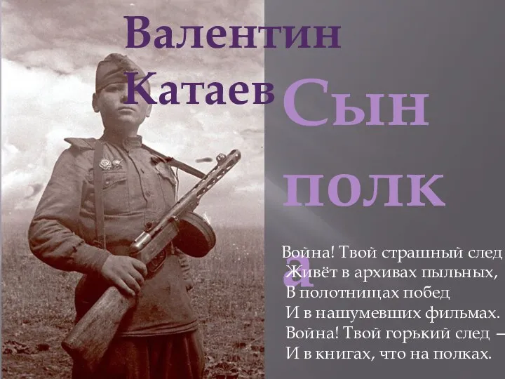 Сын полка. 16.04
 Электронные деловые коммуникации
 Здоровое питание школьника презентация
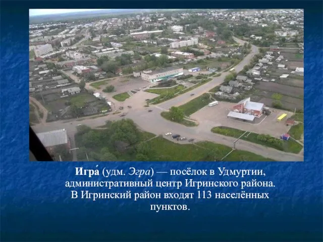 Игра́ (удм. Эгра) — посёлок в Удмуртии
 Окончание и основа. 2 класс
 Творческий отчет
 Притча Светланы Копыловой Окно
 Полимерные материалы и изделия
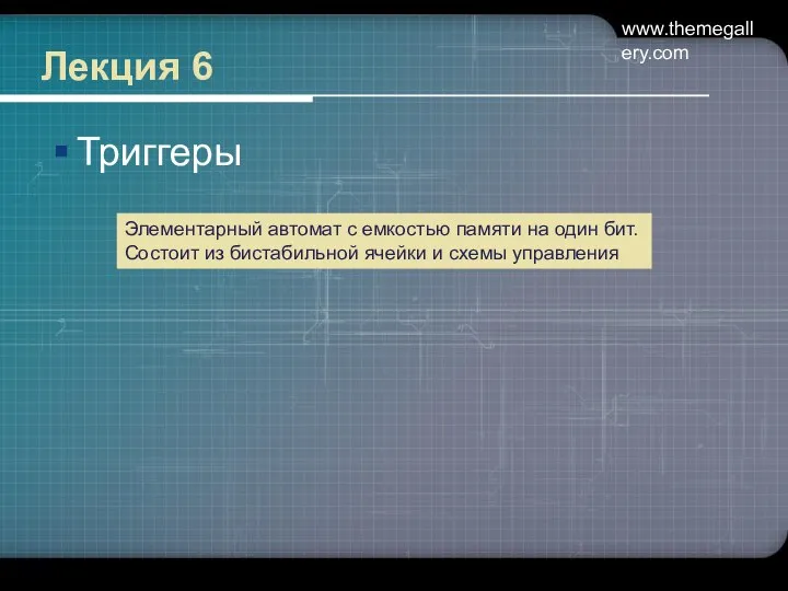 Триггеры. (Лекция 6)
 Обнинская АЭС
 Инструкция: Как стать хорошим человеком
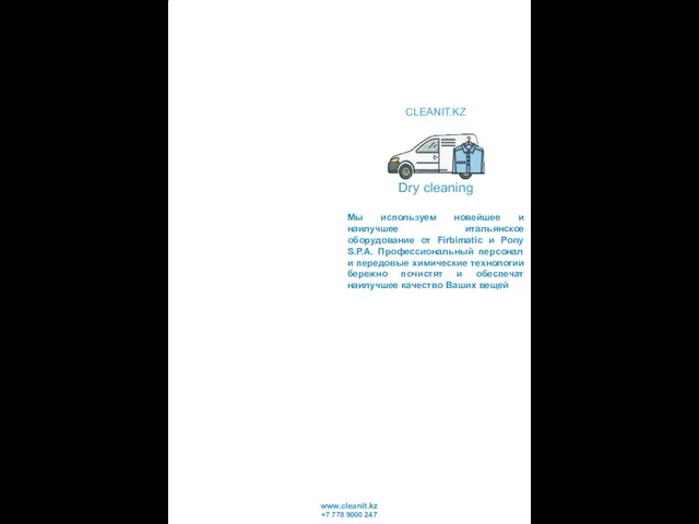 Dry cleaning. Профессиональный персонал и передовые химические технологии бережно почистят Ваши вещи
 С Благовещеньем!
 Источники финансирования предпринимательства
 Потенциал. Разность потенциалов. Связь напряжённости поля с разностью потенциалов
 Халықаралық жария құқық субъектілері
 внеурочное мероприятие в 1 классе Турнир Смекалочка
 Детский воспитательный коллектив
 Алльфа страхование. Выявление ключевых проблем филиала и их решение