- CEO:Current Engine Option. NEO: New Engine Option

Содержание
- 2. Introduction Flight Ops Summary Page July 28 2016 This document provides a quick overview of the
- 3. = Pilot qualified on A320 CEO and NEO Flight Crew Training Level B Level A Page
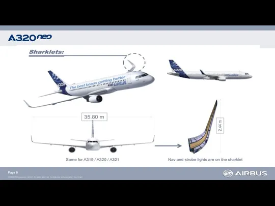
- 4. Sharklets New engines High Bypass ratio Lower Noise Levels Complete system redesign (pylon, nacelle, bleed) 15%
- 5. Adapted systems ATA22: Autoflight ATA27: Flight Control ATA31: Indicating/Recording System Wing structure, fuselage and cabin adaptations
- 6. Page
- 7. Hardware modifications Software modifications Page Modifications Minimum cange, Maximum commonality with A320 CEO
- 8. Propulsion system Powerplant New engine architecture High by-pass ratio Page
- 9. Power Plant Powerplant Page
- 10. Engine Primary Parameters Powerplant Page N1 instead of EPR COOLING memo Bleed Configuration
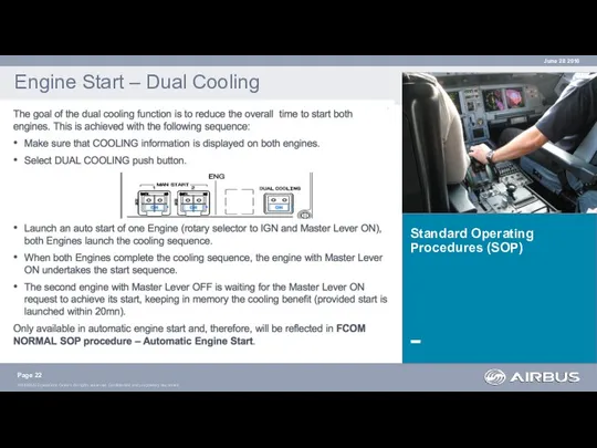
- 11. Dual Cooling Powerplant Page Dual Cooling function is armed when the DUAL COOLING pb-sw is ON.
- 12. Dual Cooling Powerplant Page Dual Cooling function is available in a dedicated envelope of use depending
- 13. Electrical Power Integrated Drive Generator (IDG) Derived from A340-500/600 for better reliability Page
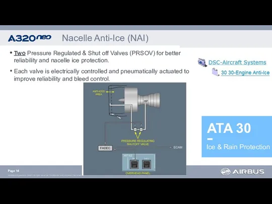
- 14. Ice & Rain Protection Nacelle Anti-Ice (NAI) Two Pressure Regulated & Shut off Valves (PRSOV) for
- 15. New Engine Bleed Air System (EBAS) architecture. Electro-pneumatically valves (instead of fully pneumatically). Engine Bleed Air
- 16. Standard Operating Procedures (SOP) Limitations (LIM) Supplementary Procedures (SUP) Abnormal Procedures (ABN)
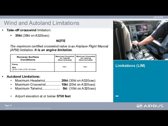
- 17. Limitations (LIM) Wind and Autoland Limitations Page July 28 2016 Take-off crosswind limitation: 35kt (38kt on
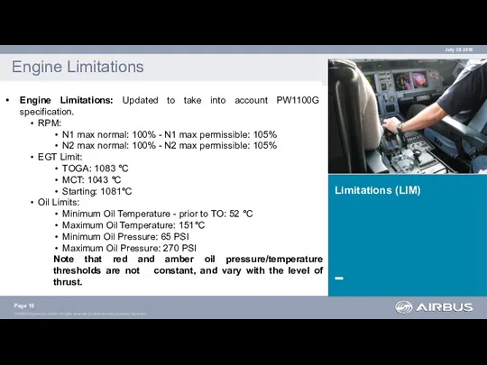
- 18. Limitations (LIM) Engine Limitations Page Engine Limitations: Updated to take into account PW1100G specification. RPM: N1
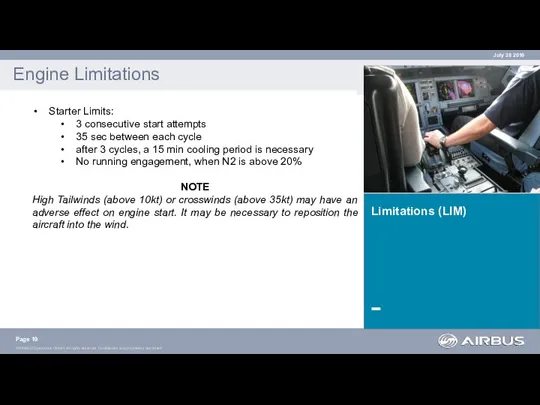
- 19. Limitations (LIM) Engine Limitations Page Starter Limits: 3 consecutive start attempts 35 sec between each cycle
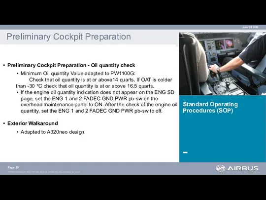
- 20. Standard Operating Procedures (SOP) Preliminary Cockpit Preparation Preliminary Cockpit Preparation - Oil quantity check Minimum Oil
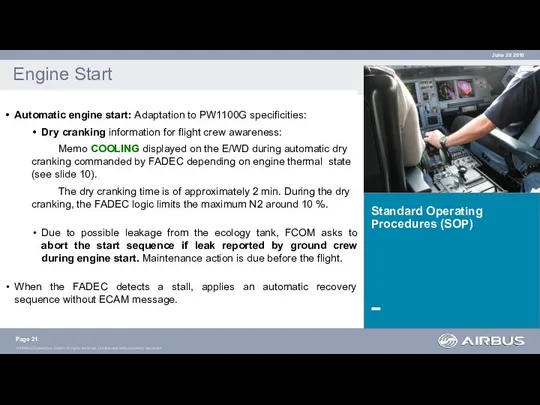
- 21. Standard Operating Procedures (SOP) Engine Start Automatic engine start: Adaptation to PW1100G specificities: Dry cranking information
- 22. Standard Operating Procedures (SOP) Engine Start – Dual Cooling Page June 28 2016
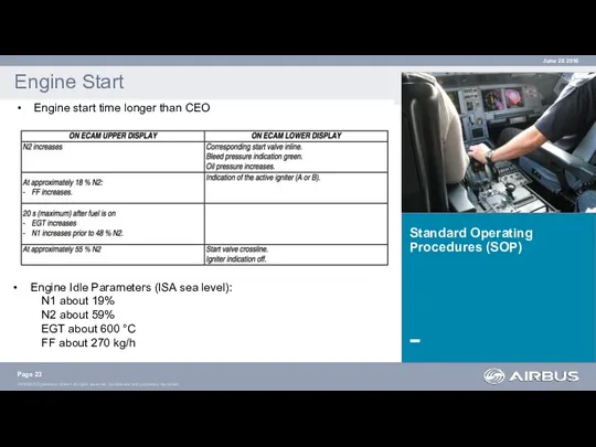
- 23. Standard Operating Procedures (SOP) Engine Start Engine start time longer than CEO Page June 28 2016
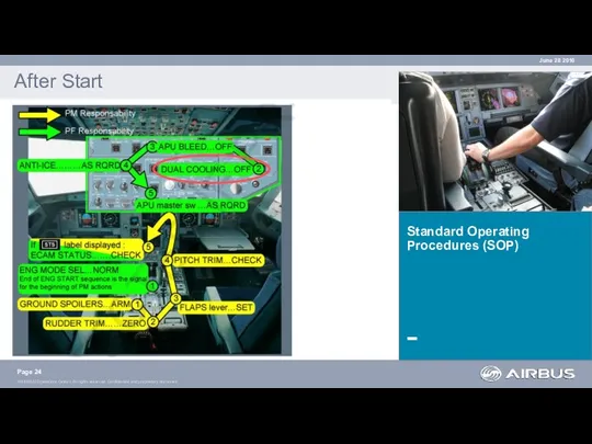
- 24. Standard Operating Procedures (SOP) After Start Page June 28 2016
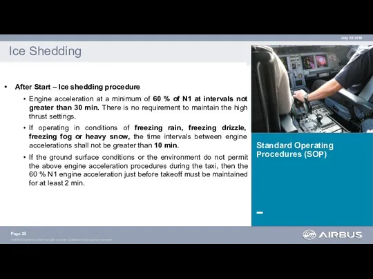
- 25. Standard Operating Procedures (SOP) Ice Shedding After Start – Ice shedding procedure Engine acceleration at a
- 26. Standard Operating Procedures (SOP) Parking Parking Caution note about brake vibrations The cooling period of 3
- 27. Supplementary Procedures SUP-70 Power Plant SUP-70 Power Plant Effect of the dry cranking function addressed in
- 28. Supplementary Procedures SUP-93 Green Operating Procedures SUP-93 GOP Single Engine Taxi-Out : XBLEED remains closed to
- 29. Abnormal Procedures (ABN) Abnormal Procedures New set of ECAM alerts due to enhanced monitoring of the
- 30. Minimum Equipment List Dispatch Update of A320 MEL Start Valve is a now “NO GO” item
- 31. Performance Page TOW around 3t more than CEO when performance limited. Higher thrust (3% to 7%
- 32. ATA 70. Powerplant ATA 30. Nacelle Anti-Ice (NAI) ATA 36. Engine Bleed Air System (EBAS) FCOM
- 33. SOP & SUP ? No major changes ABN ? New alerts New FWC standard ATA70, ATA24,
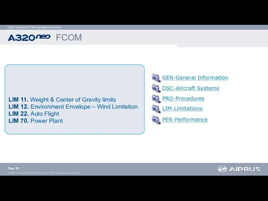
- 34. LIM 11. Weight & Center of Gravity limits LIM 12. Environment Envelope – Wind Limitation LIM
- 35. Updated Performance tables FCOM Page
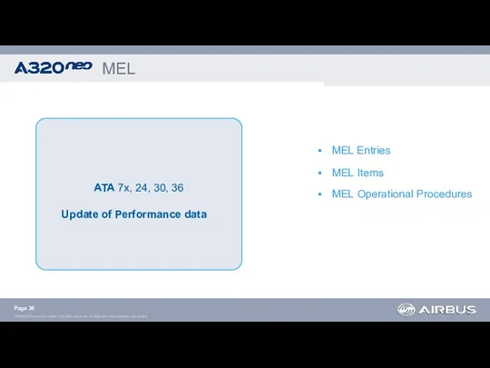
- 36. MEL ATA 7x, 24, 30, 36 Update of Performance data MEL Entries MEL Items MEL Operational
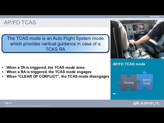
- 37. AP/FD TCAS mode AP/FD TCAS Page July 28 2016 The TCAS mode is an Auto Flight
- 38. AP/FD TCAS mode mode AP/FD TCAS When the TCAS mode arms, the FMA displays TCAS in
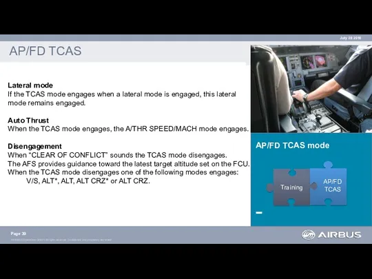
- 39. AP/FD TCAS mode AP/FD TCAS Page July 28 2016 Training AP/FD TCAS Lateral mode If the
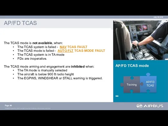
- 40. AP/FD TCAS mode AP/FD TCAS Page July 28 2016 Training AP/FD TCAS The TCAS mode is
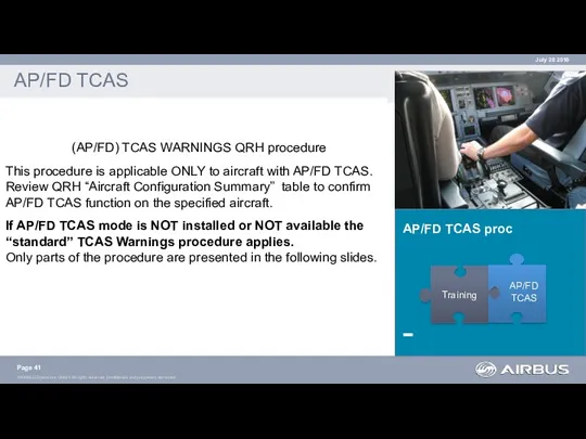
- 41. AP/FD TCAS proc AP/FD TCAS Page July 28 2016 Training AP/FD TCAS (AP/FD) TCAS WARNINGS QRH
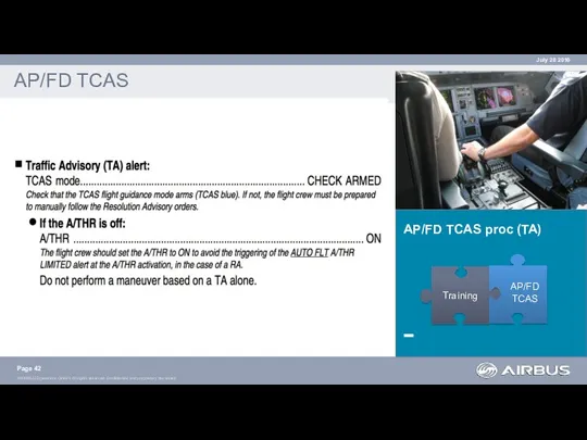
- 42. AP/FD TCAS proc (TA) AP/FD TCAS Page July 28 2016 Training AP/FD TCAS
- 43. AP/FD TCAS proc (RA) AP/FD TCAS Page July 28 2016 Training AP/FD TCAS
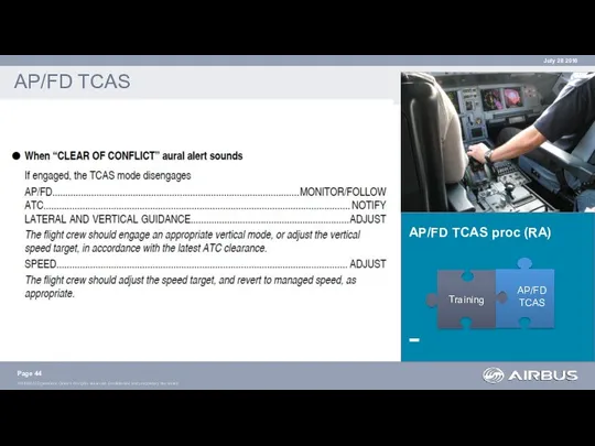
- 44. AP/FD TCAS proc (RA) AP/FD TCAS Page July 28 2016 Training AP/FD TCAS
- 45. AP/FD TCAS proc AP/FD TCAS Page July 28 2016 Training AP/FD TCAS
- 46. AP/FD TCAS proc (RA) AP/FD TCAS Page July 28 2016 Training AP/FD TCAS Refer to FCOM
- 48. Скачать презентацию
Introduction
Flight Ops Summary
Page
July 28 2016
This document provides a quick
Introduction
Flight Ops Summary
Page
July 28 2016
This document provides a quick
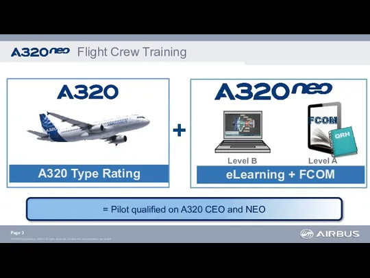
= Pilot qualified on A320 CEO and NEO
Flight Crew Training
Level B
Level
= Pilot qualified on A320 CEO and NEO
Flight Crew Training
Level B
Level
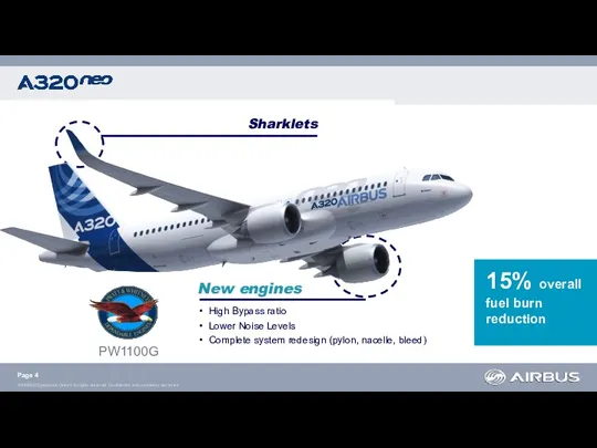
Sharklets
New engines
High Bypass ratio
Lower Noise Levels
Complete system redesign (pylon, nacelle, bleed)
Sharklets
New engines
High Bypass ratio
Lower Noise Levels
Complete system redesign (pylon, nacelle, bleed)
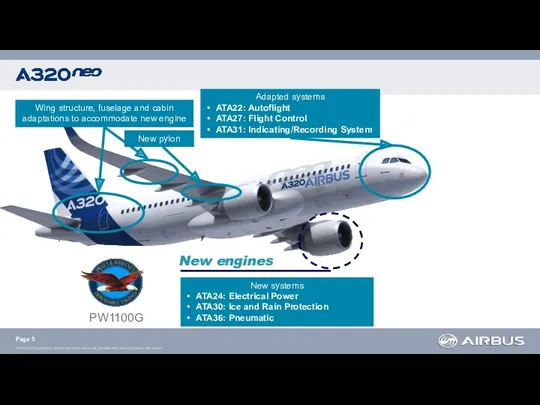
Adapted systems
ATA22: Autoflight
ATA27: Flight Control
ATA31: Indicating/Recording System
Wing structure, fuselage and
Adapted systems
ATA22: Autoflight
ATA27: Flight Control
ATA31: Indicating/Recording System
Wing structure, fuselage and
Page
Page
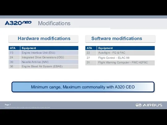
Hardware modifications
Software modifications
Page
Modifications
Minimum cange, Maximum commonality with A320 CEO
Hardware modifications
Software modifications
Page
Modifications
Minimum cange, Maximum commonality with A320 CEO
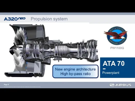
Propulsion system
Powerplant
New engine architecture
High by-pass ratio
Page
Propulsion system
Powerplant
New engine architecture
High by-pass ratio
Page
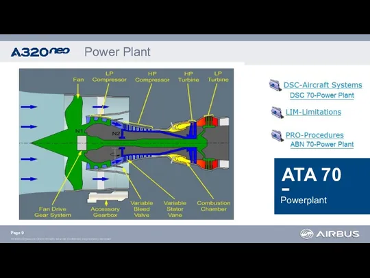
Power Plant
Powerplant
Page
Power Plant
Powerplant
Page
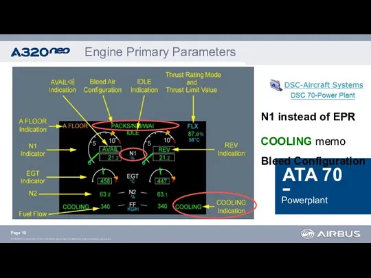
Engine Primary Parameters
Powerplant
Page
N1 instead of EPR
COOLING memo
Bleed Configuration
Engine Primary Parameters
Powerplant
Page
N1 instead of EPR
COOLING memo
Bleed Configuration
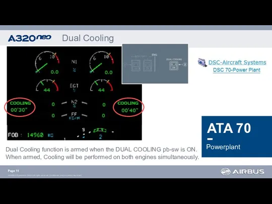
Dual Cooling
Powerplant
Page
Dual Cooling function is armed when the DUAL
Dual Cooling
Powerplant
Page
Dual Cooling function is armed when the DUAL
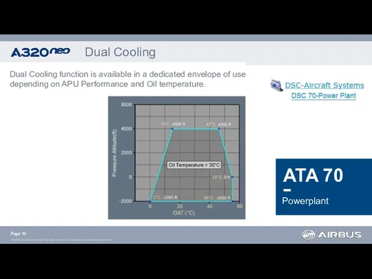
Dual Cooling
Powerplant
Page
Dual Cooling function is available in a dedicated
Dual Cooling
Powerplant
Page
Dual Cooling function is available in a dedicated
Electrical Power
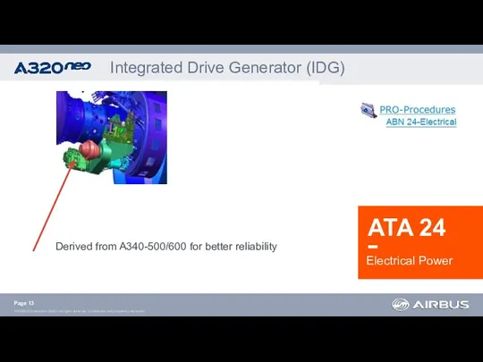
Integrated Drive Generator (IDG)
Derived from A340-500/600 for better reliability
Electrical Power
Integrated Drive Generator (IDG)
Derived from A340-500/600 for better reliability
Ice & Rain Protection
Nacelle Anti-Ice (NAI)
Two Pressure Regulated & Shut
Ice & Rain Protection
Nacelle Anti-Ice (NAI)
Two Pressure Regulated & Shut
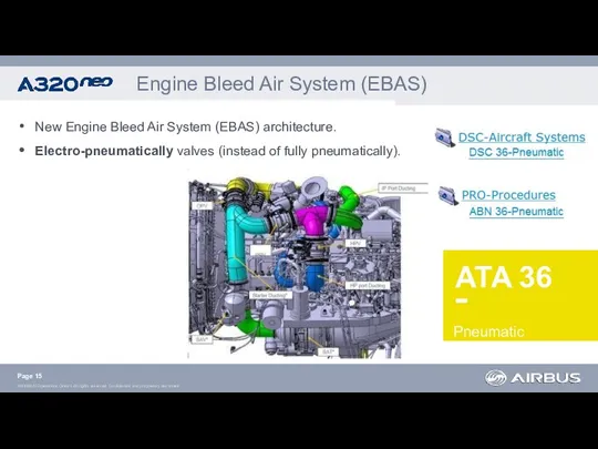
New Engine Bleed Air System (EBAS) architecture.
Electro-pneumatically valves (instead of
New Engine Bleed Air System (EBAS) architecture.
Electro-pneumatically valves (instead of
Standard Operating Procedures
(SOP)
Limitations
(LIM)
Supplementary Procedures
(SUP)
Abnormal Procedures (ABN)
Standard Operating Procedures
(SOP)
Limitations
(LIM)
Supplementary Procedures
(SUP)
Abnormal Procedures (ABN)
Limitations (LIM)
Wind and Autoland Limitations
Page
July 28 2016
Take-off crosswind limitation:
35kt
Limitations (LIM)
Wind and Autoland Limitations
Page
July 28 2016
Take-off crosswind limitation:
35kt
Limitations (LIM)
Engine Limitations
Page
Engine Limitations: Updated to take into account
Limitations (LIM)
Engine Limitations
Page
Engine Limitations: Updated to take into account
Limitations (LIM)
Engine Limitations
Page
Starter Limits:
3 consecutive start attempts
35 sec between
Limitations (LIM)
Engine Limitations
Page
Starter Limits:
3 consecutive start attempts
35 sec between
Standard Operating Procedures (SOP)
Preliminary Cockpit Preparation
Preliminary Cockpit Preparation - Oil quantity
Standard Operating Procedures (SOP)
Preliminary Cockpit Preparation
Preliminary Cockpit Preparation - Oil quantity
Standard Operating Procedures (SOP)
Engine Start
Automatic engine start: Adaptation to PW1100G specificities:
Dry
Standard Operating Procedures (SOP)
Engine Start
Automatic engine start: Adaptation to PW1100G specificities:
Dry
Standard Operating Procedures (SOP)
Engine Start – Dual Cooling
Page
June 28 2016
Standard Operating Procedures (SOP)
Engine Start – Dual Cooling
Page
June 28 2016
Standard Operating Procedures (SOP)
Engine Start
Engine start time longer than CEO
Page
Standard Operating Procedures (SOP)
Engine Start
Engine start time longer than CEO
Page
Standard Operating Procedures (SOP)
After Start
Page
June 28 2016
Standard Operating Procedures (SOP)
After Start
Page
June 28 2016
Standard Operating Procedures (SOP)
Ice Shedding
After Start – Ice shedding procedure
Engine
Standard Operating Procedures (SOP)
Ice Shedding
After Start – Ice shedding procedure
Engine
Standard Operating Procedures (SOP)
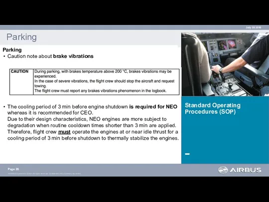
Parking
Parking
Caution note about brake vibrations
The cooling
Standard Operating Procedures (SOP)
Parking
Parking
Caution note about brake vibrations
The cooling
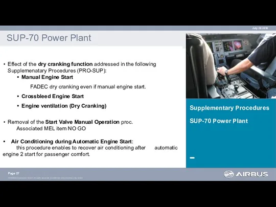
Supplementary Procedures
SUP-70 Power Plant
SUP-70 Power Plant
Effect of the dry cranking
Supplementary Procedures
SUP-70 Power Plant
SUP-70 Power Plant
Effect of the dry cranking
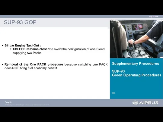
Supplementary Procedures
SUP-93
Green Operating Procedures
SUP-93 GOP
Single Engine Taxi-Out :
XBLEED remains closed
Supplementary Procedures
SUP-93
Green Operating Procedures
SUP-93 GOP
Single Engine Taxi-Out :
XBLEED remains closed
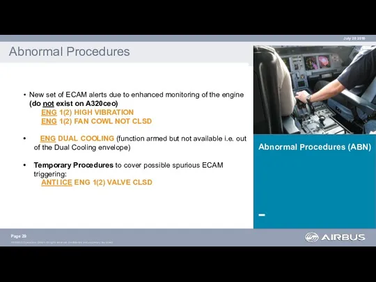
Abnormal Procedures (ABN)
Abnormal Procedures
New set of ECAM alerts due
Abnormal Procedures (ABN)
Abnormal Procedures
New set of ECAM alerts due
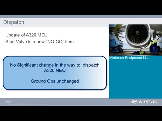
Minimum Equipment List
Dispatch
Update of A320 MEL
Start Valve is a
Minimum Equipment List
Dispatch
Update of A320 MEL
Start Valve is a
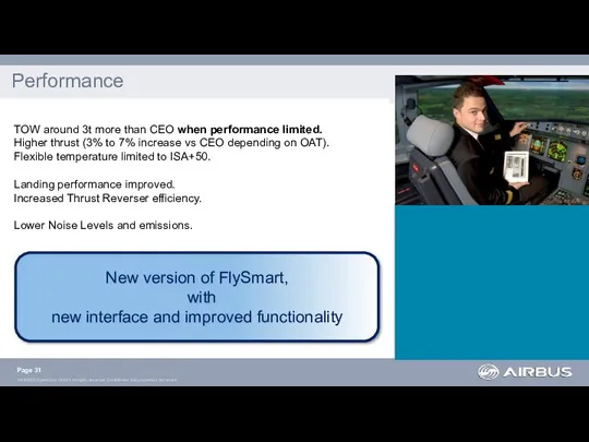
Performance
Page
TOW around 3t more than CEO when
Performance
Page
TOW around 3t more than CEO when
ATA 70. Powerplant
ATA 30. Nacelle Anti-Ice (NAI)
ATA 36. Engine Bleed Air
ATA 30. Nacelle Anti-Ice (NAI)
ATA 36. Engine Bleed Air
SOP & SUP ? No major changes
ABN ? New alerts
New FWC
ABN ? New alerts
New FWC
LIM 11. Weight & Center of Gravity limits
LIM 12. Environment
LIM 11. Weight & Center of Gravity limits
LIM 12. Environment
Updated Performance tables
FCOM
Page
Updated Performance tables
FCOM
Page
MEL
ATA 7x, 24, 30, 36
Update of Performance data
MEL Entries
MEL Items
MEL
MEL
ATA 7x, 24, 30, 36
Update of Performance data
MEL Entries
MEL Items
MEL
AP/FD TCAS mode
AP/FD TCAS
Page
July 28 2016
The TCAS mode is
AP/FD TCAS mode
AP/FD TCAS
Page
July 28 2016
The TCAS mode is
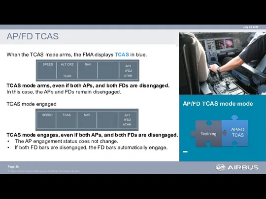
AP/FD TCAS mode mode
AP/FD TCAS
When the TCAS mode arms, the
AP/FD TCAS mode mode
AP/FD TCAS
When the TCAS mode arms, the
AP/FD TCAS mode
AP/FD TCAS
Page
July 28 2016
Training
AP/FD TCAS
Lateral mode
If the
AP/FD TCAS mode
AP/FD TCAS
Page
July 28 2016
Training
AP/FD TCAS
Lateral mode
If the
AP/FD TCAS mode
AP/FD TCAS
Page
July 28 2016
Training
AP/FD TCAS
The TCAS mode
AP/FD TCAS mode
AP/FD TCAS
Page
July 28 2016
Training
AP/FD TCAS
The TCAS mode
AP/FD TCAS proc
AP/FD TCAS
Page
July 28 2016
Training
AP/FD TCAS
(AP/FD) TCAS WARNINGS
AP/FD TCAS proc
AP/FD TCAS
Page
July 28 2016
Training
AP/FD TCAS
(AP/FD) TCAS WARNINGS
AP/FD TCAS proc (TA)
AP/FD TCAS
Page
July 28 2016
Training
AP/FD TCAS
AP/FD TCAS proc (TA)
AP/FD TCAS
Page
July 28 2016
Training
AP/FD TCAS
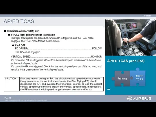
AP/FD TCAS proc (RA)
AP/FD TCAS
Page
July 28 2016
Training
AP/FD TCAS
AP/FD TCAS proc (RA)
AP/FD TCAS
Page
July 28 2016
Training
AP/FD TCAS
AP/FD TCAS proc (RA)
AP/FD TCAS
Page
July 28 2016
Training
AP/FD TCAS
AP/FD TCAS proc (RA)
AP/FD TCAS
Page
July 28 2016
Training
AP/FD TCAS
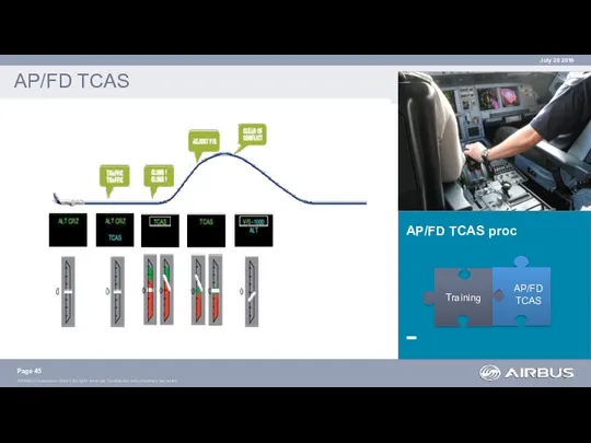
AP/FD TCAS proc
AP/FD TCAS
Page
July 28 2016
Training
AP/FD TCAS
AP/FD TCAS proc
AP/FD TCAS
Page
July 28 2016
Training
AP/FD TCAS
AP/FD TCAS proc (RA)
AP/FD TCAS
Page
July 28 2016
Training
AP/FD TCAS
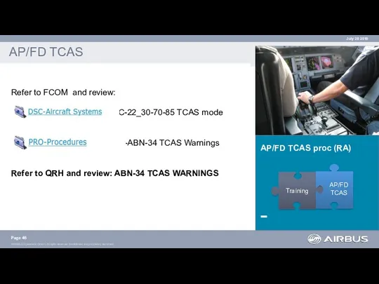
Refer to
AP/FD TCAS proc (RA)
AP/FD TCAS
Page
July 28 2016
Training
AP/FD TCAS
Refer to
 День народного единства
 Силы в механике. Виды сил в природе
 Вызовы 21-го века. Терроризм
 Творческий проект Семейный калейдоскоп
 Развитие велопешеходной инфраструктры Петрозаводского городского округа
 Особенности проведения лечебно-эвакуационных мероприятий при применении противником отравляющих веществ
 Топологические модели электронных схем. Схемы замещения электронных цепей по постоянному и переменному току
 4.Презентация к проекту
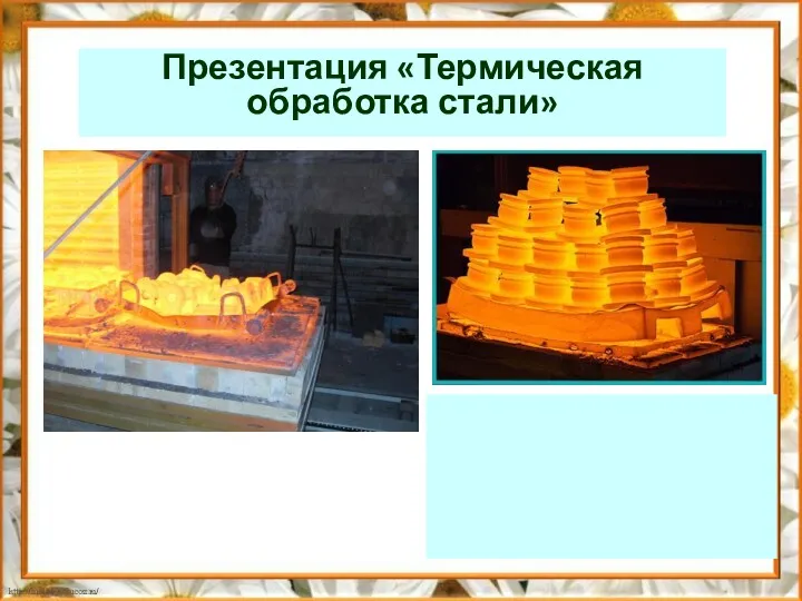 Влияние режимов термообработки на свойства сталей
 Путешествие по стране Здоровье.
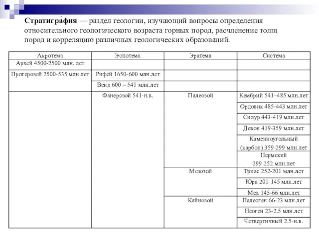 Стратигра́фия
 портфолио
 Гемофилия А, В, С. Классификация по степени тяжести
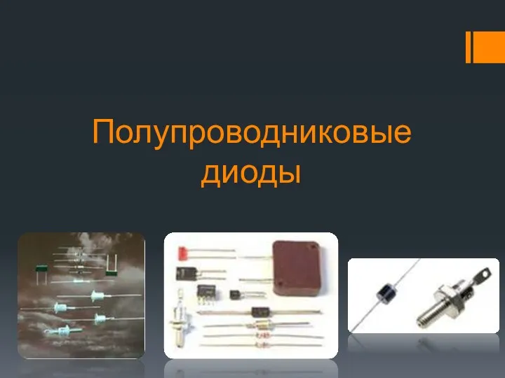 Полупроводниковые диоды. Область применения
 Структура кредитной системы и рынок ссудных капиталов
 Итоговый тест по физике
 Теории управления персоналом
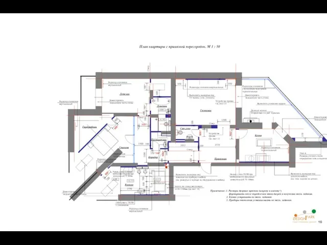 План квартиры с привязкой перегородок
 Франція. Економіко-географічна характеристика. Історико-культурні особливості
 Презентация Загадки от Деда Мороза
 Успешный руководитель
 Индия - страна чудес. (10 класс)
 Call center operator
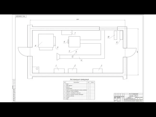 Экспериментальные исследования в лаборатории теплоаэродинамических испытаний автотракторных радиаторов
 Кто в море живет
 Предпринимательская тайна и способы ее защиты. Лекция 8
 Презентация Синяя лента апреля в МБО УСОШ № 3
 Физико-химические свойства нефтей и нефтепродуктов