- CV3663BH-Q32. Common problems solution

Содержание
- 3. In stand-by condition, Check pin 5,6 of TP20, Whether got 12V? Normal booting Whether power chip
- 4. Black screen Whether the voltage that power panel supply to Inverter is normal? Check the socket
- 5. No sound If there is any audio signal input or Whether amplifier power supply is normal?
- 6. TV no searching /no image Picture 4 T2+T+C Function unit (ATV/DTV video broke down) Check whether
- 7. TV no searching /no image Picture 5 S2 Function unit (DTV video broke down) Check whether
- 8. TV no sound, only picture Whether there is sound under PC AV? N Y Refer to
- 9. Under PC Image not in the middle Miss color, Color cast Image shakes No signal Carry
- 11. Скачать презентацию
 Электронное портфолио
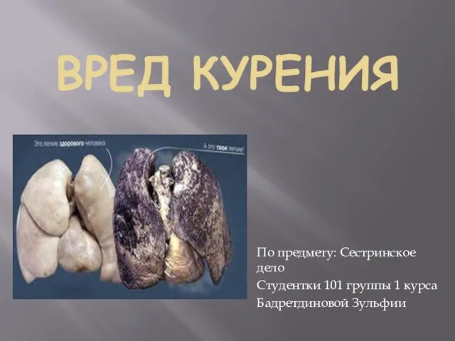 Вред курения
 Foresight Maturity Model
 Благоустройство площади для проведения массовых мероприятий в микрорайоне Каринторф (улица Краева)
 Галогены. История открытия галогенов
 Dispersions (Petroleum Disperse Systems)
 Ленинград. Блокада. Память. Книжная выставка
 Вред и польза компьютерных игр
 Моя семья
 Презентация Мастер-класс. Веселые ладошки
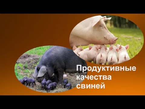 Продуктивные качества свиней
 Школа здоровья для беременных. Занятие 6
 презентация Службы района
 Измерительные трансформаторы тока
 Болезнь Виллебранда у детей
 Керамические материалы. Стекло и материалы на основе стекла
 Astana Economic Forum Global Challenges Summit
 Электронный журнал Диск
 Лазеры. (Лекция 7б)
 презентация к элективному занятию по теме Элементы комбинаторики (правило суммы и произведения)
 Подготовка к ГИА по математике. Задания 12
 Турнир Знатоков
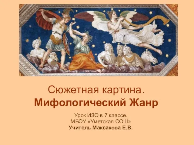 Сюжетная картина. Мифологический Жанр. Урок ИЗО в 7 классе
 Проблемы реализации принципа презумпции невиновности на досудебных стадиях
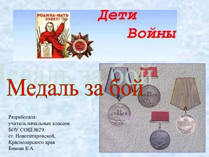 Внеклассное мероприятие Дети и война
 ООО Российские технологии качества
 Крупнейшие ГЭС России
 Консультация для воспитателей Игровые личностно - ориентированные технологии построения педагогического процесса