- Engine Components and Operation

Содержание
- 2. Objectives Explain the basic function of an internal combustion engine. Describe the five events required for
- 3. Internal Combustion Engine Function - Converts potential chemical energy in fuel into heat energy then to
- 4. Requirements for I.C. Engine Operation All Internal combustion engines must carry out five events: Air-fuel mixture
- 5. Historical Development of the I.C. Engine 1862 -- Rochas described the basic principles essential for efficient
- 6. Engine Components and Functions
- 7. Name that Engine Part 1 2 3 4 5 6 7 8 9 10 11 12
- 8. Name that Engine Part Name that Engine Part
- 9. Engine Parts ID Scoring 14 - 15 correct – Master Gearhead 12-13 – Gearhead 10 -11
- 10. Cylinder Block “Backbone” of the engine. Supports / aligns most other components. Part of basic tractor
- 11. Cylinders Cylindrical holes in which the pistons reciprocate. May be: Enblock Liners Wet liners Dry liners
- 12. Checking Cylinder Condition During engine overhaul, cylinder is checked for: Excessive wear (oversize) Out-of Round Taper
- 13. Bearings and Journals Bearing – Stationary (non-rotating) surfaces providing support to moving (rotating) component. Main bearings
- 14. Cylinder Head Seals the “top-end” of the combustion chamber. Contains the valves and the intake and
- 15. Valve Train Controls flow into and out of the combustion chamber. Time and Duration Tractor engines
- 16. Camshaft Open the intake and exhaust valves at correct time and for correct duration. Driven by
- 17. Valves Each cylinder will have: Intake valve Exhaust valve Valve nomenclature Head Margin Face Tulip Stem
- 18. Piston and Rings Piston Forms the “moveable bottom’ of the combustion chamber. Iron alloy or aluminum
- 19. Know Your Piston!
- 20. Connecting rod Connects the piston to the crankshaft Converts reciprocating piston motion to rotary motion at
- 21. Crankshaft Works with connecting rod to change reciprocating to rotary motion. Transmits mechanical energy from the
- 22. Cylinder Bore Bore is the diameter of the cylinder
- 23. Stroke Linear distance piston travels from Top Dead Center (TDC) to Bottom Dead Center (BDC).
- 24. Piston and Engine Displacement Pd = (B2 x pi x s) / 4 Ed = [(B2
- 25. Compression Ratio Ratio of “Total Volume” in cylinder at BDC to TDC. C.R. = (Pd +
- 26. Compression Ratio and Gasoline Octane Rating CR Octane Rating 5:1 73 6:1 81 7:1 87 8:1
- 27. Compression Ratio and Theoretical Otto Cycle Efficiency
- 28. 4-Stroke Cycle Engine Operation 4-stroke cycle engines require four strokes of the piston to complete the
- 29. 4-Stroke Cycle Engine Operation Intake Stroke Intake valve open. Piston moves down (TDC to BDC) in
- 30. 4-Stroke Cycle Engine Operation Compression Stroke Both valves closed. Piston moves from BDC to TDC Air
- 31. 4-Stroke Cycle Engine Operation Power Stroke Both valves are closed Air-fuel mixture burns rapidly Expansion of
- 32. 4-Stroke Cycle Engine Operation Exhaust Stroke Piston moves from BDC to TDC. Exhaust valve is open.
- 33. 4-Stroke Cycle C.I. Engine
- 34. Comparison of 4-Stroke Cycle for C.I. And S.I. Engines
- 35. Two-Stroke Cycle Engines
- 36. Two-Stroke Cycle Engine Operation
- 38. Скачать презентацию
Objectives
Explain the basic function of an internal combustion engine.
Describe the five
Objectives
Explain the basic function of an internal combustion engine.
Describe the five
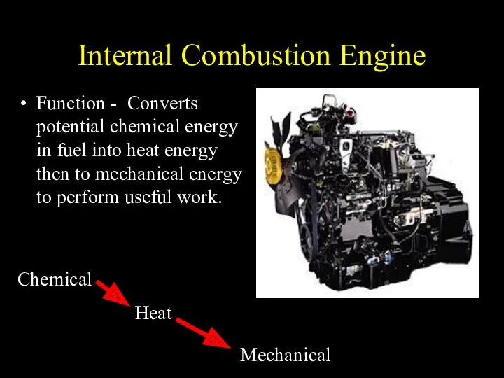
Internal Combustion Engine
Function - Converts potential chemical energy in fuel into
Internal Combustion Engine
Function - Converts potential chemical energy in fuel into
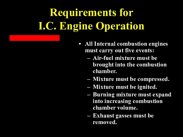
Requirements for
I.C. Engine Operation
All Internal combustion engines must carry out
Requirements for
I.C. Engine Operation
All Internal combustion engines must carry out
Historical Development
of the I.C. Engine
1862 -- Rochas described the basic
Historical Development
of the I.C. Engine
1862 -- Rochas described the basic
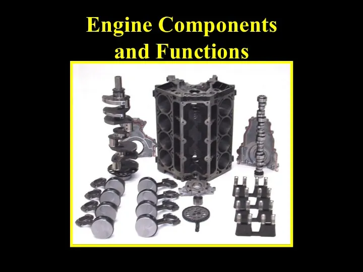
Engine Components
and Functions
Engine Components
and Functions
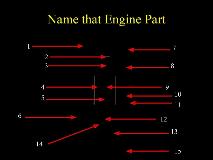
Name that Engine Part
1
2
3
4
5
6
7
8
9
10
11
12
13
14
15
Name that Engine Part
1
2
3
4
5
6
7
8
9
10
11
12
13
14
15
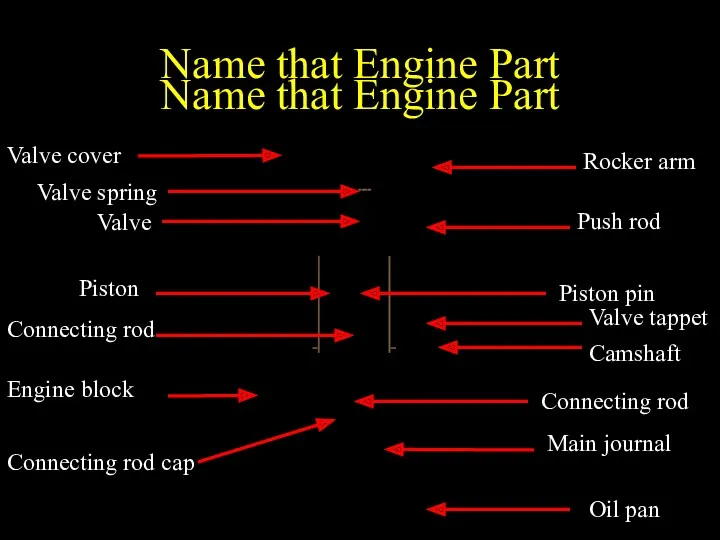
Name that Engine Part
Name that Engine Part
Name that Engine Part
Name that Engine Part
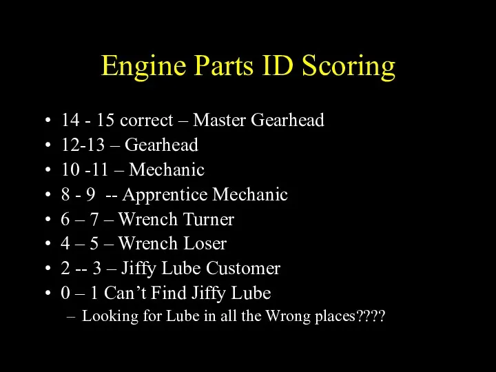
Engine Parts ID Scoring
14 - 15 correct – Master Gearhead
12-13 –
Engine Parts ID Scoring
14 - 15 correct – Master Gearhead
12-13 –
Cylinder Block
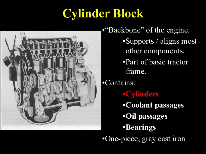
“Backbone” of the engine.
Supports / aligns most other components.
Part of
Cylinder Block
“Backbone” of the engine.
Supports / aligns most other components.
Part of
Cylinders
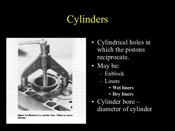
Cylindrical holes in which the pistons reciprocate.
May be:
Enblock
Liners
Wet liners
Dry liners
Cylinder
Cylinders
Cylindrical holes in which the pistons reciprocate.
May be:
Enblock
Liners
Wet liners
Dry liners
Cylinder
Checking Cylinder Condition
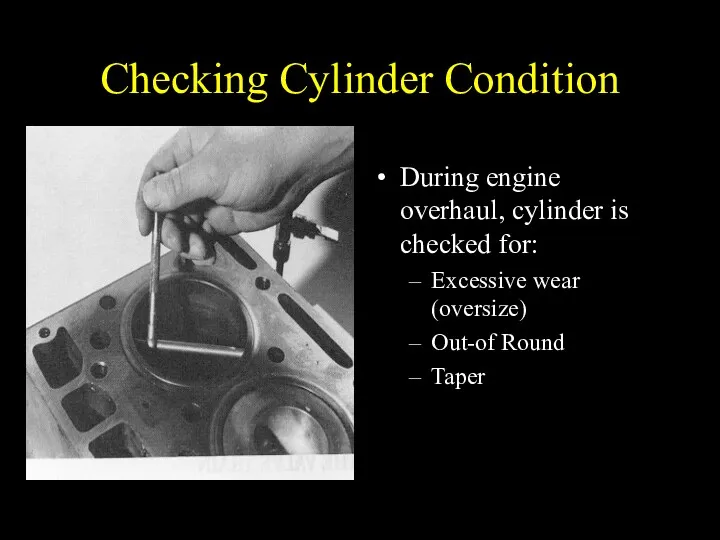
During engine overhaul, cylinder is checked for:
Excessive wear (oversize)
Out-of
Checking Cylinder Condition
During engine overhaul, cylinder is checked for:
Excessive wear (oversize)
Out-of
Bearings and Journals
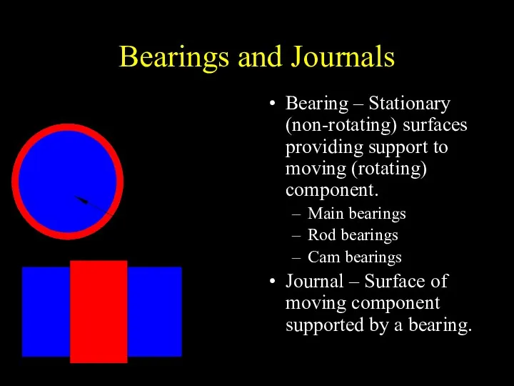
Bearing – Stationary (non-rotating) surfaces providing support to moving
Bearings and Journals
Bearing – Stationary (non-rotating) surfaces providing support to moving
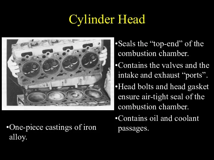
Cylinder Head
Seals the “top-end” of the combustion chamber.
Contains the valves and
Cylinder Head
Seals the “top-end” of the combustion chamber.
Contains the valves and
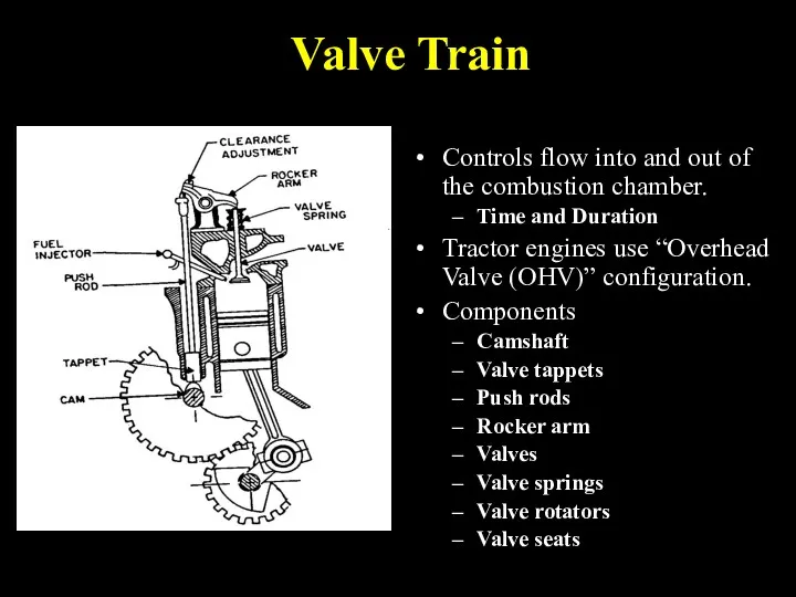
Valve Train
Controls flow into and out of the combustion chamber.
Time and
Valve Train
Controls flow into and out of the combustion chamber.
Time and
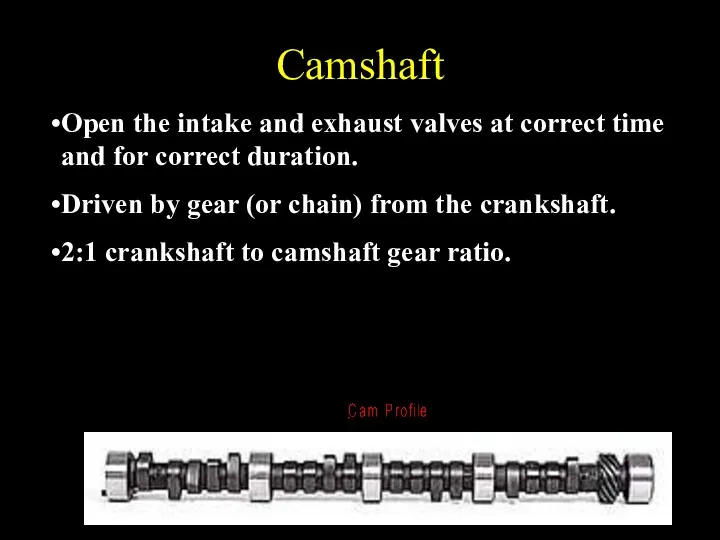
Camshaft
Open the intake and exhaust valves at correct time and for
Camshaft
Open the intake and exhaust valves at correct time and for
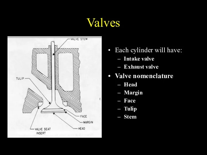
Valves
Each cylinder will have:
Intake valve
Exhaust valve
Valve nomenclature
Head
Margin
Face
Tulip
Stem
Valves
Each cylinder will have:
Intake valve
Exhaust valve
Valve nomenclature
Head
Margin
Face
Tulip
Stem
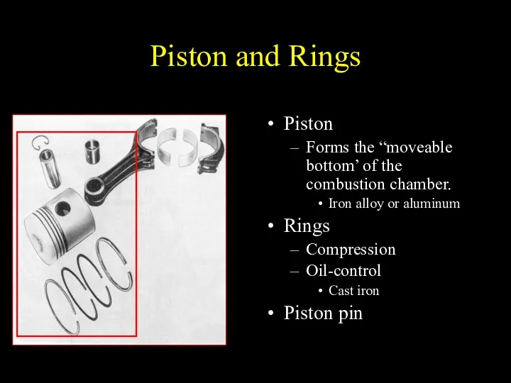
Piston and Rings
Piston
Forms the “moveable bottom’ of the combustion chamber.
Iron alloy
Piston and Rings
Piston
Forms the “moveable bottom’ of the combustion chamber.
Iron alloy
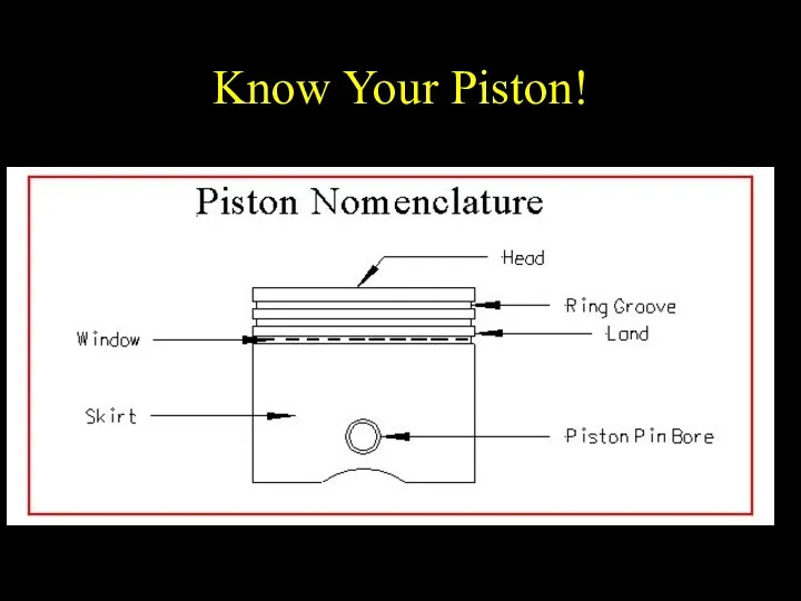
Know Your Piston!
Know Your Piston!
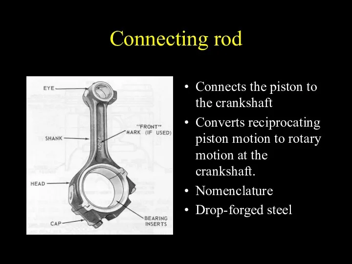
Connecting rod
Connects the piston to the crankshaft
Converts reciprocating piston motion to
Connecting rod
Connects the piston to the crankshaft
Converts reciprocating piston motion to
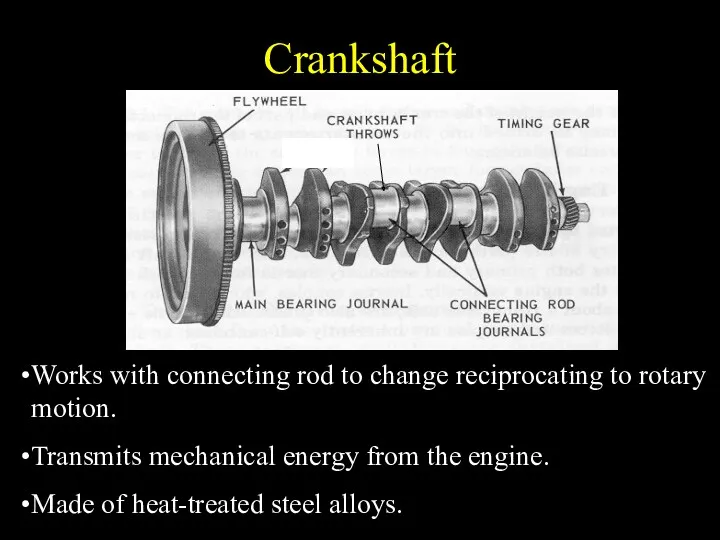
Crankshaft
Works with connecting rod to change reciprocating to rotary motion.
Transmits mechanical
Crankshaft
Works with connecting rod to change reciprocating to rotary motion.
Transmits mechanical
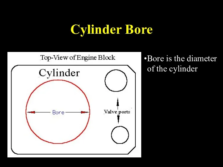
Cylinder Bore
Bore is the diameter of the cylinder
Cylinder Bore
Bore is the diameter of the cylinder
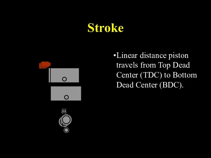
Stroke
Linear distance piston travels from Top Dead Center (TDC) to Bottom
Stroke
Linear distance piston travels from Top Dead Center (TDC) to Bottom
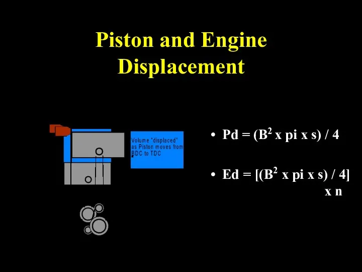
Piston and Engine Displacement
Pd = (B2 x pi x s) /
Piston and Engine Displacement
Pd = (B2 x pi x s) /
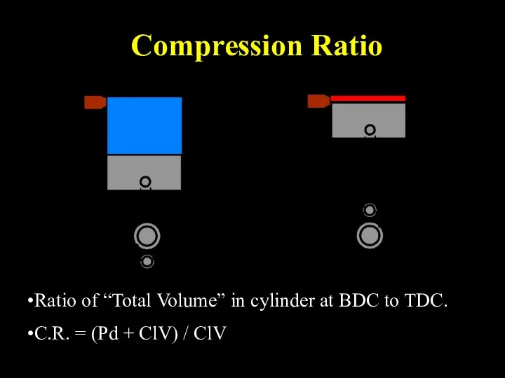
Compression Ratio
Ratio of “Total Volume” in cylinder at BDC to TDC.
C.R.
Compression Ratio
Ratio of “Total Volume” in cylinder at BDC to TDC.
C.R.
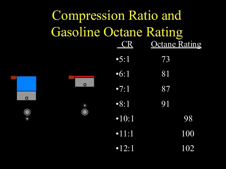
Compression Ratio and
Gasoline Octane Rating
CR Octane Rating
5:1 73
6:1 81
7:1
Compression Ratio and
Gasoline Octane Rating
CR Octane Rating
5:1 73
6:1 81
7:1
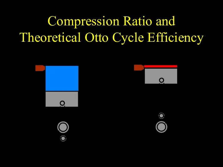
Compression Ratio and Theoretical Otto Cycle Efficiency
Compression Ratio and Theoretical Otto Cycle Efficiency
4-Stroke Cycle Engine Operation
4-stroke cycle engines require four strokes of the
4-Stroke Cycle Engine Operation
4-stroke cycle engines require four strokes of the
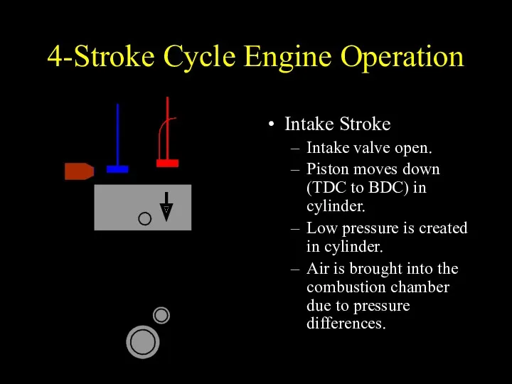
4-Stroke Cycle Engine Operation
Intake Stroke
Intake valve open.
Piston moves down (TDC to
4-Stroke Cycle Engine Operation
Intake Stroke
Intake valve open.
Piston moves down (TDC to
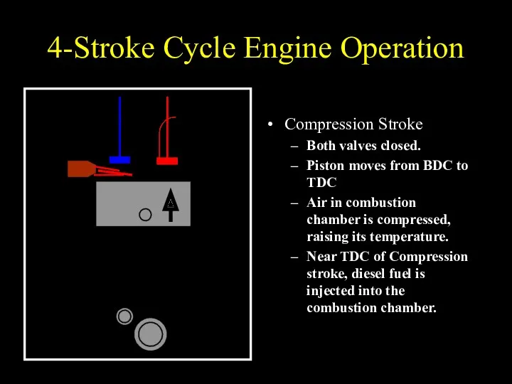
4-Stroke Cycle Engine Operation
Compression Stroke
Both valves closed.
Piston moves from BDC to
4-Stroke Cycle Engine Operation
Compression Stroke
Both valves closed.
Piston moves from BDC to
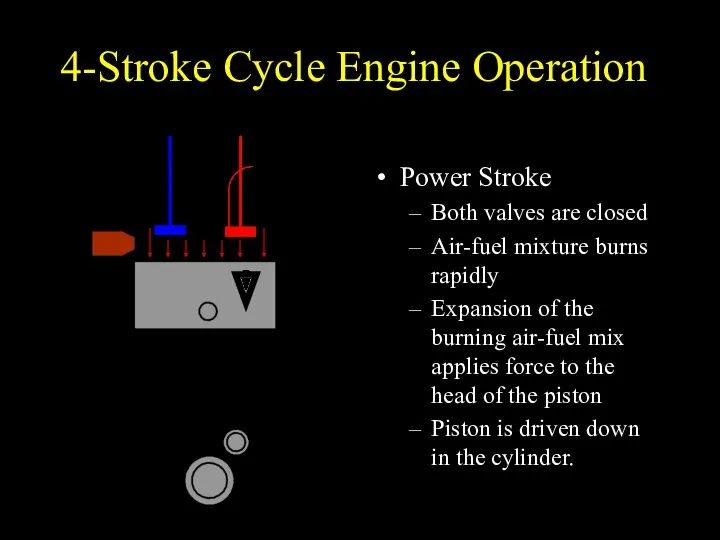
4-Stroke Cycle Engine Operation
Power Stroke
Both valves are closed
Air-fuel mixture burns rapidly
Expansion
4-Stroke Cycle Engine Operation
Power Stroke
Both valves are closed
Air-fuel mixture burns rapidly
Expansion
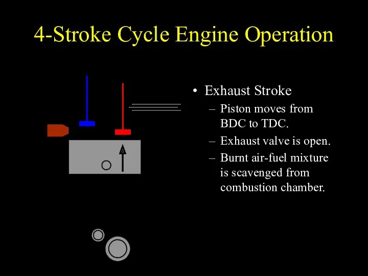
4-Stroke Cycle Engine Operation
Exhaust Stroke
Piston moves from BDC to TDC.
Exhaust valve
4-Stroke Cycle Engine Operation
Exhaust Stroke
Piston moves from BDC to TDC.
Exhaust valve
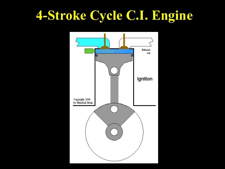
4-Stroke Cycle C.I. Engine
4-Stroke Cycle C.I. Engine
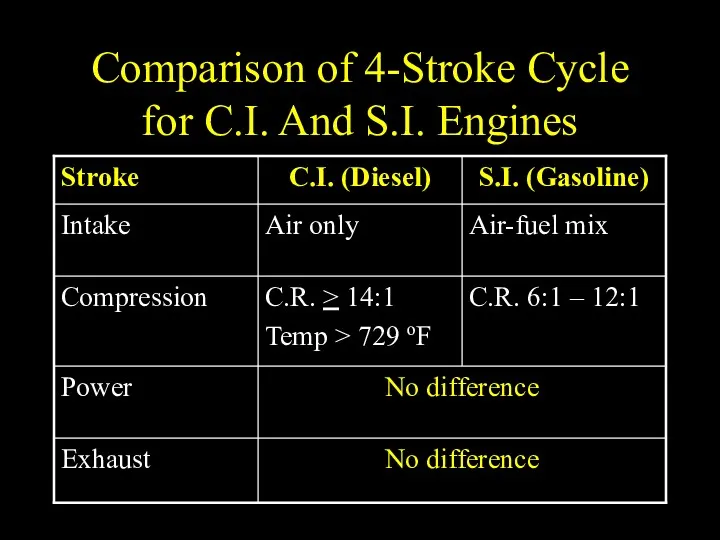
Comparison of 4-Stroke Cycle for C.I. And S.I. Engines
Comparison of 4-Stroke Cycle for C.I. And S.I. Engines
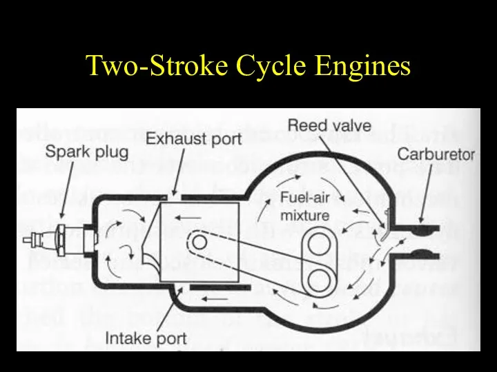
Two-Stroke Cycle Engines
Two-Stroke Cycle Engines
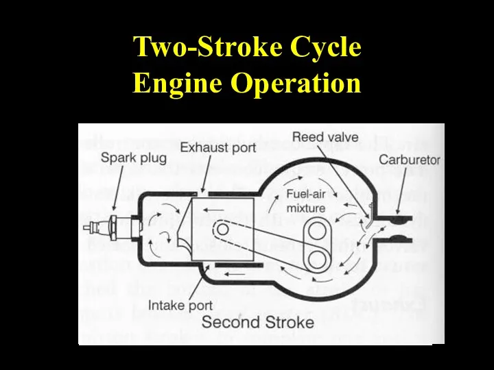
Two-Stroke Cycle
Engine Operation
Two-Stroke Cycle
Engine Operation
 Биологические науки. Интерактивный кроссворд
 ТБ на летних каникулах
 Кремнийорганикалық қосылыстар
 Арифметические и логические основы работы компьютера
 Верховино 1917-1920
 Дополнительная общеобразовательная программа Малая тимирязевка
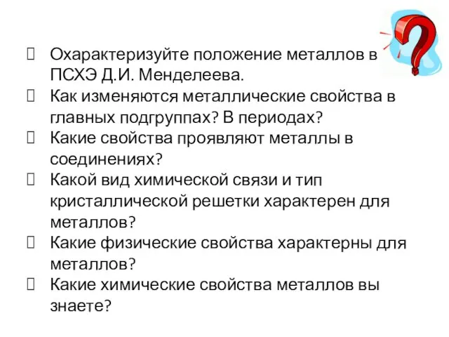 Элементы IА-группы и их соединения
 География 6 класс Изображение на плане неровностей земной поверхности
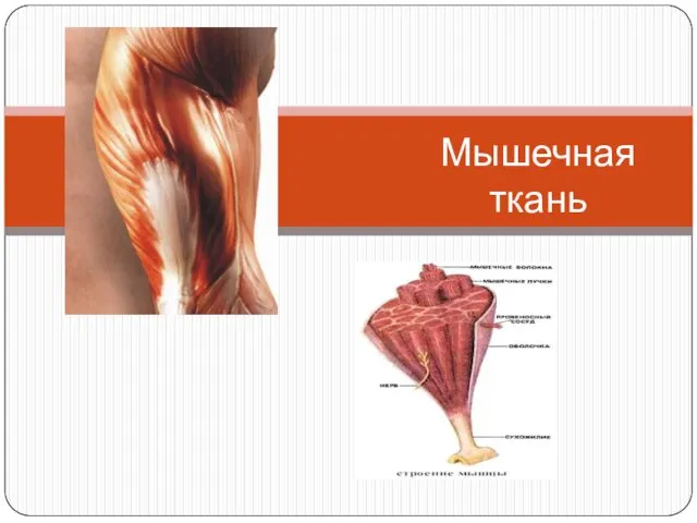 Мышечная ткань. Мышцы частей тела
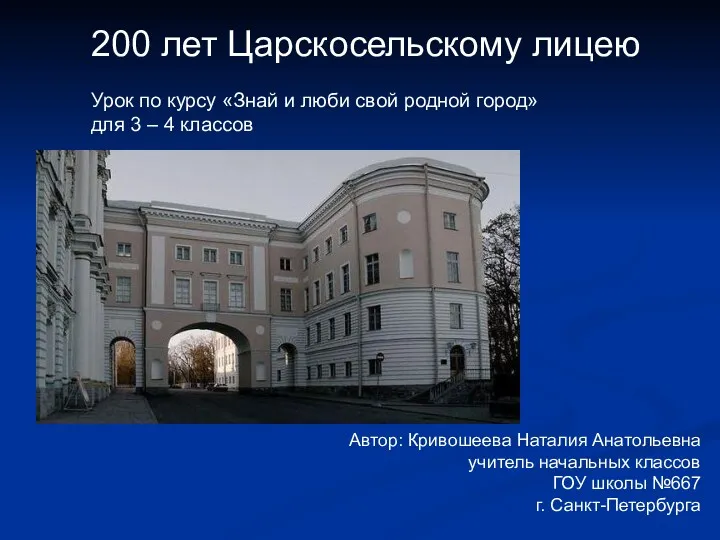 200 лет Царскосельскому лицею
 Избирательная система
 Избирательное право. Избирательные системы их виды
 Ко Дню Защитника Отечества.
 История медиа. Наскальные рисунки индейцев
 Презентация Рефлексия
 Цветная металлургия
 Осложнения в процессе бурения скважин
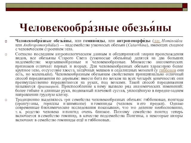 Человекообразные обезьяны
 Managementul integrat al pacienților cu diaree
 презентация на тему Метод проектов в ДОУ
 Презентация конкурса Мамочка милая, мама моя!
 Презентация Пасхальная викторина
 Проект Аты-баты, шли солдаты в подготовительной к школе группе
 Конструкции элементов полупроводниковых ИС на МДП-транзисторах
 X областной кинофестиваль для детей, юношества и семьи
 презентация по химии Техника безопасности
 Производство конструкционных материалов
 Меры безопасности при переходе железной дороги и автомобильных дорог