- Horton-Armitage. The Modular System

Содержание
- 2. The Concept The patented Modular Car Park System has been designed as a bespoke modular structure
- 3. Modular System Advantages The Modular System advantages can be summarised as follows: Off-site build Truly Modular
- 4. The Modular System Clear Span removes the use of internal columns and cross bracing, providing clear
- 5. TYPICAL COLUMN LAYOUT
- 6. The Modular System Engineering Data Design Standards The modular system is designed to various design documents
- 7. Building Regulations. The car park has been designed to comply with current Building Regulations and has
- 8. Structural problems with traditional build car parks The UK car parking industry was given an important
- 9. Ground Work Foundations- Concrete Pad Light weight super structure allows for nominal foundations Minimal ground disturbance
- 10. Ground Work Foundations - Screw Piles Innovative founding solution best described as a large self tapping
- 11. Ground Work Foundations- Ductile Iron Tube Piling . Fast effective method of forming high capacity driven
- 12. Ground Work – Social Impact Minimise loss of car parking space during construction – typical loss
- 13. Construction of ClearSpan Clear Span is suited to car parks with high movement of traffic. A
- 14. Construction phasing ClearSpan Typical 200 space car park can be erected in 5 weeks, dependent on
- 15. Exterior Cladding Design used on ClearSpan & ClearBay Designs can be tailored to client requirements and
- 16. Car Park Decking used on ClearSpan & ClearBay Highly durable yet recyclable light weight GRP decking
- 17. Ramp Solutions Ramp layout, gradient and details will be designed to suit the specific site. Typical
- 18. Panel design change Gen 1 – 3 Panels Water drained through panels to RL60 then to
- 19. Panel design change
- 20. Truss design change Gen 1 – 3 Cambered trusses
- 21. Panel make up Gen 1 – 3 Cambered trusses
- 22. Panel make up
- 23. Completed panel
- 24. Site fixed panel
- 25. Site erection
- 26. Site erection
- 27. Retail projects
- 28. Retail projects
- 29. Retail projects
- 30. Rail projects
- 32. Скачать презентацию
The Concept
The patented Modular Car Park System has been designed
The Concept
The patented Modular Car Park System has been designed
Modular System Advantages
The Modular System advantages can be summarised as follows:
Off-site
Modular System Advantages
The Modular System advantages can be summarised as follows:
Off-site
The Modular System
Clear Span removes the use of internal columns
The Modular System
Clear Span removes the use of internal columns
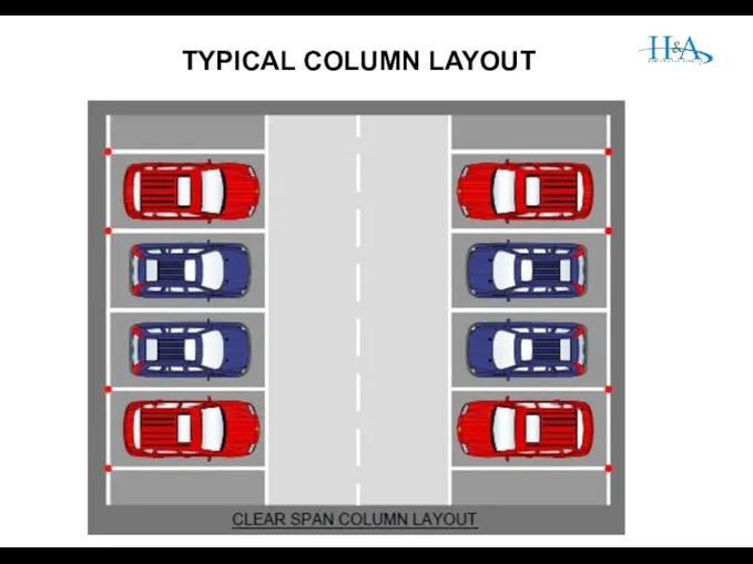
TYPICAL COLUMN LAYOUT
TYPICAL COLUMN LAYOUT
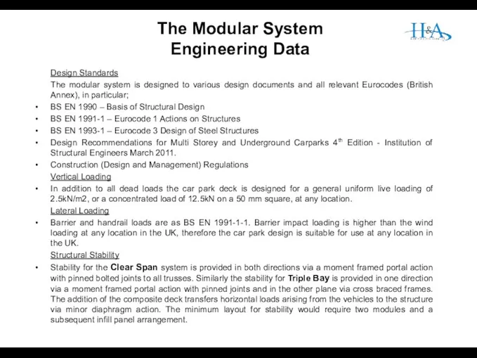
The Modular System Engineering Data
Design Standards
The modular system is designed to
The Modular System Engineering Data
Design Standards
The modular system is designed to
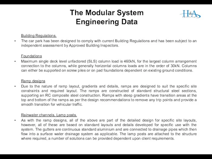
Building Regulations.
The car park has been designed to comply with current
Building Regulations.
The car park has been designed to comply with current
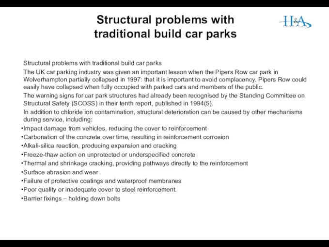
Structural problems with traditional build car parks
The UK car parking industry
Structural problems with traditional build car parks
The UK car parking industry
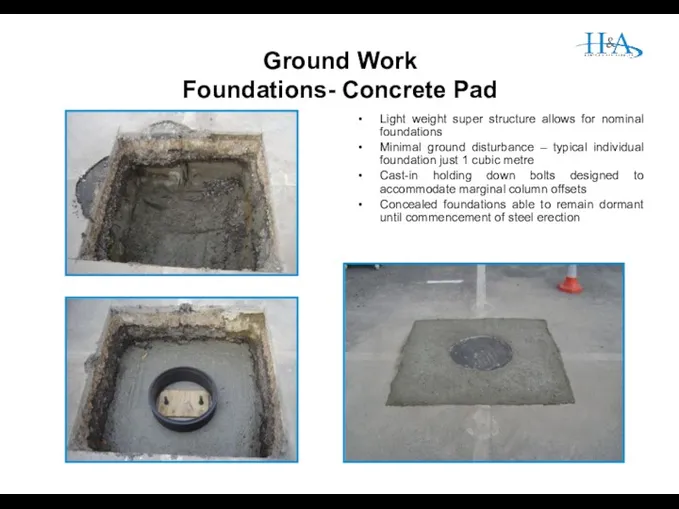
Ground Work
Foundations- Concrete Pad
Light weight super structure allows for nominal
Ground Work
Foundations- Concrete Pad
Light weight super structure allows for nominal
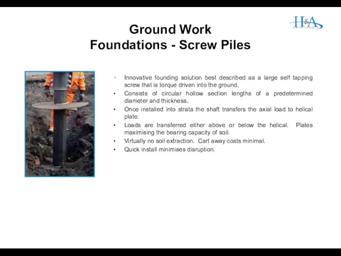
Ground Work
Foundations - Screw Piles
Innovative founding solution best described as a
Ground Work
Foundations - Screw Piles
Innovative founding solution best described as a
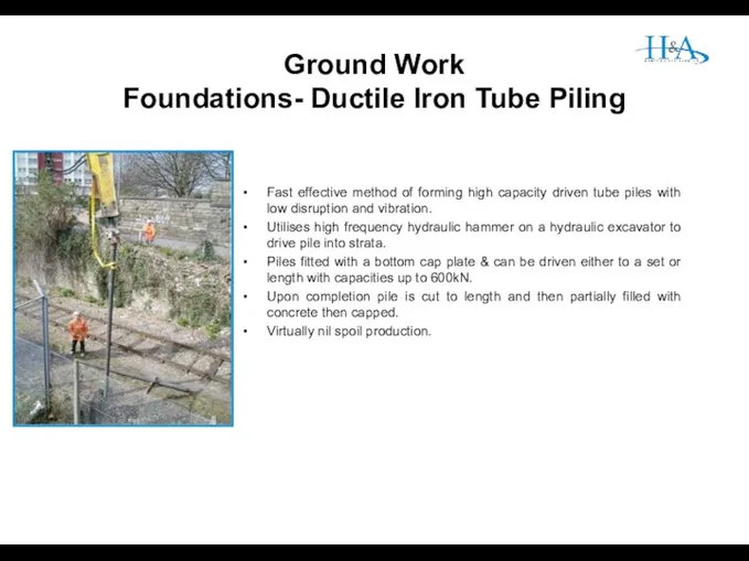
Ground Work
Foundations- Ductile Iron Tube Piling
.
Fast effective method of forming high
Ground Work
Foundations- Ductile Iron Tube Piling
.
Fast effective method of forming high
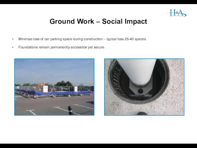
Ground Work – Social Impact
Minimise loss of car parking space during
Ground Work – Social Impact
Minimise loss of car parking space during
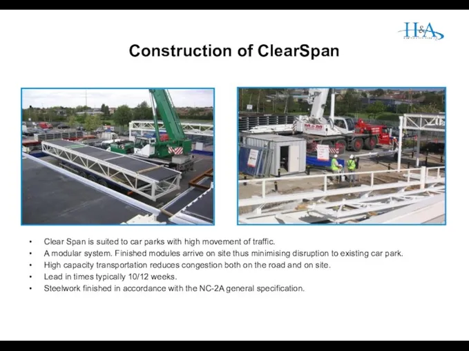
Construction of ClearSpan
Clear Span is suited to car parks with high
Construction of ClearSpan
Clear Span is suited to car parks with high
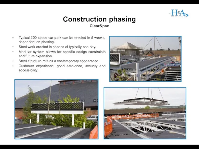
Construction phasing
ClearSpan
Typical 200 space car park can be erected in 5
Construction phasing
ClearSpan
Typical 200 space car park can be erected in 5
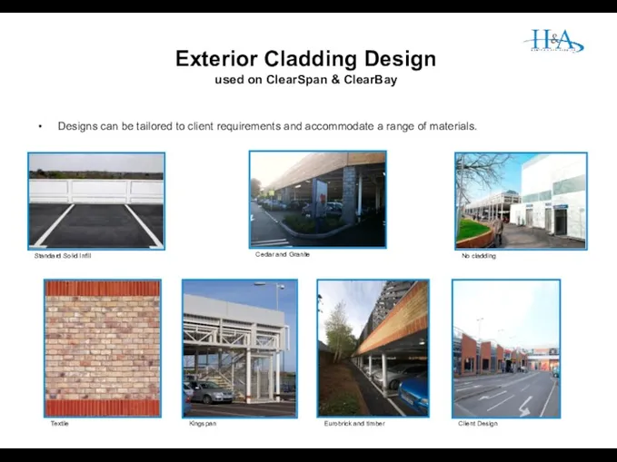
Exterior Cladding Design
used on ClearSpan & ClearBay
Designs can be tailored to
Exterior Cladding Design
used on ClearSpan & ClearBay
Designs can be tailored to
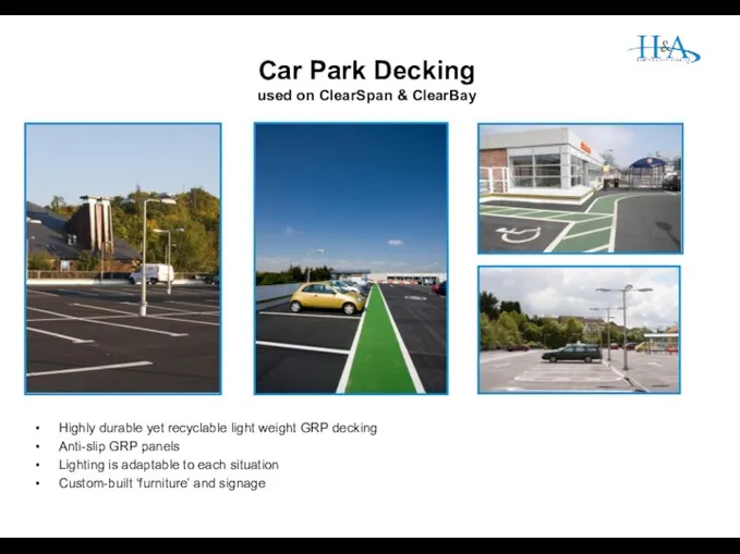
Car Park Decking
used on ClearSpan & ClearBay
Highly durable yet recyclable light
Car Park Decking
used on ClearSpan & ClearBay
Highly durable yet recyclable light
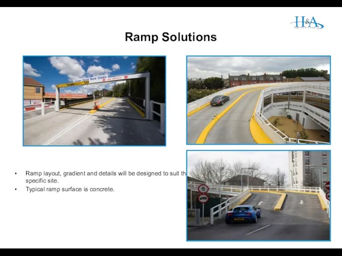
Ramp Solutions
Ramp layout, gradient and details will be designed to suit
Ramp Solutions
Ramp layout, gradient and details will be designed to suit
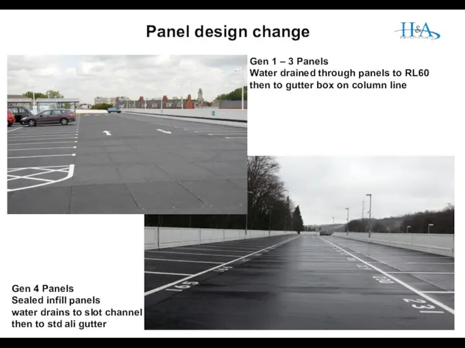
Panel design change
Gen 1 – 3 Panels
Water drained through panels
Panel design change
Gen 1 – 3 Panels
Water drained through panels
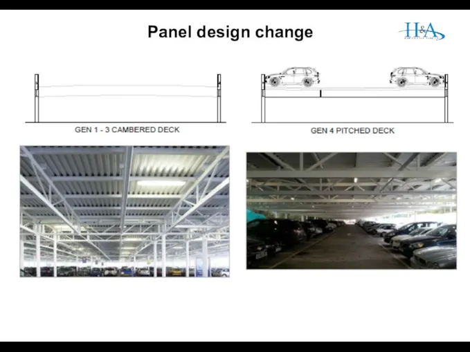
Panel design change
Panel design change
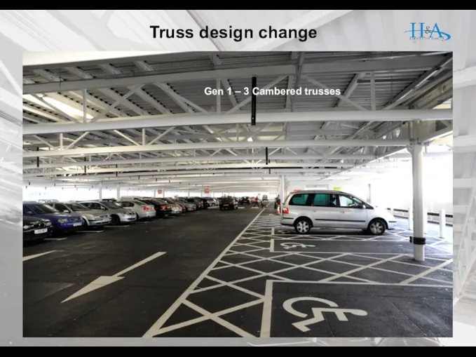
Truss design change
Gen 1 – 3 Cambered trusses
Truss design change
Gen 1 – 3 Cambered trusses
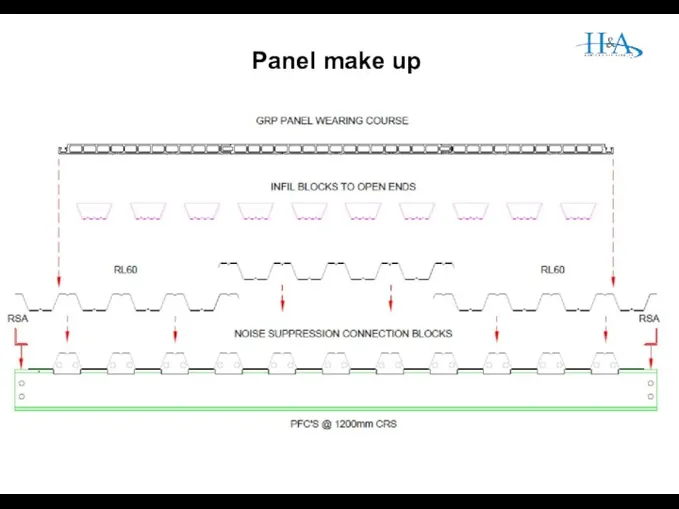
Panel make up
Gen 1 – 3 Cambered trusses
Panel make up
Gen 1 – 3 Cambered trusses
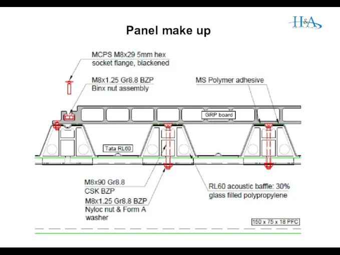
Panel make up
Panel make up
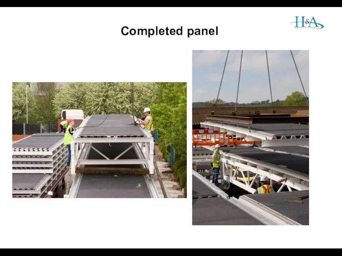
Completed panel
Completed panel
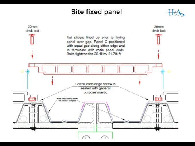
Site fixed panel
Site fixed panel
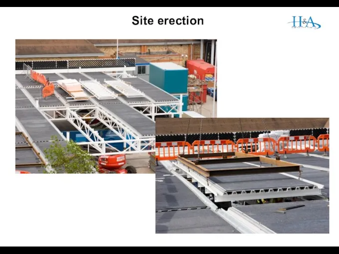
Site erection
Site erection
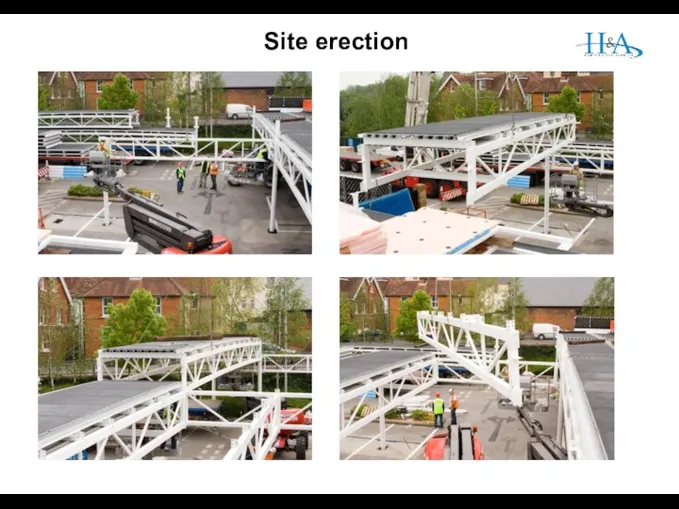
Site erection
Site erection
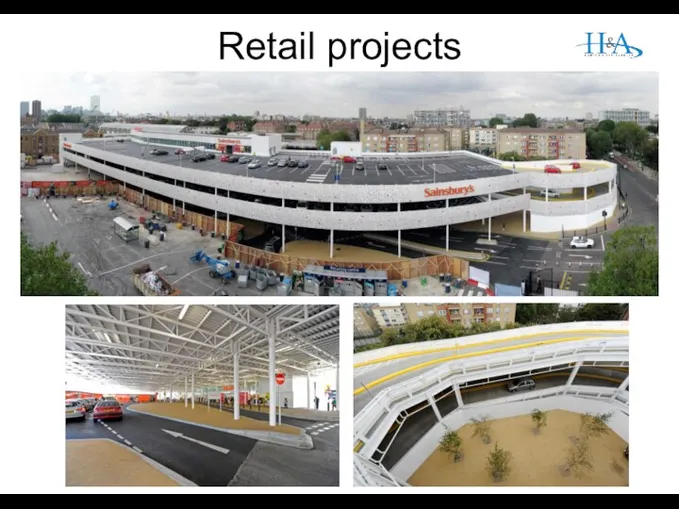
Retail projects
Retail projects
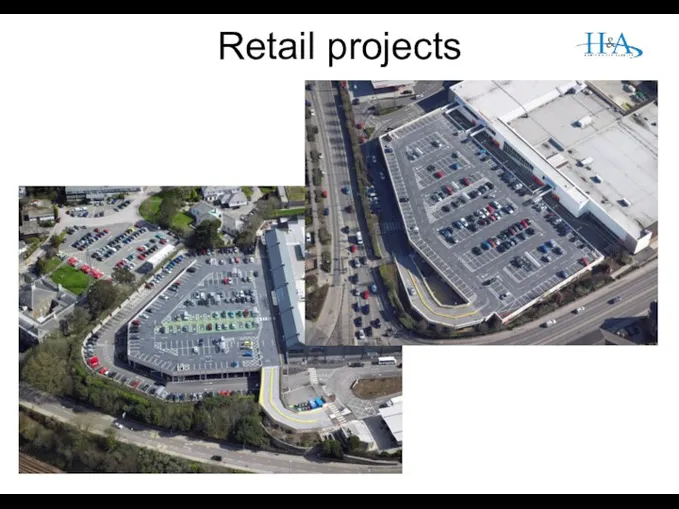
Retail projects
Retail projects
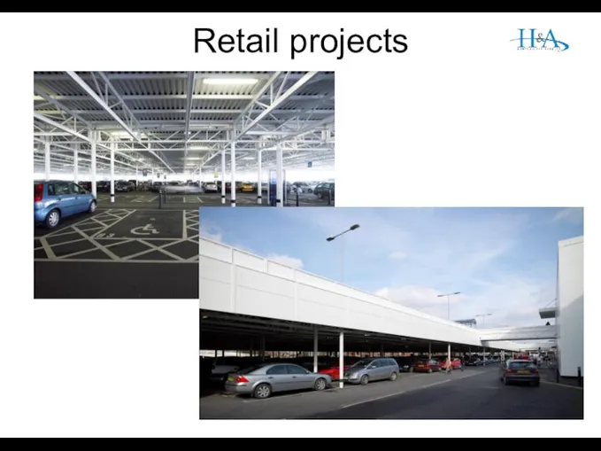
Retail projects
Retail projects
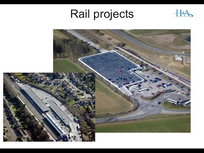
Rail projects
Rail projects
 ОСББ Наша мрія
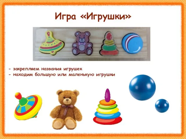 Игра игрушки для детей от 1,5 до 2,5 лет
 План в’язального цеху з виготовлення полотна, яке виготовляється на сучасних високопродуктивних машинах
 Родительское собрание Подготовка к проведению в 2014 году государственной итоговой аттестации выпускников 11-х классов
 Климат Южной Америки
 Открытый урок Сложные эфиры. Жиры.
 Дисплазия костей
 Урок-презентация по СБО Овощи и фрукты и их польза
 Технология успешного трудоустройства
 Гордость Богородского края
 Презентация к уроку географии
 Спасо-Казанский женский монастырь. Епитрахиль И.Кронштадтского
 Мороженое пломбир ГОСТ 31457-2012
 Внеклассное мероприятие Путешествие по городу Светофорск.
 В концертном зале. Московская консерватория им. П.И. Чайковского
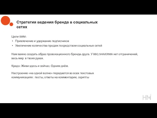 Стратегия ведения бренда в социальных сетях
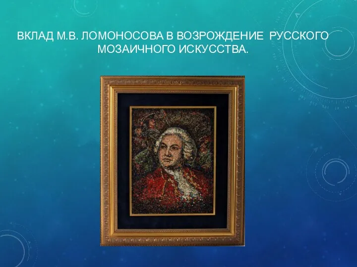 Вклад М.В. Ломоносова в возрождение русского мозаичного искусства
 Часові форми дієслів
 Русские народные ремёсла
 на тему: Развитие творческих способностей воспитанников посредства использования нетрадиционных техник изобразительного искусства
 Они ковали победу. Труженики тыла
 Образование первых государств
 История становления специальной педагогики в России
 Презентация для родителей Учебные способности ребёнка
 Правила дорожного движениядля средней группы
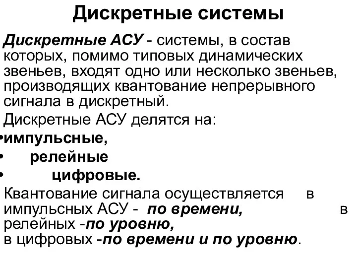 Дискретные системы
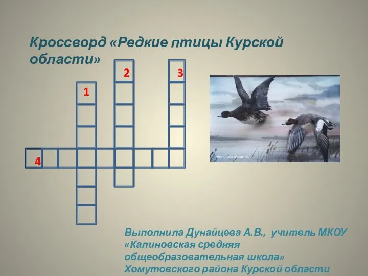 Кроссворд Редкие птицы Курской области
 Методическое портфолио победителя школьного этапа конкурса Учитель года -2015 Сибгатуллиной Р.И.