Слайд 2
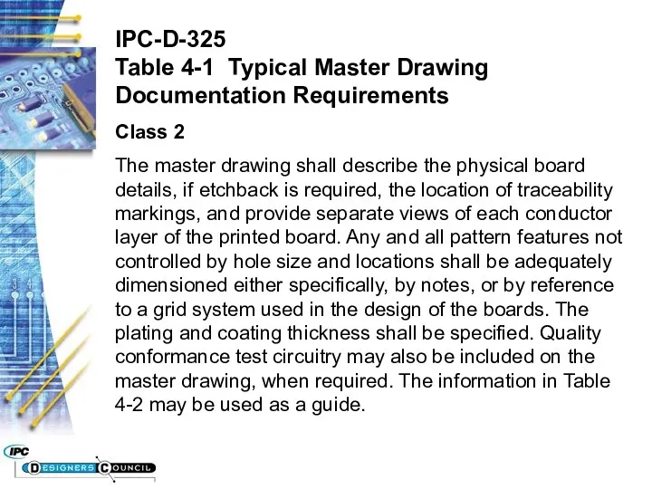
IPC-D-325
Table 4-1 Typical Master Drawing Documentation Requirements
Class 2
The master drawing shall
describe the physical board details, if etchback is required, the location of traceability markings, and provide separate views of each conductor layer of the printed board. Any and all pattern features not controlled by hole size and locations shall be adequately dimensioned either specifically, by notes, or by reference to a grid system used in the design of the boards. The plating and coating thickness shall be specified. Quality conformance test circuitry may also be included on the master drawing, when required. The information in Table 4-2 may be used as a guide.
Слайд 3
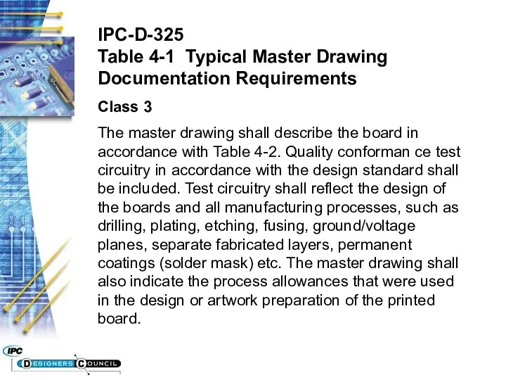
IPC-D-325
Table 4-1 Typical Master Drawing Documentation Requirements
Class 3
The master drawing shall
describe the board in accordance with Table 4-2. Quality conforman ce test circuitry in accordance with the design standard shall be included. Test circuitry shall reflect the design of the boards and all manufacturing processes, such as drilling, plating, etching, fusing, ground/voltage planes, separate fabricated layers, permanent coatings (solder mask) etc. The master drawing shall also indicate the process allowances that were used in the design or artwork preparation of the printed board.

 Нормативно-правовая база
 Образование чисел второго десятка. 1 класс
 Обучающее сочинение по картине А.К.Саврасова Грачи прилетели
 Первая оценка и как к ней относится
 Как и где зимуют птицы (1 класс)
 Макроэкономика. Макроэкономическая нестабильность: циклическое развитие экономики, инфляция, безработица. Тема 4
 Табличные информационные модели. Моделирование и формализация
 Өсімдіктердің вегетация кезеңінде синтетикалық пиретроидтарға. Жататын инсектицидтерді қолдану
 познавательные ууд
 Организация учебно- воспитательного процесса в условиях ФГОС
 Презентация занятия Осеннее дерево
 Профилактика вредных привычек
 Расстройства аффективного спектра
 Математика и наше здоровье
 9 класс.Электив. Уравнения с модулем -4.
 Фенол. 10 класс
 Системы счисления. Древние системы счисления
 Презентация Цветочные фантазии из фетра. Мастер-класс
 Высотная поясность.
 Латинская Америка в XIX – начале XX в.: время перемен
 Республика Молдова
 Географические координаты
 Порядок проведения мероприятий по надзору (контролю) сотрудниками государственного пожарного надзора
 Writing an essay (C2)
 Искусственные нейронные сети. Лекция 15-16
 Классный час Поговорим о здоровье Классный час Поговорим о здоровье. Здоровье — это здоровый образ жизни
 Заполнение бланков участников итогового сочинения (изложения)
 Дробь как одна или несколько равных долей