- LCD TV LB350-650 Training manual. Inside of New Models

Содержание
- 2. Inside of New Models
- 3. CONTENTS Introduction Inside of Models Board description Disassembly Trouble Shooting Software Relating Appendix
- 4. Introduction Best Picture Quality Simple Function, New Design Acceptable Price Support HDMI New Functions
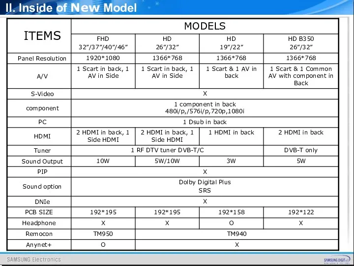
- 5. II. Inside of New Model
- 6. TM950 TM940 Remote Controller Type
- 7. B350 : HD 26”/32” CABINET ? C/Front : New Design, High Glossy ? C/Rear : Decoration,
- 8. CABINET ? C/Front : A450 ? C/Rear : New Decoration, Holder-Boss, Guide-Stand II. Inside of New
- 9. B460 HD, 32” CABINET ? C/Front : PDP B450 Design ? C/Rear , Decoration, Holder-Boss, Guide-Stand
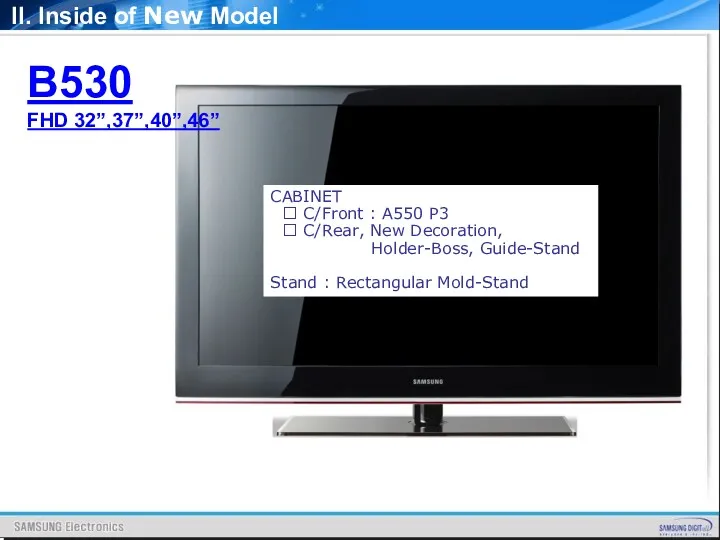
- 10. CABINET ? C/Front : A550 P3 ? C/Rear, New Decoration, Holder-Boss, Guide-Stand Stand : Rectangular Mold-Stand
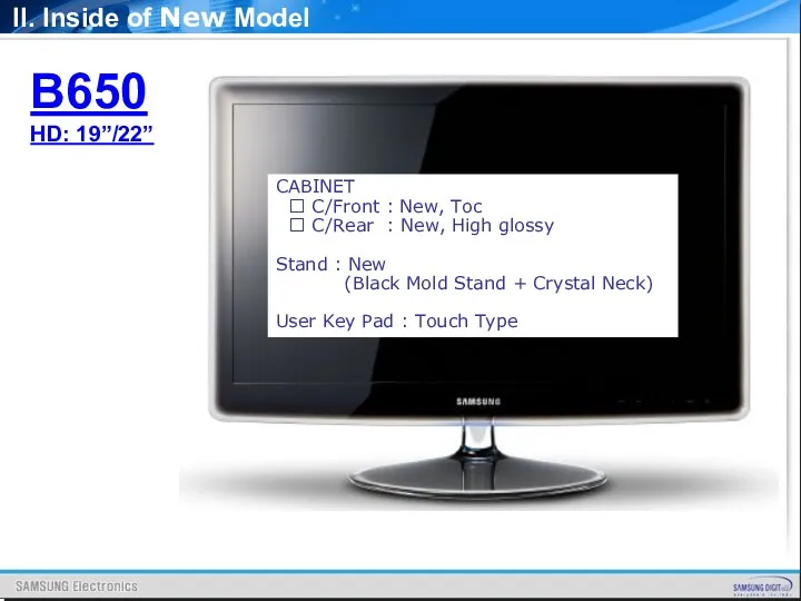
- 11. B650 HD: 19”/22” CABINET ? C/Front : New, Toc ? C/Rear : New, High glossy Stand
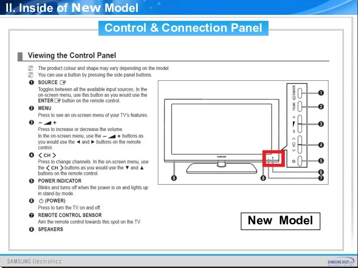
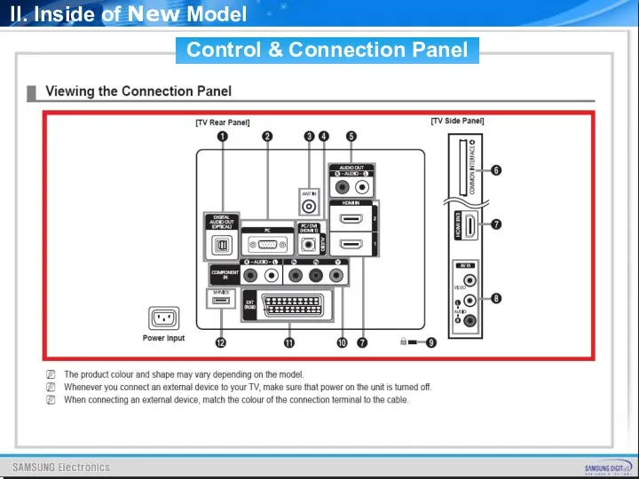
- 12. Control & Connection Panel New Model II. Inside of New Model
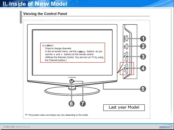
- 13. Last year Model II. Inside of New Model
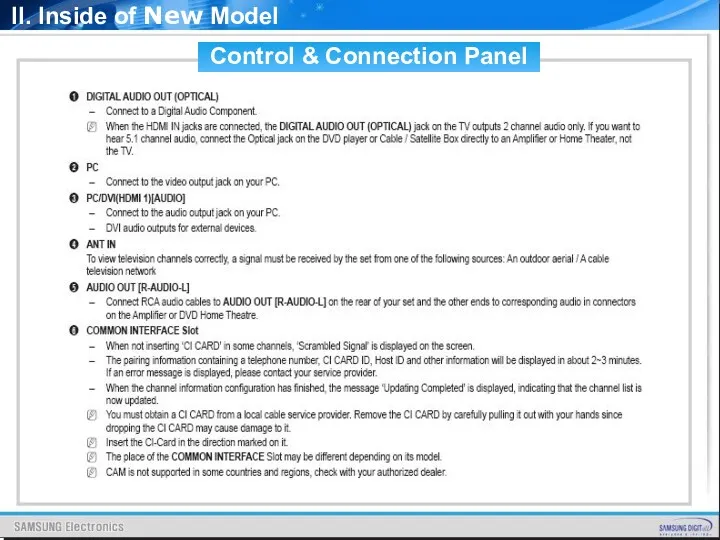
- 14. Control & Connection Panel II. Inside of New Model
- 15. Control & Connection Panel II. Inside of New Model
- 16. Control & Connection Panel II. Inside of New Model
- 17. II. Inside of New Model
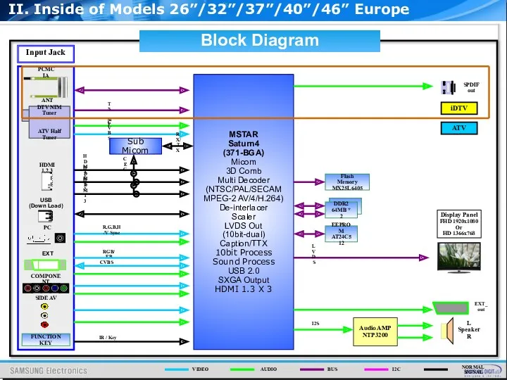
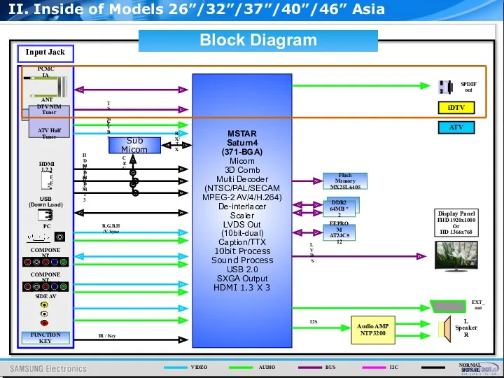
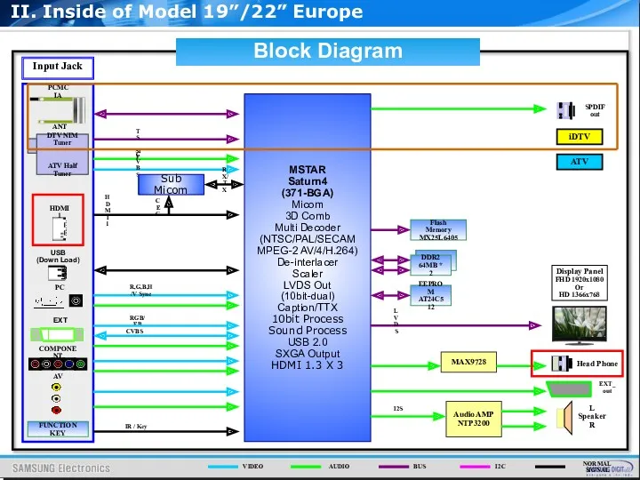
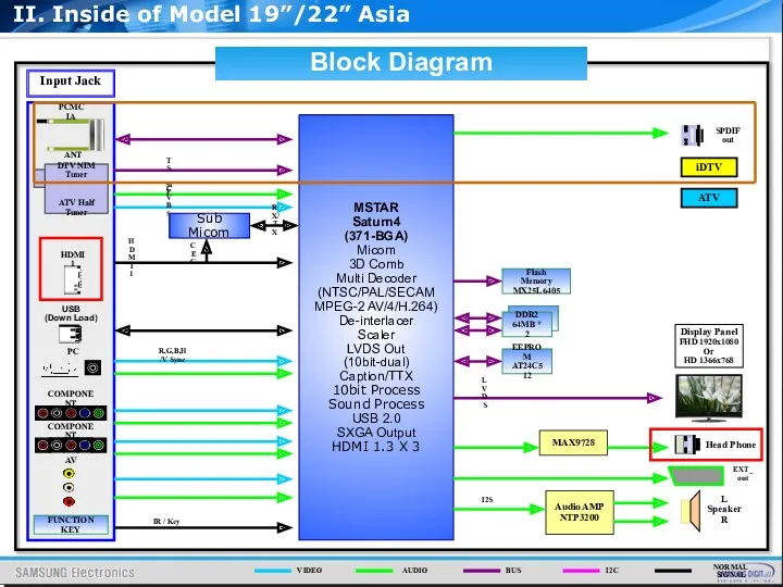
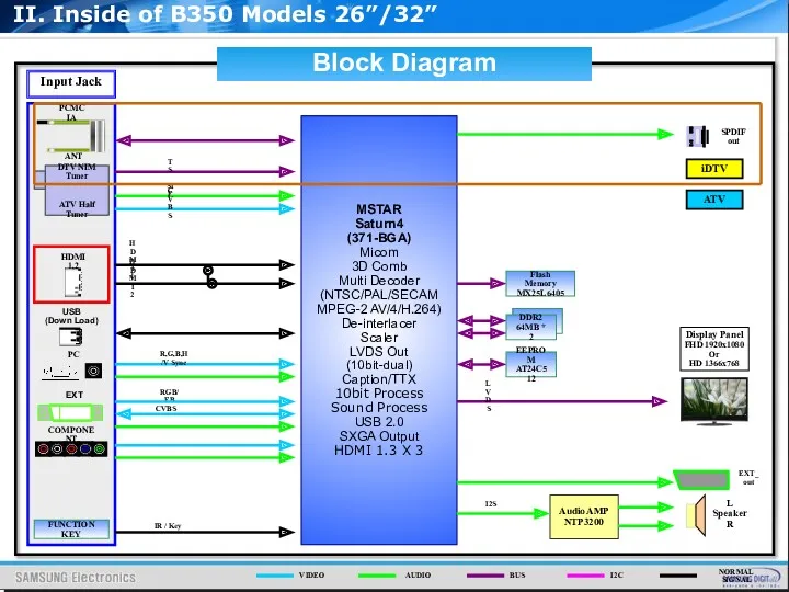
- 18. Audio AMP NTP3200 ANT Input Jack MSTAR Saturn4 (371-BGA) Micom 3D Comb Multi Decoder (NTSC/PAL/SECAM MPEG-2
- 19. Audio AMP NTP3200 ANT Input Jack MSTAR Saturn4 (371-BGA) Micom 3D Comb Multi Decoder (NTSC/PAL/SECAM MPEG-2
- 20. Audio AMP NTP3200 ANT Input Jack MSTAR Saturn4 (371-BGA) Micom 3D Comb Multi Decoder (NTSC/PAL/SECAM MPEG-2
- 21. Audio AMP NTP3200 ANT Input Jack MSTAR Saturn4 (371-BGA) Micom 3D Comb Multi Decoder (NTSC/PAL/SECAM MPEG-2
- 22. Audio AMP NTP3200 ANT Input Jack MSTAR Saturn4 (371-BGA) Micom 3D Comb Multi Decoder (NTSC/PAL/SECAM MPEG-2
- 23. IP Board, Main Board, TCON Board,Panel Inner Feature IP B’D’ MAIN B’D’ SPEAKER SPEAKER TCON B’D’
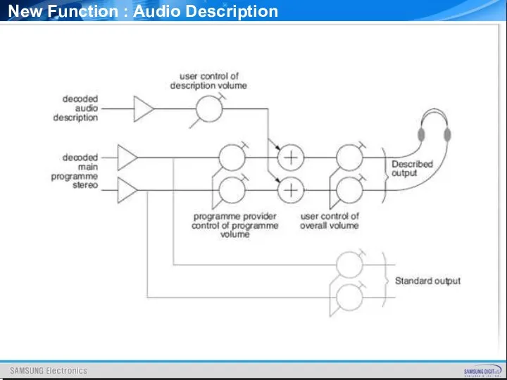
- 24. Audio description [From Wikipedia, the free encyclopedia] Audio description refers to an additional narration refers to
- 25. New Function : Audio Description
- 26. New Function : Dolby Digital Plus Audio encoding/compression Dolby Digital (also known as AC-3): is a
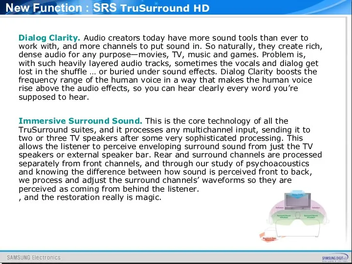
- 27. New Function : SRS TruSurround HD Dialog Clarity. Audio creators today have more sound tools than
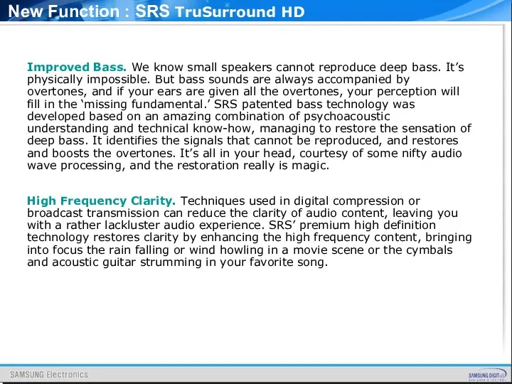
- 28. New Function : SRS TruSurround HD Improved Bass. We know small speakers cannot reproduce deep bass.
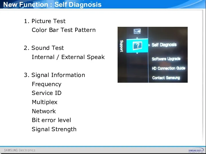
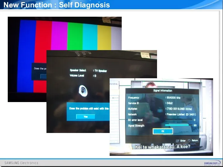
- 29. New Function : Self Diagnosis 1. Picture Test Color Bar Test Pattern 2. Sound Test Internal
- 30. New Function : Self Diagnosis
- 31. New Function : Alternative Software
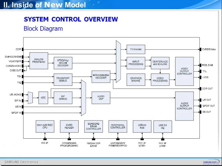
- 33. Key parts SCALER : SEMS12 SOUND AMP : NTP3200 II. Inside of New Model
- 34. SCALER: SEMS12 GENERAL DESCRIPTION The SEMS12 is a highly integrated controller IC for LCD/PDP DTV applications
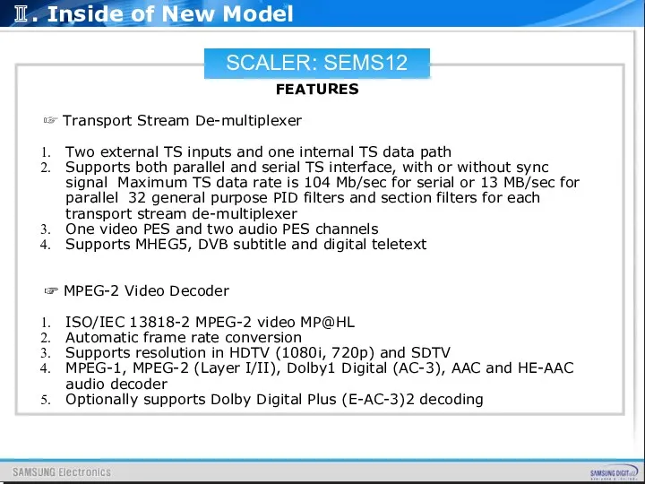
- 35. SCALER: SEMS12 FEATURES ☞ Transport Stream De-multiplexer Two external TS inputs and one internal TS data
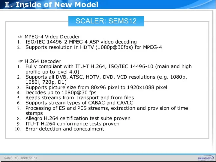
- 36. SCALER: SEMS12 ☞ MPEG-4 Video Decoder ISO/IEC 14496-2 MPEG-4 ASP video decoding Supports resolution in HDTV
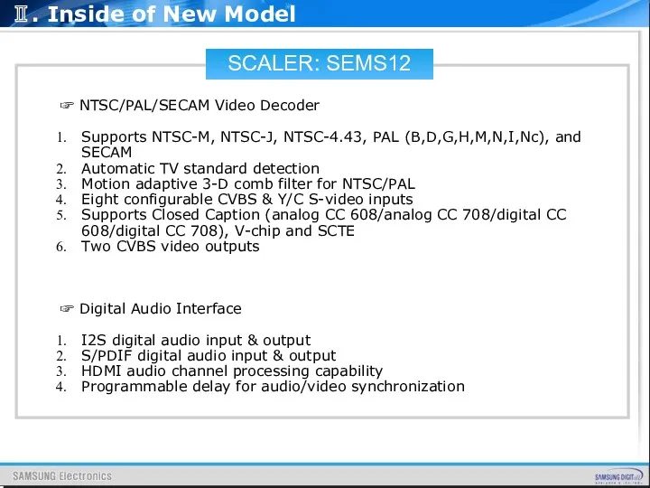
- 37. SCALER: SEMS12 ☞ NTSC/PAL/SECAM Video Decoder Supports NTSC-M, NTSC-J, NTSC-4.43, PAL (B,D,G,H,M,N,I,Nc), and SECAM Automatic TV
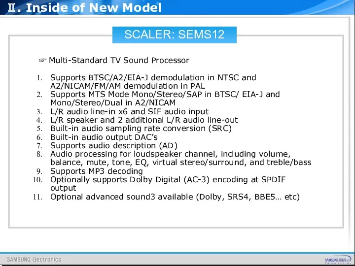
- 38. SCALER: SEMS12 ☞ Multi-Standard TV Sound Processor Supports BTSC/A2/EIA-J demodulation in NTSC and A2/NICAM/FM/AM demodulation in
- 39. SCALER: SEMS12 ☞ Analog RGB Compliant Input Ports Three analog ports support up to 1080P Supports
- 40. SCALER: SEMS12 ☞ DVI/HDCP/HDMI Compliant Input Port Three DVI/HDCP/HDMI input ports support up to 225MHz @
- 41. SCALER: SEMS12 ☞ Video Processing & Conversion 3-D motion adaptive video de-interlacers with edge-oriented adaptive algorithm
- 42. SCALER: SEMS12 ☞ Hardware JPEG Supports sequential mode, single scan Supports both color and grayscale picture
- 43. SOUND AMP:NTP3200 Features ▪ Stereo (20W ⅹ 2) ▪ Wide Supply Voltage Range (7.5V~24V) ▪ Floating
- 44. SOUND AMP:NTP3200 Description The NTP-3200 is a single chip full digital audio amplifier including power stage
- 45. SOUND AMP:NTP3200 Package 56 pin MLF 8mm by 8mm Ⅱ. Inside of New Model
- 46. SOUND AMP:NTP3200 PIN DESCRIPTIONS Ⅱ. Inside of New Model
- 47. SOUND AMP:NTP3200 PIN DESCRIPTIONS Ⅱ. Inside of New Model
- 48. SOUND AMP:NTP3200 PIN DESCRIPTIONS Ⅱ. Inside of New Model
- 49. BOARD DESCRIPTION Ⅲ. Board description
- 50. MAIN BOARD LAYOUT MAIN BOARD PIN CHARACTERISTIC IP BOARD INPUT CHARACTERISTIC POWER OUTPUT CHARACTERISTIC INVERTER OUTPUT
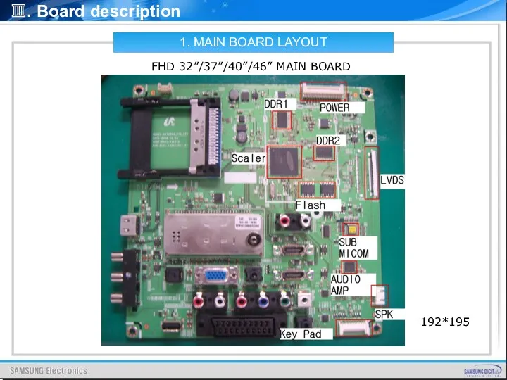
- 51. 1. MAIN BOARD LAYOUT FHD 32”/37”/40”/46” MAIN BOARD 192*195 Ⅲ. Board description
- 52. 1. MAIN BOARD LAYOUT HD 26”/32” MAIN BOARD 192*195 Mirror Ⅲ. Board description
- 53. 1. MAIN BOARD LAYOUT HD 19”/22” MAIN BOARD 192*158 Normal 9P Ⅲ. Board description Audio AMP
- 54. 1. MAIN BOARD LAYOUT HD B350 26”/32” MAIN BOARD 192*122 Mirror Ⅲ. Board description Audio AMP
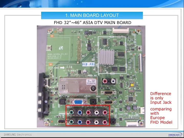
- 55. 1. MAIN BOARD LAYOUT FHD 32”~46” ASIA DTV MAIN BOARD Difference is only Input Jack comparing
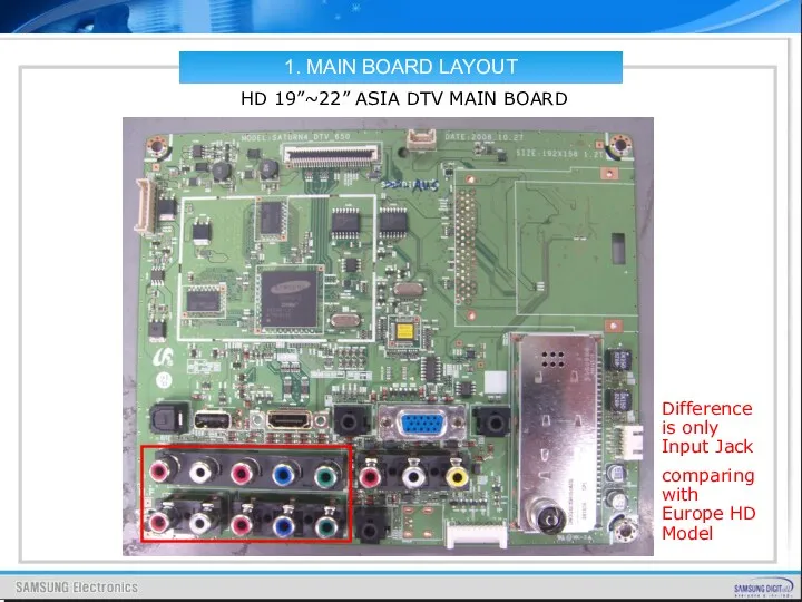
- 56. 1. MAIN BOARD LAYOUT HD 19”~22” ASIA DTV MAIN BOARD Difference is only Input Jack comparing
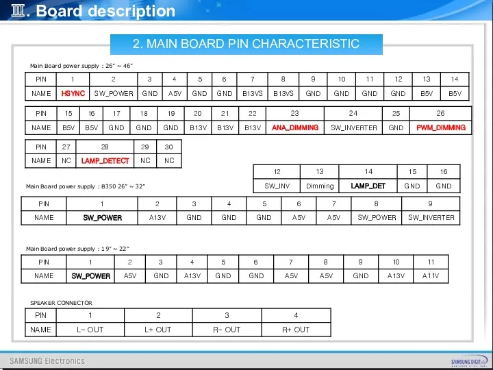
- 57. Ⅲ. Board description Main Board power supply : 26” ~ 46” SPEAKER CONNECTOR 2. MAIN BOARD
- 58. Analog Dimming ; Current Amplitude Control PWM Dimming 1. I-PWM ; DC(0~3.3V) signal 2. E-PWM ;
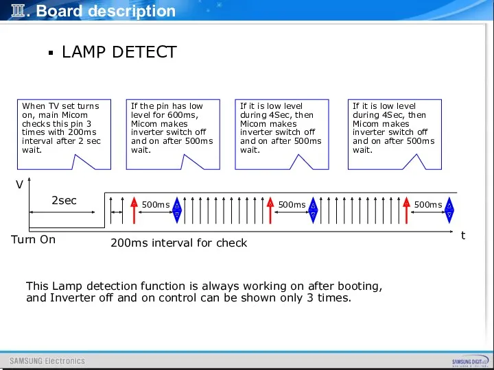
- 59. LAMP DETECT Ⅲ. Board description V t 2sec Turn On 200ms interval for check 500ms When
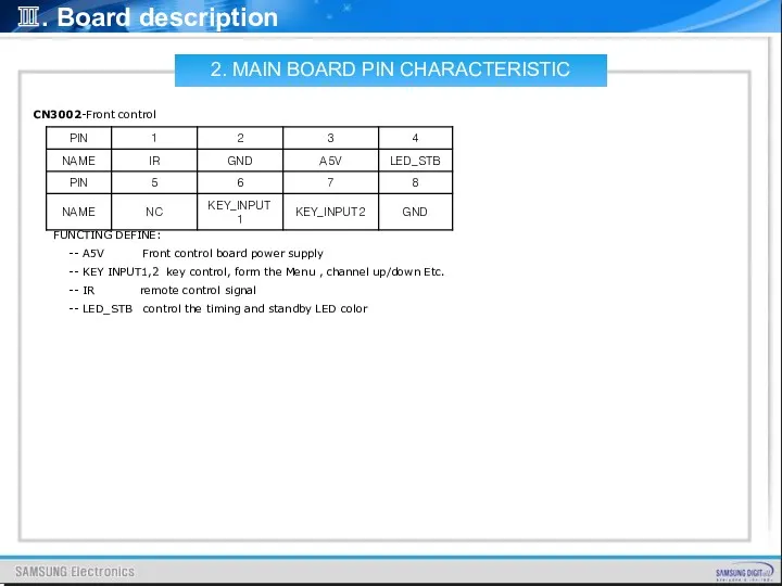
- 60. Ⅲ. Board description CN3002-Front control FUNCTING DEFINE: -- A5V Front control board power supply -- KEY
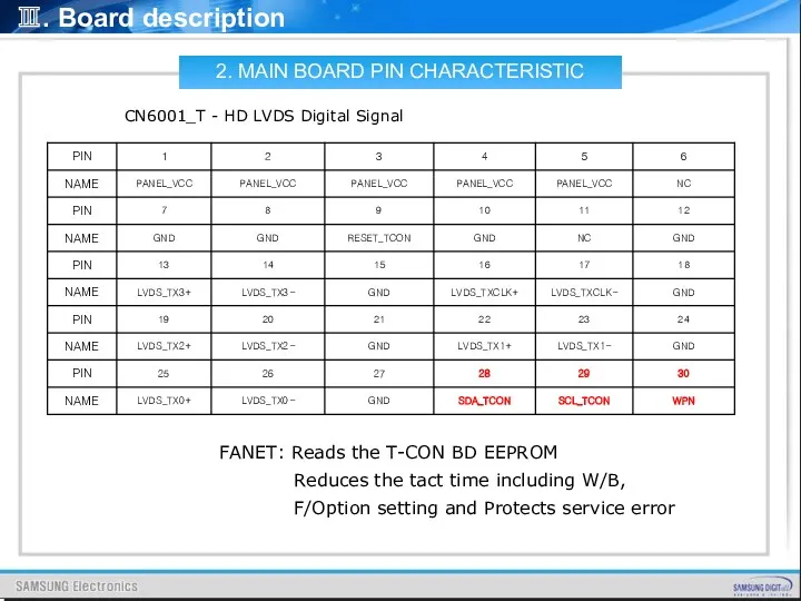
- 61. Ⅲ. Board description CN6001_T - HD LVDS Digital Signal 2. MAIN BOARD PIN CHARACTERISTIC FANET: Reads
- 62. 1.Sequence Spec_ Power AC 220V On (Phase :0도) Stand By +5V Power_ On +5V +13V Inverter_
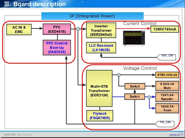
- 63. Ⅲ. Board description IP (Integrated Power) 1300V/140mA Inverter Transformer (EER2940x2) PFC (EED4018) LLC Resonant (LX1692B) PFC
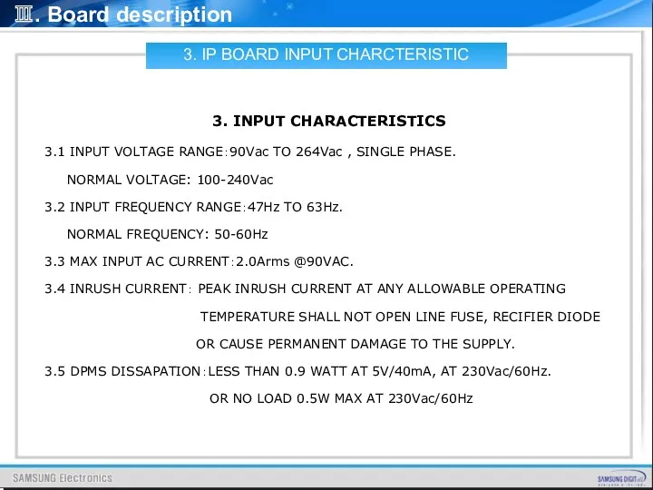
- 64. Ⅲ. Board description 3. IP BOARD INPUT CHARCTERISTIC 3. INPUT CHARACTERISTICS 3.1 INPUT VOLTAGE RANGE:90Vac TO
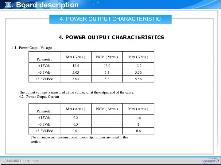
- 65. Ⅲ. Board description 4. POWER OUTPUT CHARACTERISTIC 4. POWER OUTPUT CHARACTERISTICS 4.1 . Power Output Voltage
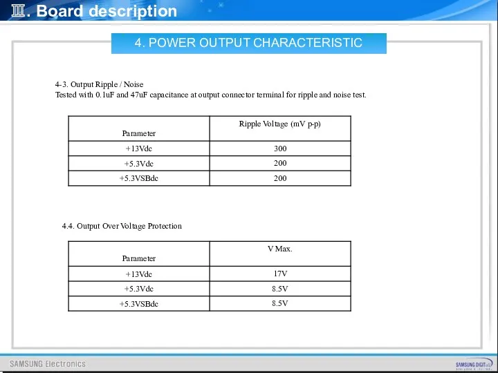
- 66. Ⅲ. Board description 4-3. Output Ripple / Noise Tested with 0.1uF and 47uF capacitance at output
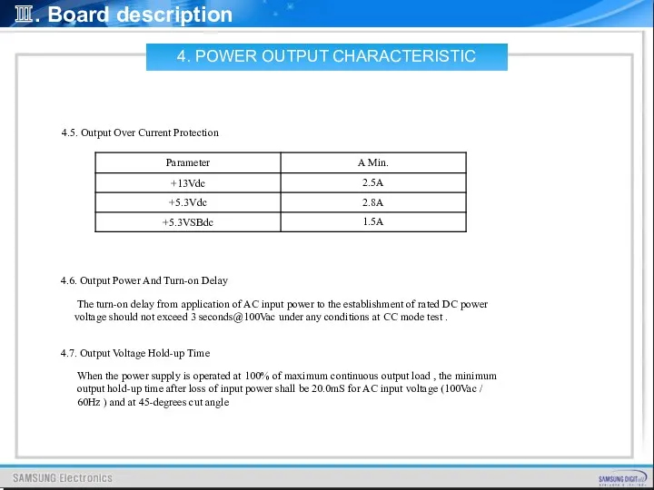
- 67. Ⅲ. Board description 4.5. Output Over Current Protection 4.6. Output Power And Turn-on Delay The turn-on
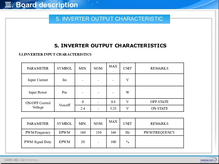
- 68. Ⅲ. Board description 5.1.INVERTER INPUT CHARACTERISTICS 5. INVERTER OUTPUT CHARACTERISTICS 5. INVERTER OUTPUT CHARACTERISTIC
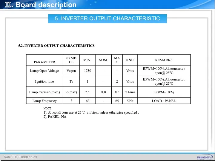
- 69. Ⅲ. Board description 5.2. INVERTER OUTPUT CHARACTERISTICS NOTE 1). All conditions are at 25℃ ambient unless
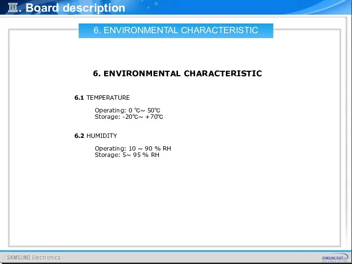
- 70. Ⅲ. Board description 6.1 TEMPERATURE Operating: 0 ℃~ 50℃ Storage: -20℃~ +70℃ 6.2 HUMIDITY Operating: 10
- 71. 7. Power BOARD LAYOUT 19” SMPS Board AC INPUT DC Regulation Inverter Transformer Ⅲ. Board description
- 72. 7. POWER BOARD LAYOUT 22” SMPS Board AC INPUT DC Regulation Inverter Transformer Ⅲ. Board description
- 73. 7. POWER BOARD LAYOUT 26” IP Board AC INPUT DC Regulation Inverter Supply Part PFC Coil
- 74. 7. POWER BOARD LAYOUT 32” IP Board AC INPUT DC Regulation Inverter Supply Part PFC Coil
- 75. 7. POWER BOARD LAYOUT 37” IP Board AC INPUT DC Regulation Inverter Supply Part PFC Coil
- 76. 7. POWER BOARD LAYOUT 40” IP Board AC INPUT DC Regulation Inverter Supply Part PFC Coil
- 77. 7. POWER BOARD LAYOUT 46” SMPS Board AC INPUT DC Regulation Inverter Supply Part PFC Coil
- 78. Ⅲ. Board description 8.1 AC INPUT CONNECTOR [PD801S] 8. IP BOARD PIN CHARACTERISTICS PD801S:DAC-11P (DONGIL) 8.
- 79. Ⅲ. Board description 8.2 POWER OUTPUT CONNECOTR PIN ASSIGNMENT[CNM801] CN802:SMW200-30C(YEONHO) 8. IP BOARD PIN CHARACTERISTIC
- 80. Ⅲ. Board description Test Condition of the circuit [Jig Test] 8. IP BOARD PIN CHARACTERISTIC
- 81. Ⅲ. Board description GENERAL REQUIREMENT OF WORLDWIDE STANDARD 1. MEET SAFETY REQUIRMENT. UL60065, CSA C22.2 NO.60065,
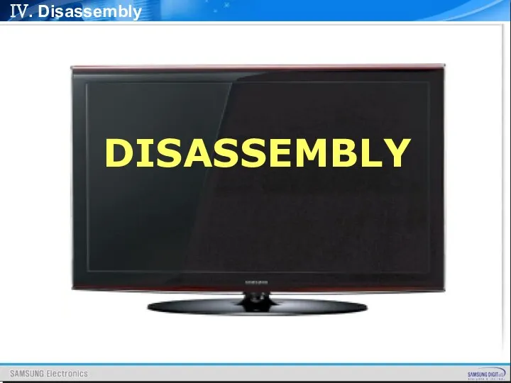
- 82. IV. Disassembly DISASSEMBLY
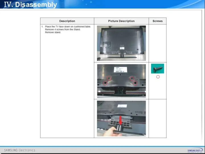
- 83. IV. Disassembly
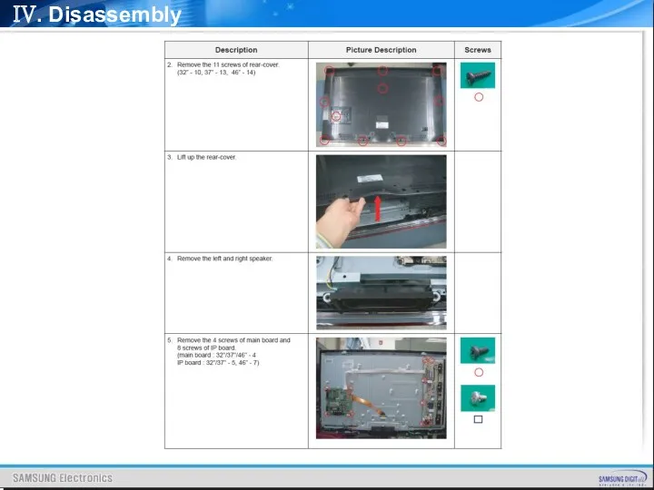
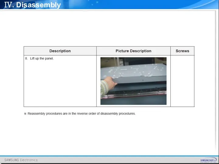
- 84. IV. Disassembly
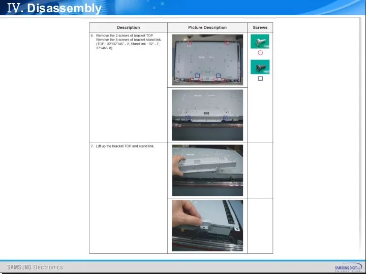
- 85. IV. Disassembly
- 86. IV. Disassembly
- 87. V. Trouble Shooting CONTENTS Power Trouble Shooting Analog Part Digital Part Sound Part Flow Chart &
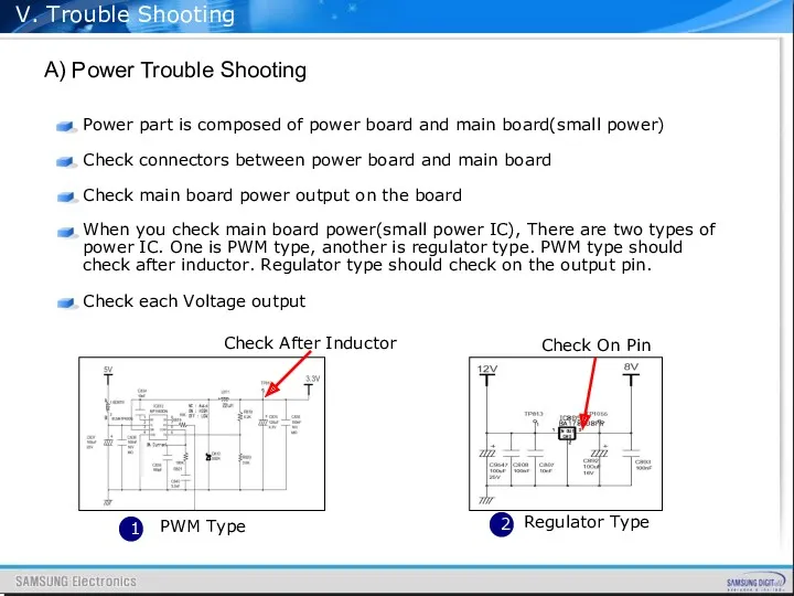
- 88. V. Trouble Shooting A) Power Trouble Shooting Power part is composed of power board and main
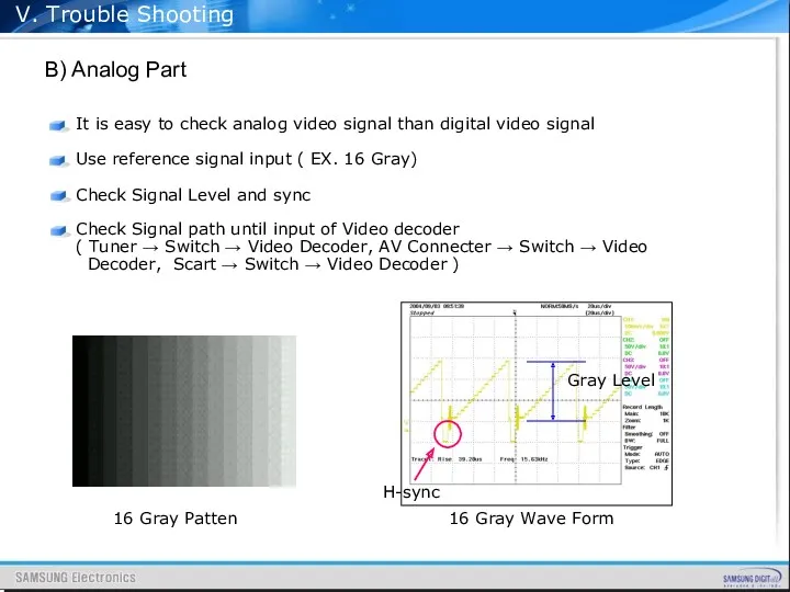
- 89. V. Trouble Shooting B) Analog Part It is easy to check analog video signal than digital
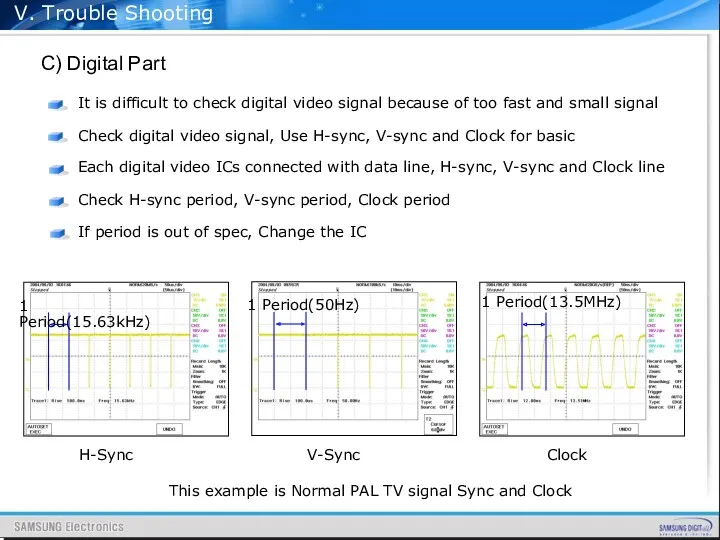
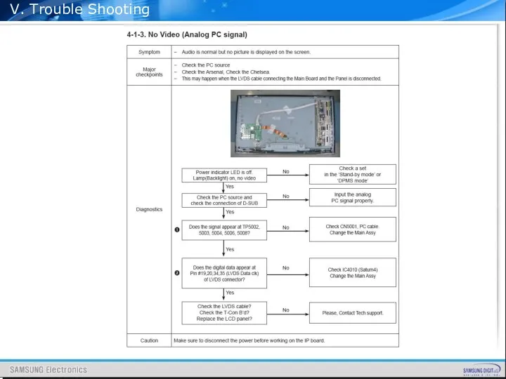
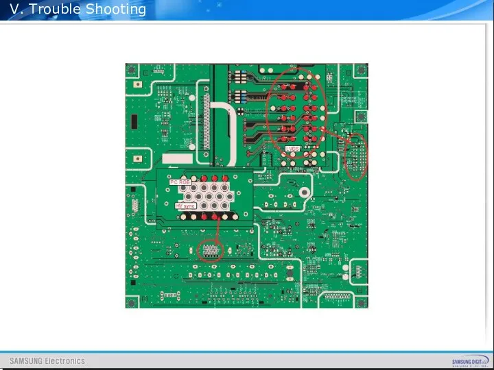
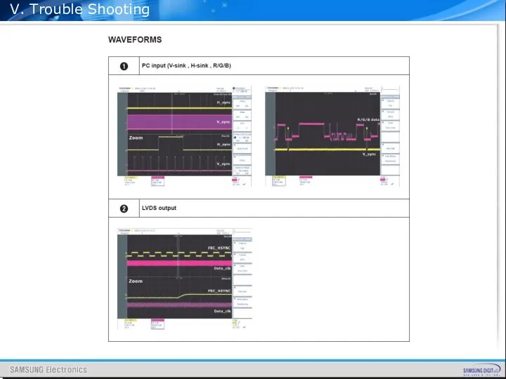
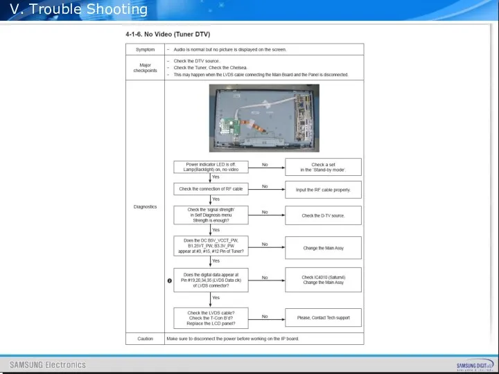
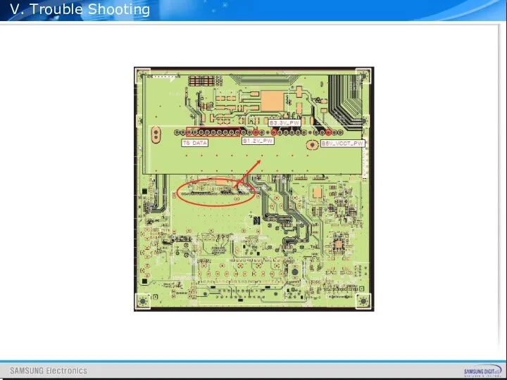
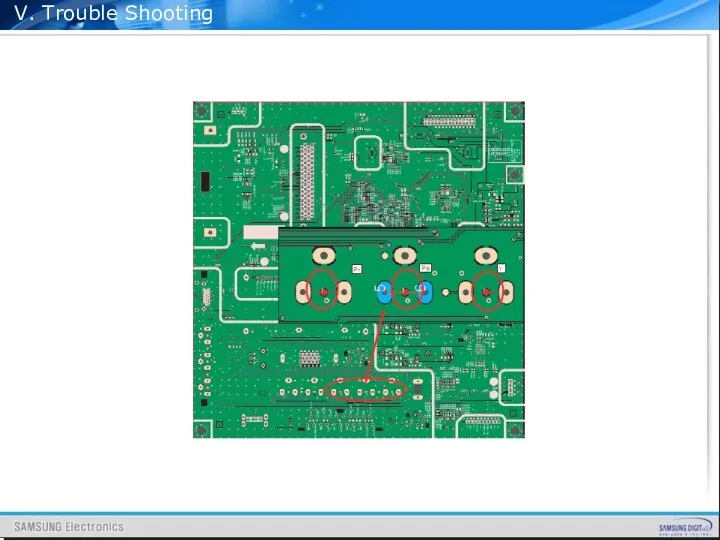
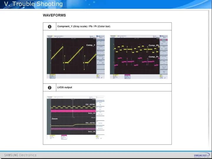
- 90. V. Trouble Shooting C) Digital Part It is difficult to check digital video signal because of
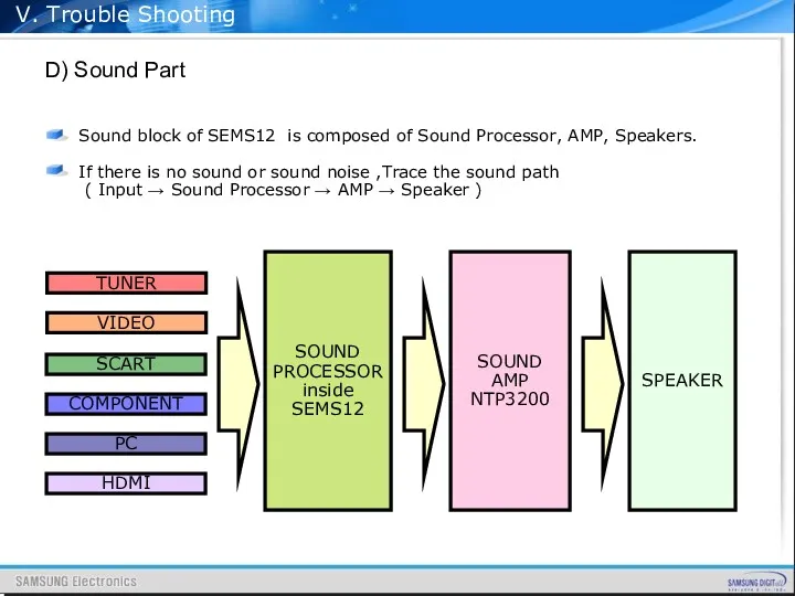
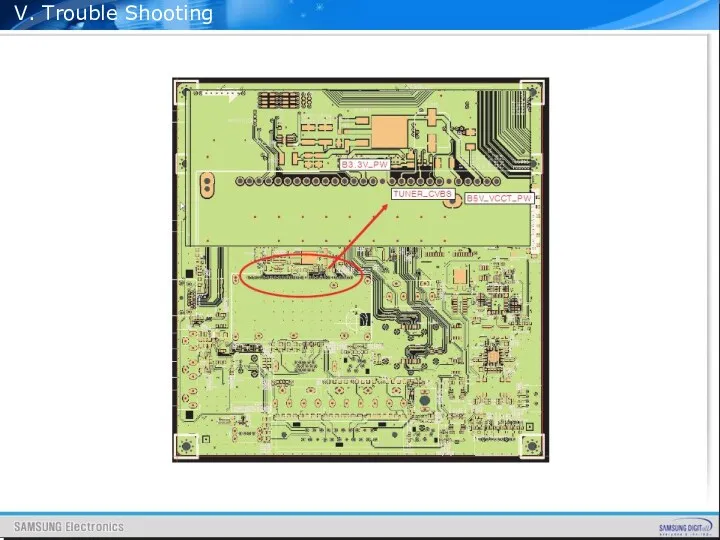
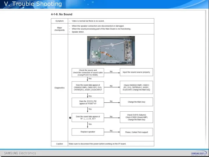
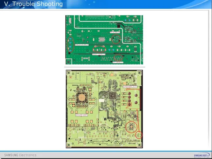
- 91. V. Trouble Shooting D) Sound Part Sound block of SEMS12 is composed of Sound Processor, AMP,
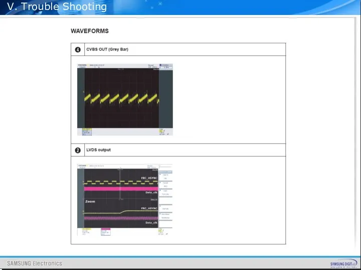
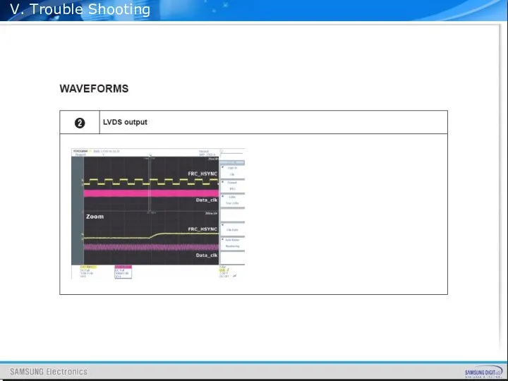
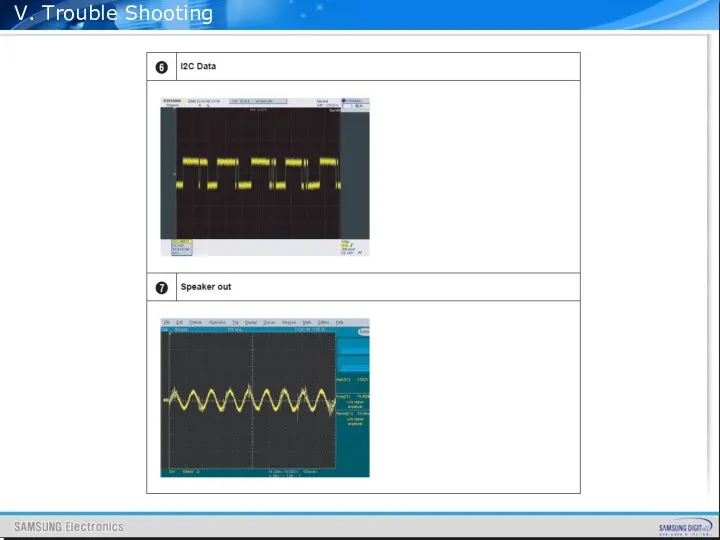
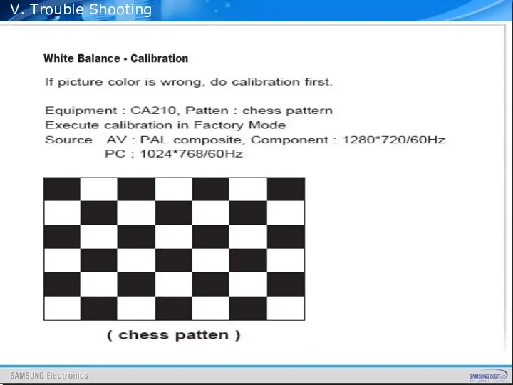
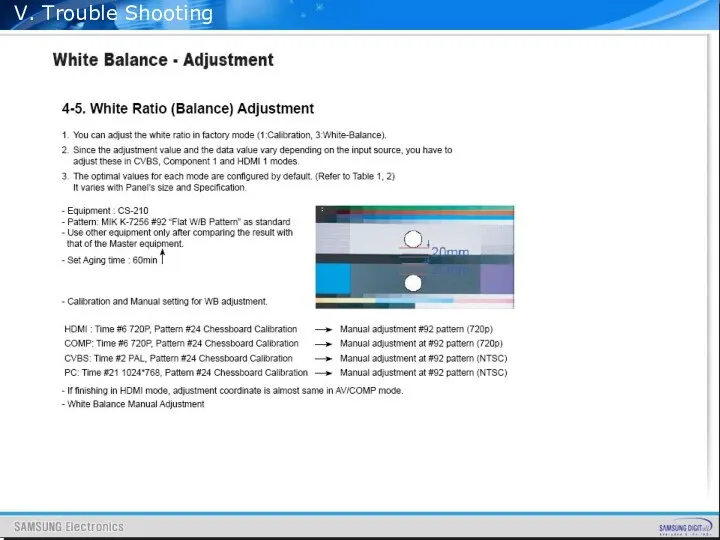
- 92. V. Trouble Shooting
- 93. V. Trouble Shooting
- 94. V. Trouble Shooting
- 95. V. Trouble Shooting
- 96. V. Trouble Shooting
- 97. V. Trouble Shooting
- 98. V. Trouble Shooting
- 99. V. Trouble Shooting
- 100. V. Trouble Shooting
- 101. V. Trouble Shooting
- 102. V. Trouble Shooting
- 103. V. Trouble Shooting
- 104. V. Trouble Shooting
- 105. V. Trouble Shooting
- 106. V. Trouble Shooting
- 107. V. Trouble Shooting
- 108. V. Trouble Shooting
- 109. V. Trouble Shooting
- 110. V. Trouble Shooting
- 111. V. Trouble Shooting
- 112. V. Trouble Shooting
- 113. V. Trouble Shooting
- 114. Saturn4 DVB (Code Release) -------------------------------------------------- Full HD B'd : T-CRLPEUFC-0152 Checksum : 0x3BDA) HD B'd :
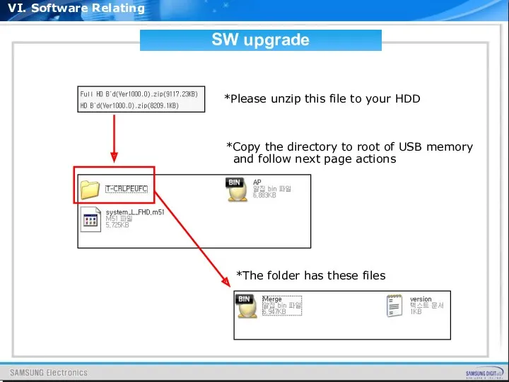
- 115. VI. Software Relating SW upgrade *Copy the directory to root of USB memory and follow next
- 116. VI. Software Relating SW upgrade
- 117. HOW TO UPGRADE with JIG VI. Software Relating TV Main S/W
- 118. HOW TO UPGRADE with JIG VI. Software Relating
- 119. HOW TO UPGRADE with JIG VI. Software Relating
- 120. Appendix Feature & Specification PC timing of FHD & HD Comparison of User key pad Signal
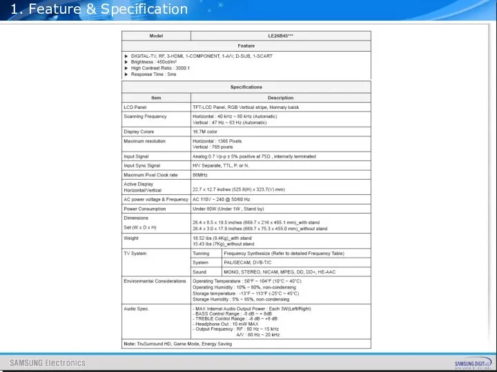
- 121. 1. Feature & Specification
- 122. 1. Feature & Specification
- 123. 1. Feature & Specification
- 124. 1. Feature & Specification
- 125. 1. Feature & Specification
- 126. 1. Feature & Specification
- 127. 1. Feature & Specification
- 128. 1. Feature & Specification
- 129. 2. PC Timing
- 130. 2. PC Timing
- 131. Touch Type [B350,B460,B650 models] Tact Switch Type [B450,B530 models] 3. Comparison of User key pad
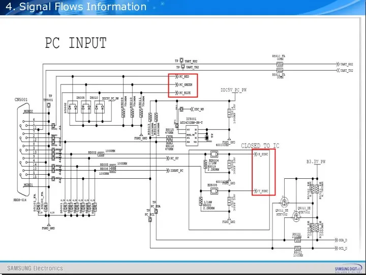
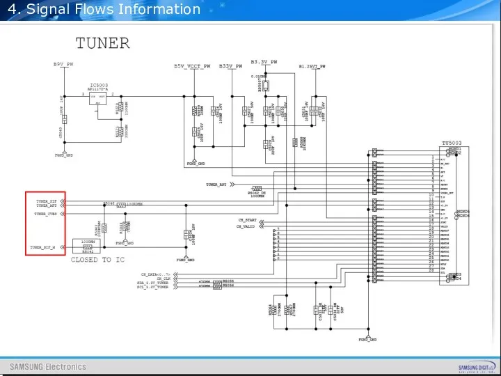
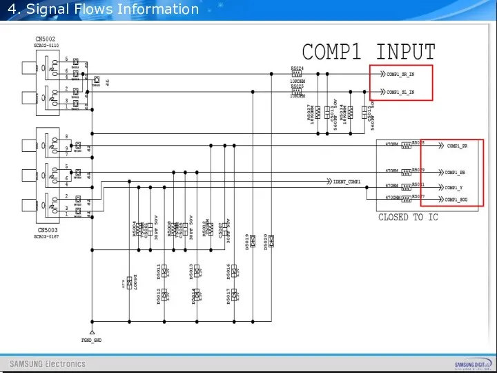
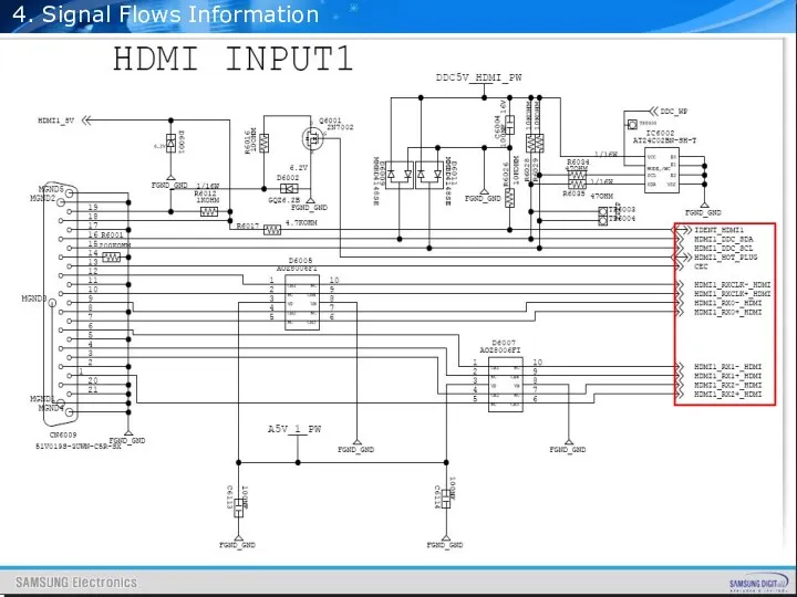
- 132. 4. Signal Flows Information Contents PC Input Tuner Input Component Input HDMI Input SCART Input AV
- 133. 4. Signal Flows Information
- 134. 4. Signal Flows Information
- 135. 4. Signal Flows Information
- 136. 4. Signal Flows Information
- 137. 4. Signal Flows Information
- 138. 4. Signal Flows Information
- 139. 4. Signal Flows Information Tuner, AV, SCART, COMPONENT ALL SOUND INPUT SIGNALS go into SEMS12 directly,
- 140. 4. Signal Flows Information Tuner, AV, SCART, COMPONENT ALL VIDEO INPUT SIGNALS go into SEMS12 directly,
- 141. 4. Signal Flows Information 3 HDMI VIDEO INPUT SIGNALS go into SEMS12 directly, there is no
- 142. 4. Signal Flows Information DDR SIGNALS go into SEMS12 directly
- 143. 4. Signal Flows Information CI SIGNALS go into SEMS12 directly
- 144. 4. Signal Flows Information LVDS SIGNALS go into TCON BD directly
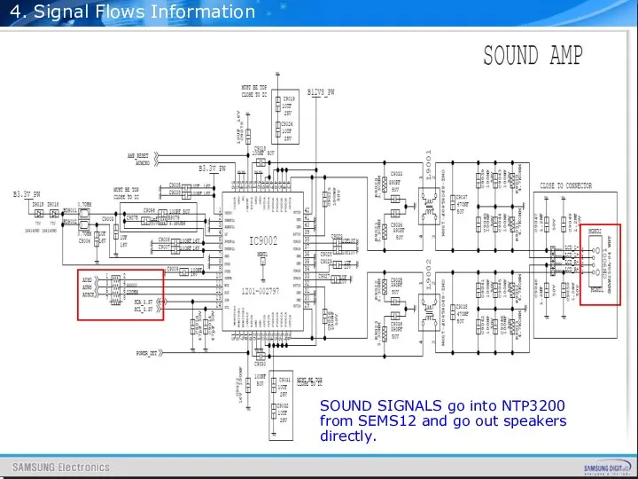
- 145. 4. Signal Flows Information SOUND SIGNALS go into NTP3200 from SEMS12 and go out speakers directly.
- 146. Contents 32” IP Schematic Diagram 37” IP Schematic Diagram 40” IP Schematic Diagram 46” IP Schematic
- 147. 5. IP Schematic Diagram : 32”
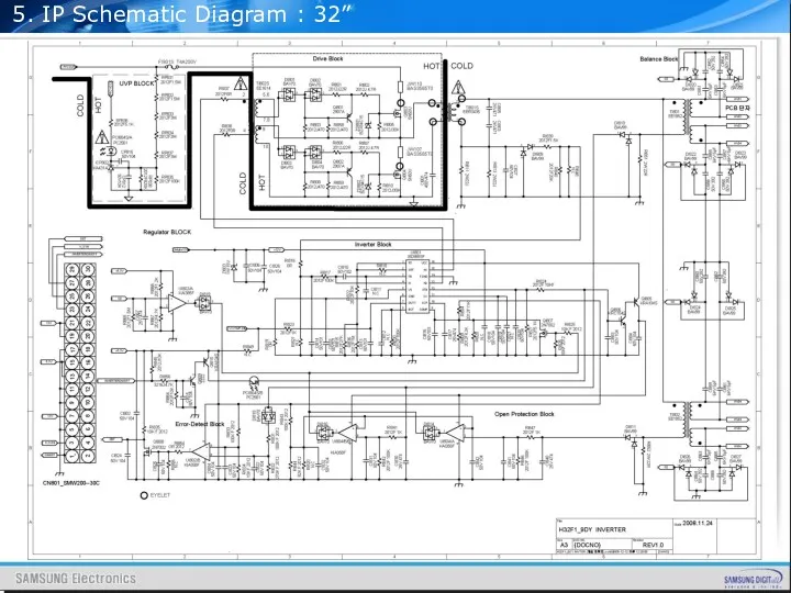
- 148. 5. IP Schematic Diagram : 32”
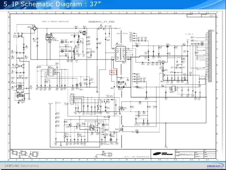
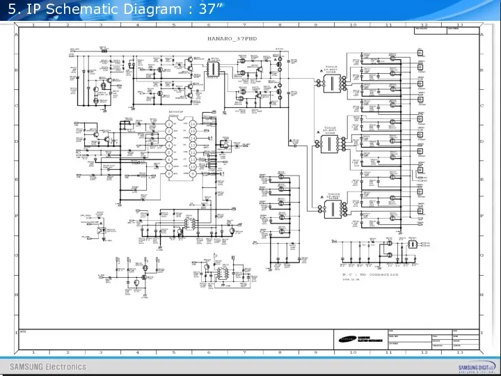
- 149. 5. IP Schematic Diagram : 37”
- 150. 5. IP Schematic Diagram : 37”
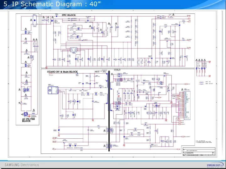
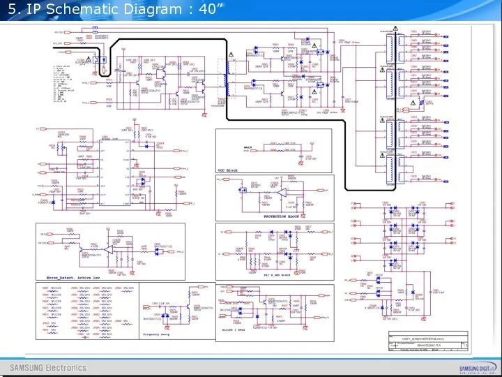
- 151. 5. IP Schematic Diagram : 40”
- 152. 5. IP Schematic Diagram : 40”
- 153. 5. IP Schematic Diagram : 46”
- 154. 5. IP Schematic Diagram : 46”
- 156. Скачать презентацию
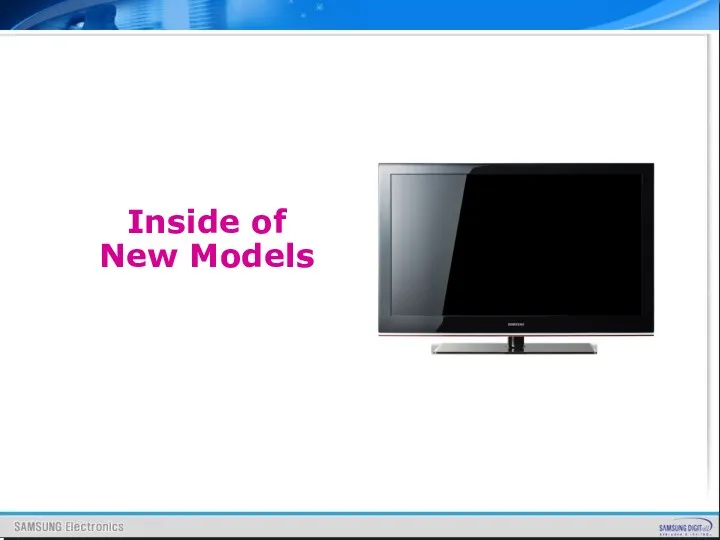
Inside of
New Models
Inside of
New Models
CONTENTS
Introduction
Inside of Models
Board description
Disassembly
Trouble Shooting
Software Relating
Appendix
CONTENTS
Introduction
Inside of Models
Board description
Disassembly
Trouble Shooting
Software Relating
Appendix
Introduction
Best Picture Quality
Simple Function, New Design
Acceptable Price
Support HDMI
New Functions
Introduction
Best Picture Quality
Simple Function, New Design
Acceptable Price
Support HDMI
New Functions
II. Inside of New Model
II. Inside of New Model
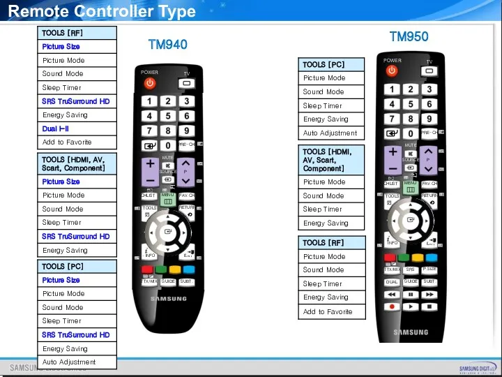
TM950
TM940
Remote Controller Type
TM950
TM940
Remote Controller Type
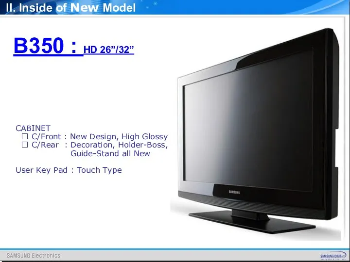
B350 : HD 26”/32”
CABINET
? C/Front : New Design, High
B350 : HD 26”/32”
CABINET
? C/Front : New Design, High
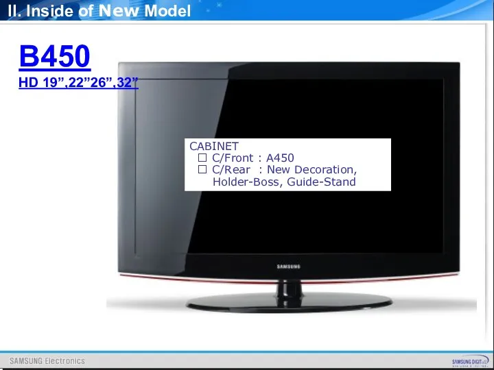
CABINET
? C/Front : A450
? C/Rear : New Decoration,
CABINET
? C/Front : A450
? C/Rear : New Decoration,
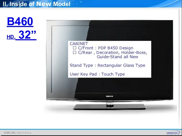
B460
HD, 32”
CABINET
? C/Front : PDP B450 Design
? C/Rear
B460
HD, 32”
CABINET
? C/Front : PDP B450 Design
? C/Rear
CABINET
? C/Front : A550 P3
? C/Rear, New Decoration,
CABINET
? C/Front : A550 P3
? C/Rear, New Decoration,
B650
HD: 19”/22”
CABINET
? C/Front : New, Toc
? C/Rear :
B650
HD: 19”/22”
CABINET
? C/Front : New, Toc
? C/Rear :
Control & Connection Panel
New Model
II. Inside of New Model
Control & Connection Panel
New Model
II. Inside of New Model
Last year Model
II. Inside of New Model
Last year Model
II. Inside of New Model
Control & Connection Panel
II. Inside of New Model
Control & Connection Panel
II. Inside of New Model
Control & Connection Panel
II. Inside of New Model
Control & Connection Panel
II. Inside of New Model
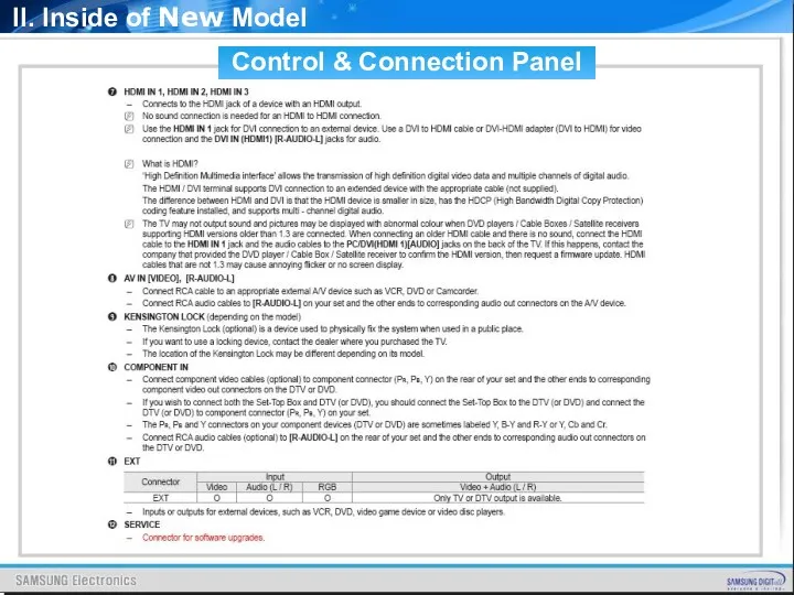
Control & Connection Panel
II. Inside of New Model
Control & Connection Panel
II. Inside of New Model
II. Inside of New Model
II. Inside of New Model
Audio AMP
NTP3200
ANT
Input Jack
MSTAR
Saturn4
(371-BGA)
Micom
3D Comb
Multi Decoder
(NTSC/PAL/SECAM
MPEG-2 AV/4/H.264)
De-interlacer
Scaler
LVDS Out
(10bit-dual)
Caption/TTX
10bit Process
Sound Process
USB 2.0
SXGA Output
HDMI
Audio AMP
NTP3200
ANT
Input Jack
MSTAR
Saturn4
(371-BGA)
Micom
3D Comb
Multi Decoder
(NTSC/PAL/SECAM
MPEG-2 AV/4/H.264)
De-interlacer
Scaler
LVDS Out
(10bit-dual)
Caption/TTX
10bit Process
Sound Process
USB 2.0
SXGA Output
HDMI
Audio AMP
NTP3200
ANT
Input Jack
MSTAR
Saturn4
(371-BGA)
Micom
3D Comb
Multi Decoder
(NTSC/PAL/SECAM
MPEG-2 AV/4/H.264)
De-interlacer
Scaler
LVDS Out
(10bit-dual)
Caption/TTX
10bit Process
Sound Process
USB 2.0
SXGA Output
HDMI
Audio AMP
NTP3200
ANT
Input Jack
MSTAR
Saturn4
(371-BGA)
Micom
3D Comb
Multi Decoder
(NTSC/PAL/SECAM
MPEG-2 AV/4/H.264)
De-interlacer
Scaler
LVDS Out
(10bit-dual)
Caption/TTX
10bit Process
Sound Process
USB 2.0
SXGA Output
HDMI
Audio AMP
NTP3200
ANT
Input Jack
MSTAR
Saturn4
(371-BGA)
Micom
3D Comb
Multi Decoder
(NTSC/PAL/SECAM
MPEG-2 AV/4/H.264)
De-interlacer
Scaler
LVDS Out
(10bit-dual)
Caption/TTX
10bit Process
Sound Process
USB 2.0
SXGA Output
HDMI
Audio AMP
NTP3200
ANT
Input Jack
MSTAR
Saturn4
(371-BGA)
Micom
3D Comb
Multi Decoder
(NTSC/PAL/SECAM
MPEG-2 AV/4/H.264)
De-interlacer
Scaler
LVDS Out
(10bit-dual)
Caption/TTX
10bit Process
Sound Process
USB 2.0
SXGA Output
HDMI
Audio AMP
NTP3200
ANT
Input Jack
MSTAR
Saturn4
(371-BGA)
Micom
3D Comb
Multi Decoder
(NTSC/PAL/SECAM
MPEG-2 AV/4/H.264)
De-interlacer
Scaler
LVDS Out
(10bit-dual)
Caption/TTX
10bit Process
Sound Process
USB 2.0
SXGA Output
HDMI
Audio AMP
NTP3200
ANT
Input Jack
MSTAR
Saturn4
(371-BGA)
Micom
3D Comb
Multi Decoder
(NTSC/PAL/SECAM
MPEG-2 AV/4/H.264)
De-interlacer
Scaler
LVDS Out
(10bit-dual)
Caption/TTX
10bit Process
Sound Process
USB 2.0
SXGA Output
HDMI
Audio AMP
NTP3200
ANT
Input Jack
MSTAR
Saturn4
(371-BGA)
Micom
3D Comb
Multi Decoder
(NTSC/PAL/SECAM
MPEG-2 AV/4/H.264)
De-interlacer
Scaler
LVDS Out
(10bit-dual)
Caption/TTX
10bit Process
Sound Process
USB 2.0
SXGA Output
HDMI
Audio AMP
NTP3200
ANT
Input Jack
MSTAR
Saturn4
(371-BGA)
Micom
3D Comb
Multi Decoder
(NTSC/PAL/SECAM
MPEG-2 AV/4/H.264)
De-interlacer
Scaler
LVDS Out
(10bit-dual)
Caption/TTX
10bit Process
Sound Process
USB 2.0
SXGA Output
HDMI
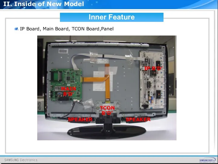
IP Board, Main Board, TCON Board,Panel
Inner Feature
IP B’D’
MAIN B’D’
SPEAKER
SPEAKER
TCON
IP Board, Main Board, TCON Board,Panel
Inner Feature
IP B’D’
MAIN B’D’
SPEAKER
SPEAKER
TCON
![Audio description [From Wikipedia, the free encyclopedia] Audio description refers](/_ipx/f_webp&q_80&fit_contain&s_1440x1080/imagesDir/jpg/201012/slide-23.jpg)
Audio description [From Wikipedia, the free encyclopedia]
Audio description refers to an
Audio description [From Wikipedia, the free encyclopedia]
Audio description refers to an
New Function : Audio Description
New Function : Audio Description
New Function : Dolby Digital Plus
Audio encoding/compression
Dolby Digital (also known as
New Function : Dolby Digital Plus
Audio encoding/compression
Dolby Digital (also known as
New Function : SRS TruSurround HD
Dialog Clarity. Audio creators today have
New Function : SRS TruSurround HD
Dialog Clarity. Audio creators today have
New Function : SRS TruSurround HD
Improved Bass. We know small speakers
New Function : SRS TruSurround HD
Improved Bass. We know small speakers
New Function : Self Diagnosis
1. Picture Test
Color Bar Test Pattern
2.
New Function : Self Diagnosis
1. Picture Test
Color Bar Test Pattern
2.
New Function : Self Diagnosis
New Function : Self Diagnosis
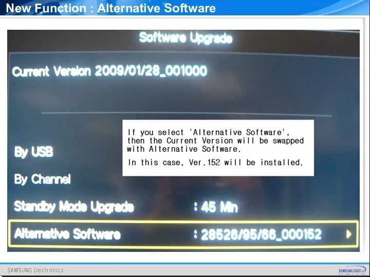
New Function : Alternative Software
New Function : Alternative Software
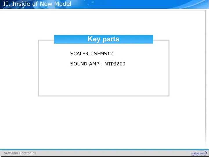
Key parts
SCALER : SEMS12
SOUND AMP : NTP3200
II. Inside of New Model
Key parts
SCALER : SEMS12
SOUND AMP : NTP3200
II. Inside of New Model
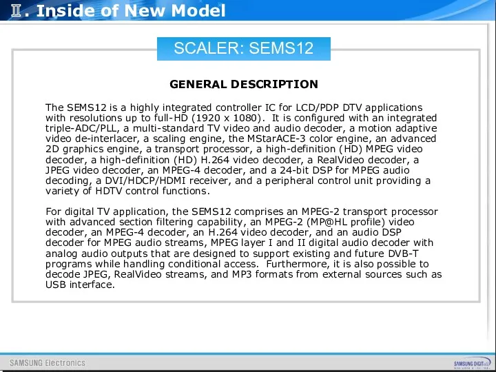
SCALER: SEMS12
GENERAL DESCRIPTION
The SEMS12 is a highly integrated controller IC for
SCALER: SEMS12
GENERAL DESCRIPTION
The SEMS12 is a highly integrated controller IC for
SCALER: SEMS12
FEATURES
☞ Transport Stream De-multiplexer
Two external TS inputs and one
SCALER: SEMS12
FEATURES
☞ Transport Stream De-multiplexer
Two external TS inputs and one
SCALER: SEMS12
☞ MPEG-4 Video Decoder
ISO/IEC 14496-2 MPEG-4 ASP video decoding
Supports
SCALER: SEMS12
☞ MPEG-4 Video Decoder
ISO/IEC 14496-2 MPEG-4 ASP video decoding
Supports
SCALER: SEMS12
☞ NTSC/PAL/SECAM Video Decoder
Supports NTSC-M, NTSC-J, NTSC-4.43, PAL (B,D,G,H,M,N,I,Nc),
SCALER: SEMS12
☞ NTSC/PAL/SECAM Video Decoder
Supports NTSC-M, NTSC-J, NTSC-4.43, PAL (B,D,G,H,M,N,I,Nc),
SCALER: SEMS12
☞ Multi-Standard TV Sound Processor
Supports BTSC/A2/EIA-J demodulation in NTSC
SCALER: SEMS12
☞ Multi-Standard TV Sound Processor
Supports BTSC/A2/EIA-J demodulation in NTSC
SCALER: SEMS12
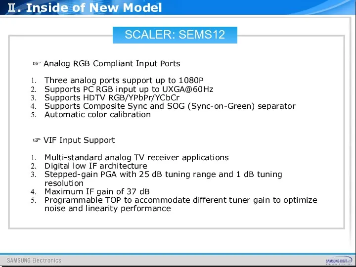
☞ Analog RGB Compliant Input Ports
Three analog ports support
SCALER: SEMS12
☞ Analog RGB Compliant Input Ports
Three analog ports support
SCALER: SEMS12
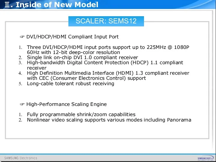
☞ DVI/HDCP/HDMI Compliant Input Port
Three DVI/HDCP/HDMI input ports support
SCALER: SEMS12
☞ DVI/HDCP/HDMI Compliant Input Port
Three DVI/HDCP/HDMI input ports support
SCALER: SEMS12
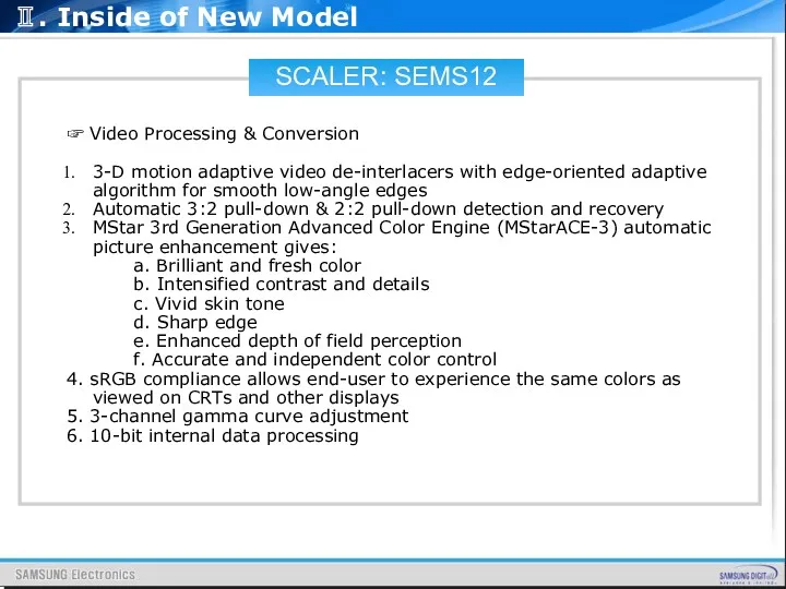
☞ Video Processing & Conversion
3-D motion adaptive video de-interlacers
SCALER: SEMS12
☞ Video Processing & Conversion
3-D motion adaptive video de-interlacers
SCALER: SEMS12
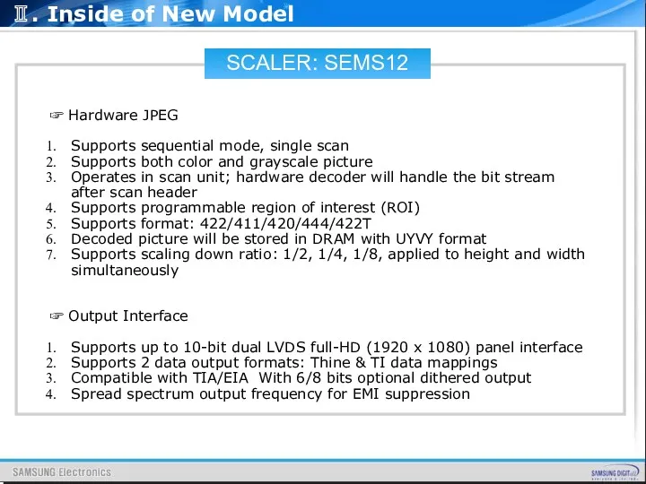
☞ Hardware JPEG
Supports sequential mode, single scan
Supports both
SCALER: SEMS12
☞ Hardware JPEG
Supports sequential mode, single scan
Supports both
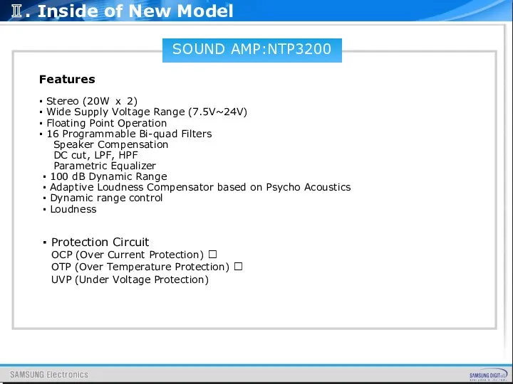
SOUND AMP:NTP3200
Features
▪ Stereo (20W ⅹ 2)
▪ Wide Supply Voltage Range (7.5V~24V)
▪
SOUND AMP:NTP3200
Features
▪ Stereo (20W ⅹ 2)
▪ Wide Supply Voltage Range (7.5V~24V)
▪
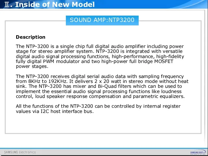
SOUND AMP:NTP3200
Description
The NTP-3200 is a single chip full digital audio amplifier
SOUND AMP:NTP3200
Description
The NTP-3200 is a single chip full digital audio amplifier
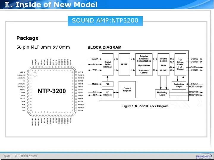
SOUND AMP:NTP3200
Package
56 pin MLF 8mm by 8mm
Ⅱ. Inside of New Model
SOUND AMP:NTP3200
Package
56 pin MLF 8mm by 8mm
Ⅱ. Inside of New Model
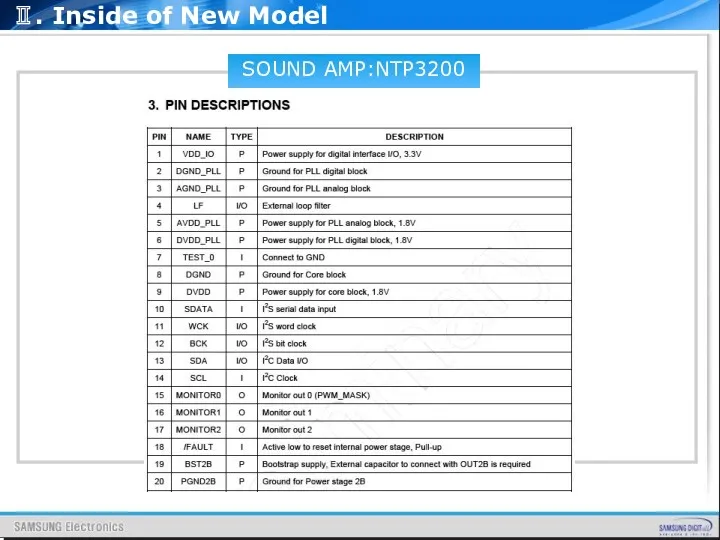
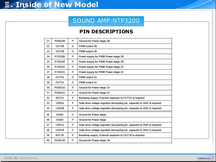
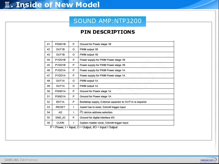
SOUND AMP:NTP3200
PIN DESCRIPTIONS
Ⅱ. Inside of New Model
SOUND AMP:NTP3200
PIN DESCRIPTIONS
Ⅱ. Inside of New Model
SOUND AMP:NTP3200
PIN DESCRIPTIONS
Ⅱ. Inside of New Model
SOUND AMP:NTP3200
PIN DESCRIPTIONS
Ⅱ. Inside of New Model
SOUND AMP:NTP3200
PIN DESCRIPTIONS
Ⅱ. Inside of New Model
SOUND AMP:NTP3200
PIN DESCRIPTIONS
Ⅱ. Inside of New Model
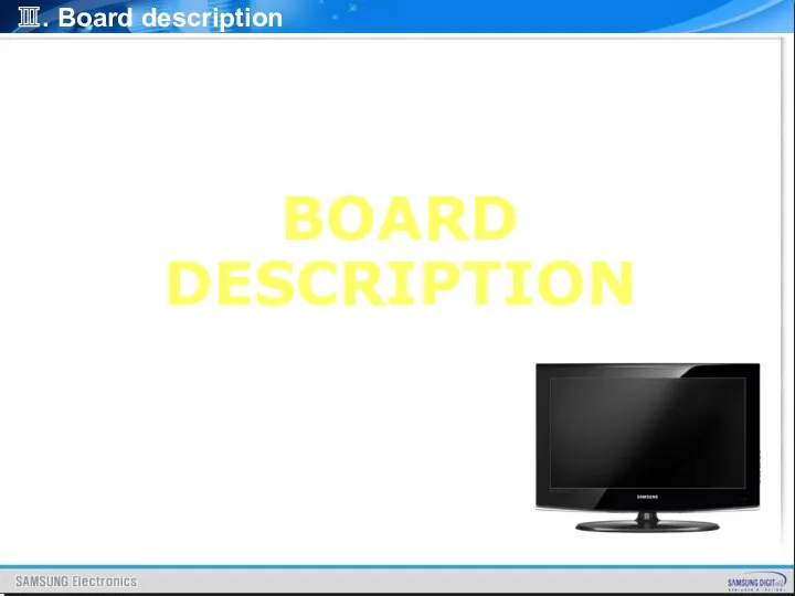
BOARD
DESCRIPTION
Ⅲ. Board description
BOARD
DESCRIPTION
Ⅲ. Board description
MAIN BOARD LAYOUT
MAIN BOARD PIN CHARACTERISTIC
IP BOARD INPUT CHARACTERISTIC
POWER OUTPUT CHARACTERISTIC
INVERTER
MAIN BOARD LAYOUT
MAIN BOARD PIN CHARACTERISTIC
IP BOARD INPUT CHARACTERISTIC
POWER OUTPUT CHARACTERISTIC
INVERTER
1. MAIN BOARD LAYOUT
FHD 32”/37”/40”/46” MAIN BOARD
192*195
Ⅲ. Board description
1. MAIN BOARD LAYOUT
FHD 32”/37”/40”/46” MAIN BOARD
192*195
Ⅲ. Board description
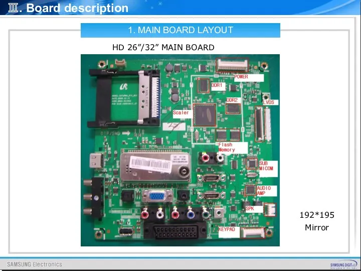
1. MAIN BOARD LAYOUT
HD 26”/32” MAIN BOARD
192*195
Mirror
Ⅲ. Board description
1. MAIN BOARD LAYOUT
HD 26”/32” MAIN BOARD
192*195
Mirror
Ⅲ. Board description
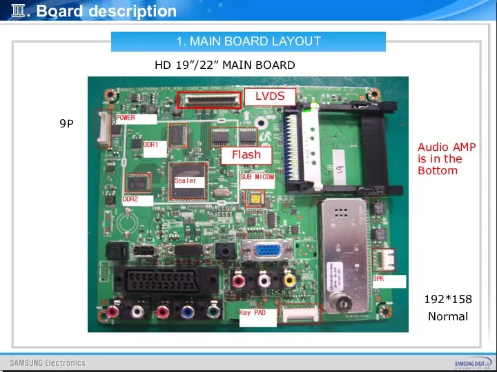
1. MAIN BOARD LAYOUT
HD 19”/22” MAIN BOARD
192*158
Normal
9P
Ⅲ. Board description
Audio AMP is
1. MAIN BOARD LAYOUT
HD 19”/22” MAIN BOARD
192*158
Normal
9P
Ⅲ. Board description
Audio AMP is
1. MAIN BOARD LAYOUT
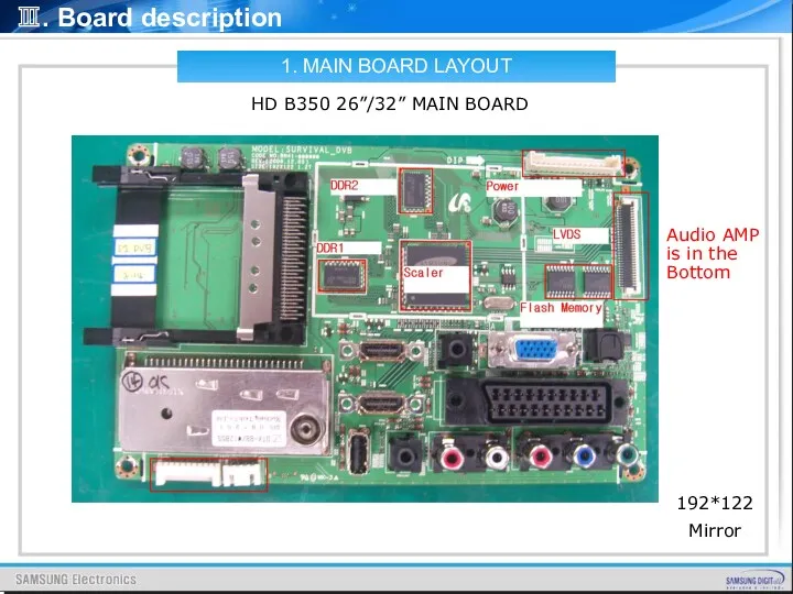
HD B350 26”/32” MAIN BOARD
192*122
Mirror
Ⅲ. Board description
Audio AMP
1. MAIN BOARD LAYOUT
HD B350 26”/32” MAIN BOARD
192*122
Mirror
Ⅲ. Board description
Audio AMP
1. MAIN BOARD LAYOUT
FHD 32”~46” ASIA DTV MAIN BOARD
Difference is only
1. MAIN BOARD LAYOUT
FHD 32”~46” ASIA DTV MAIN BOARD
Difference is only
1. MAIN BOARD LAYOUT
HD 19”~22” ASIA DTV MAIN BOARD
Difference is only
1. MAIN BOARD LAYOUT
HD 19”~22” ASIA DTV MAIN BOARD
Difference is only
Ⅲ. Board description
Main Board power supply : 26” ~ 46”
SPEAKER CONNECTOR
2.
Ⅲ. Board description
Main Board power supply : 26” ~ 46”
SPEAKER CONNECTOR
2.
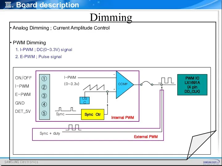
Analog Dimming ; Current Amplitude Control
PWM Dimming
1. I-PWM
Analog Dimming ; Current Amplitude Control
PWM Dimming
1. I-PWM
LAMP DETECT
Ⅲ. Board description
V
t
2sec
Turn On
200ms interval for check
500ms
When TV set turns
LAMP DETECT
Ⅲ. Board description
V
t
2sec
Turn On
200ms interval for check
500ms
When TV set turns
Ⅲ. Board description
CN3002-Front control
FUNCTING DEFINE:
-- A5V Front control board
Ⅲ. Board description
CN3002-Front control
FUNCTING DEFINE:
-- A5V Front control board
Ⅲ. Board description
CN6001_T - HD LVDS Digital Signal
2. MAIN BOARD
Ⅲ. Board description
CN6001_T - HD LVDS Digital Signal
2. MAIN BOARD
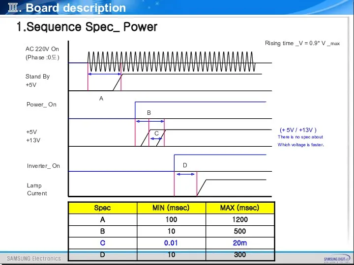
1.Sequence Spec_ Power
AC 220V On
(Phase :0도)
Stand By
+5V
Power_ On
+5V
+13V
Inverter_
1.Sequence Spec_ Power
AC 220V On
(Phase :0도)
Stand By
+5V
Power_ On
+5V
+13V
Inverter_
Ⅲ. Board description
IP (Integrated Power)
1300V/140mA
Inverter
Transformer
(EER2940x2)
PFC
(EED4018)
LLC Resonant
(LX1692B)
PFC Control
Boot-Up
(FAN7530)
13V/2.7A
T-con
STB5.3V/0.2A
Multi+STB
Transformer
(EER3124)
5.3V/3.1A
Main
13V/1.2A
Speaker
Flyback
(FSQ0765R)
Switch
AC IN & EMC
Switch
Current Control
Voltage
Ⅲ. Board description
3. IP BOARD INPUT CHARCTERISTIC
3. INPUT CHARACTERISTICS
3.1 INPUT VOLTAGE
Ⅲ. Board description
3. IP BOARD INPUT CHARCTERISTIC
3. INPUT CHARACTERISTICS
3.1 INPUT VOLTAGE
Ⅲ. Board description
4. POWER OUTPUT CHARACTERISTIC
4. POWER OUTPUT CHARACTERISTICS
4.1 . Power
Ⅲ. Board description
4. POWER OUTPUT CHARACTERISTIC
4. POWER OUTPUT CHARACTERISTICS
4.1 . Power
Ⅲ. Board description
4-3. Output Ripple / Noise
Tested with 0.1uF and 47uF
Ⅲ. Board description
4-3. Output Ripple / Noise
Tested with 0.1uF and 47uF
Ⅲ. Board description
4.5. Output Over Current Protection
4.6. Output Power And Turn-on
Ⅲ. Board description
4.5. Output Over Current Protection
4.6. Output Power And Turn-on
Ⅲ. Board description
5.1.INVERTER INPUT CHARACTERISTICS
5. INVERTER OUTPUT CHARACTERISTICS
5. INVERTER OUTPUT CHARACTERISTIC
Ⅲ. Board description
5.1.INVERTER INPUT CHARACTERISTICS
5. INVERTER OUTPUT CHARACTERISTICS
5. INVERTER OUTPUT CHARACTERISTIC
Ⅲ. Board description
5.2. INVERTER OUTPUT CHARACTERISTICS
NOTE
1). All conditions are at 25℃
Ⅲ. Board description
5.2. INVERTER OUTPUT CHARACTERISTICS
NOTE
1). All conditions are at 25℃
Ⅲ. Board description
6.1 TEMPERATURE
Operating: 0 ℃~ 50℃
Storage: -20℃~
Ⅲ. Board description
6.1 TEMPERATURE
Operating: 0 ℃~ 50℃
Storage: -20℃~
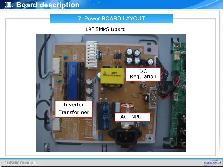
7. Power BOARD LAYOUT
19” SMPS Board
AC INPUT
DC Regulation
Inverter
Transformer
Ⅲ. Board description
7. Power BOARD LAYOUT
19” SMPS Board
AC INPUT
DC Regulation
Inverter
Transformer
Ⅲ. Board description
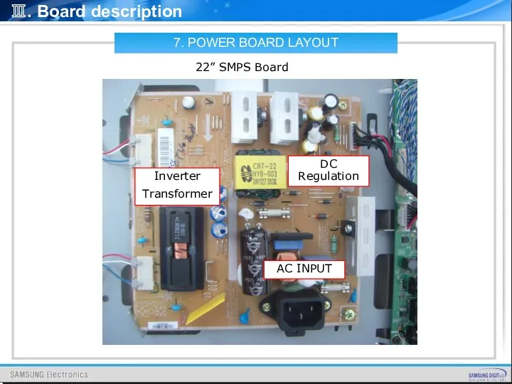
7. POWER BOARD LAYOUT
22” SMPS Board
AC INPUT
DC Regulation
Inverter
Transformer
Ⅲ. Board description
7. POWER BOARD LAYOUT
22” SMPS Board
AC INPUT
DC Regulation
Inverter
Transformer
Ⅲ. Board description
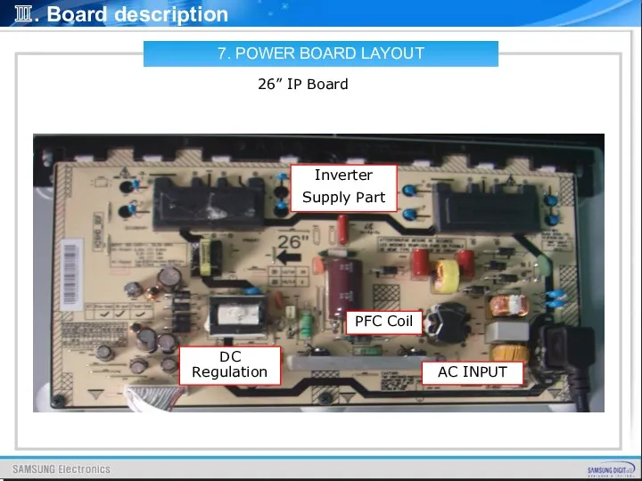
7. POWER BOARD LAYOUT
26” IP Board
AC INPUT
DC Regulation
Inverter
Supply Part
PFC Coil
Ⅲ. Board
7. POWER BOARD LAYOUT
26” IP Board
AC INPUT
DC Regulation
Inverter
Supply Part
PFC Coil
Ⅲ. Board
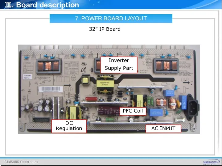
7. POWER BOARD LAYOUT
32” IP Board
AC INPUT
DC Regulation
Inverter
Supply Part
PFC Coil
Ⅲ. Board
7. POWER BOARD LAYOUT
32” IP Board
AC INPUT
DC Regulation
Inverter
Supply Part
PFC Coil
Ⅲ. Board
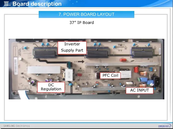
7. POWER BOARD LAYOUT
37” IP Board
AC INPUT
DC Regulation
Inverter
Supply Part
PFC Coil
Ⅲ. Board
7. POWER BOARD LAYOUT
37” IP Board
AC INPUT
DC Regulation
Inverter
Supply Part
PFC Coil
Ⅲ. Board
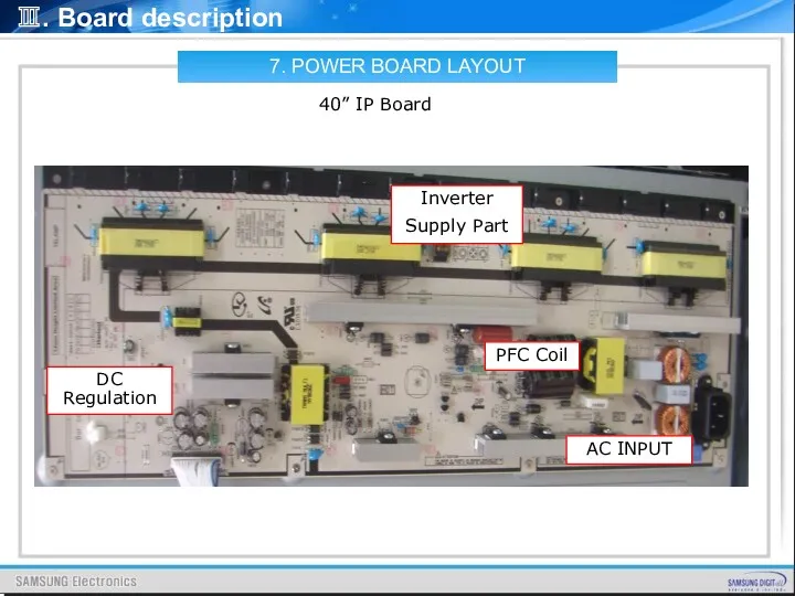
7. POWER BOARD LAYOUT
40” IP Board
AC INPUT
DC Regulation
Inverter
Supply Part
PFC Coil
Ⅲ. Board
7. POWER BOARD LAYOUT
40” IP Board
AC INPUT
DC Regulation
Inverter
Supply Part
PFC Coil
Ⅲ. Board
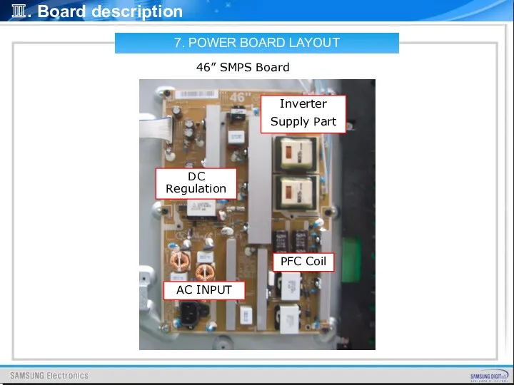
7. POWER BOARD LAYOUT
46” SMPS Board
AC INPUT
DC Regulation
Inverter
Supply Part
PFC Coil
Ⅲ. Board
7. POWER BOARD LAYOUT
46” SMPS Board
AC INPUT
DC Regulation
Inverter
Supply Part
PFC Coil
Ⅲ. Board
![Ⅲ. Board description 8.1 AC INPUT CONNECTOR [PD801S] 8. IP](/_ipx/f_webp&q_80&fit_contain&s_1440x1080/imagesDir/jpg/201012/slide-77.jpg)
Ⅲ. Board description
8.1 AC INPUT CONNECTOR [PD801S]
8. IP BOARD PIN CHARACTERISTICS
PD801S:DAC-11P
Ⅲ. Board description
8.1 AC INPUT CONNECTOR [PD801S]
8. IP BOARD PIN CHARACTERISTICS
PD801S:DAC-11P
![Ⅲ. Board description 8.2 POWER OUTPUT CONNECOTR PIN ASSIGNMENT[CNM801] CN802:SMW200-30C(YEONHO) 8. IP BOARD PIN CHARACTERISTIC](/_ipx/f_webp&q_80&fit_contain&s_1440x1080/imagesDir/jpg/201012/slide-78.jpg)
Ⅲ. Board description
8.2 POWER OUTPUT CONNECOTR PIN ASSIGNMENT[CNM801]
CN802:SMW200-30C(YEONHO)
8. IP BOARD
Ⅲ. Board description
8.2 POWER OUTPUT CONNECOTR PIN ASSIGNMENT[CNM801]
CN802:SMW200-30C(YEONHO)
8. IP BOARD
![Ⅲ. Board description Test Condition of the circuit [Jig Test] 8. IP BOARD PIN CHARACTERISTIC](/_ipx/f_webp&q_80&fit_contain&s_1440x1080/imagesDir/jpg/201012/slide-79.jpg)
Ⅲ. Board description
Test Condition of the circuit [Jig Test]
8. IP BOARD
Ⅲ. Board description
Test Condition of the circuit [Jig Test]
8. IP BOARD
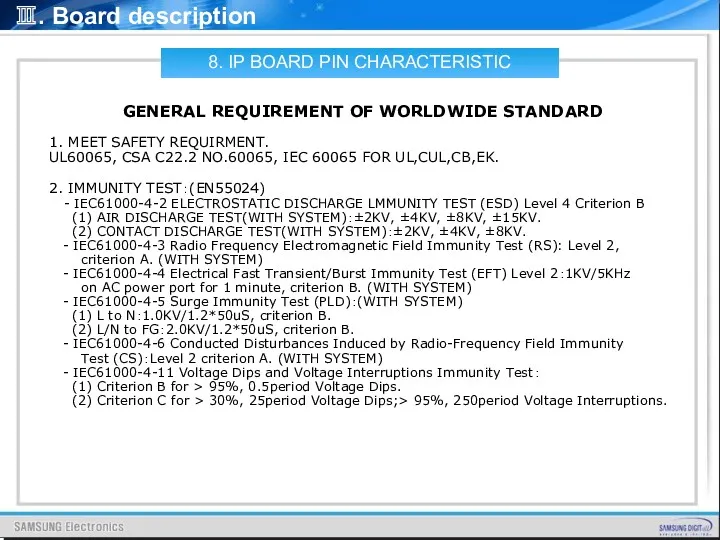
Ⅲ. Board description
GENERAL REQUIREMENT OF WORLDWIDE STANDARD
1. MEET SAFETY REQUIRMENT.
UL60065, CSA
Ⅲ. Board description
GENERAL REQUIREMENT OF WORLDWIDE STANDARD
1. MEET SAFETY REQUIRMENT.
UL60065, CSA
IV. Disassembly
DISASSEMBLY
IV. Disassembly
DISASSEMBLY
IV. Disassembly
IV. Disassembly
IV. Disassembly
IV. Disassembly
IV. Disassembly
IV. Disassembly
IV. Disassembly
IV. Disassembly
V. Trouble Shooting
CONTENTS
Power Trouble Shooting
Analog Part
Digital Part
Sound Part
Flow Chart & Waveforms
White
V. Trouble Shooting
CONTENTS
Power Trouble Shooting
Analog Part
Digital Part
Sound Part
Flow Chart & Waveforms
White
V. Trouble Shooting
A) Power Trouble Shooting
Power part is composed
V. Trouble Shooting
A) Power Trouble Shooting
Power part is composed
V. Trouble Shooting
B) Analog Part
It is easy to check
V. Trouble Shooting
B) Analog Part
It is easy to check
V. Trouble Shooting
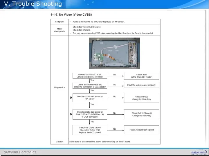
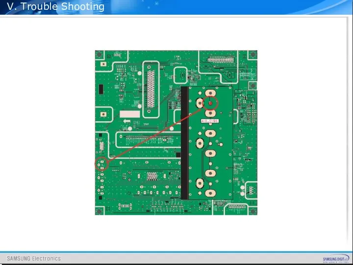
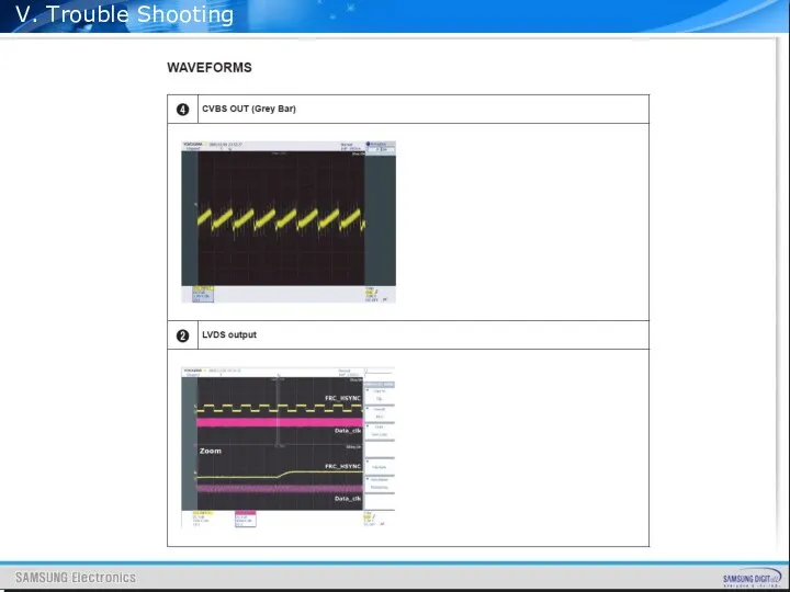
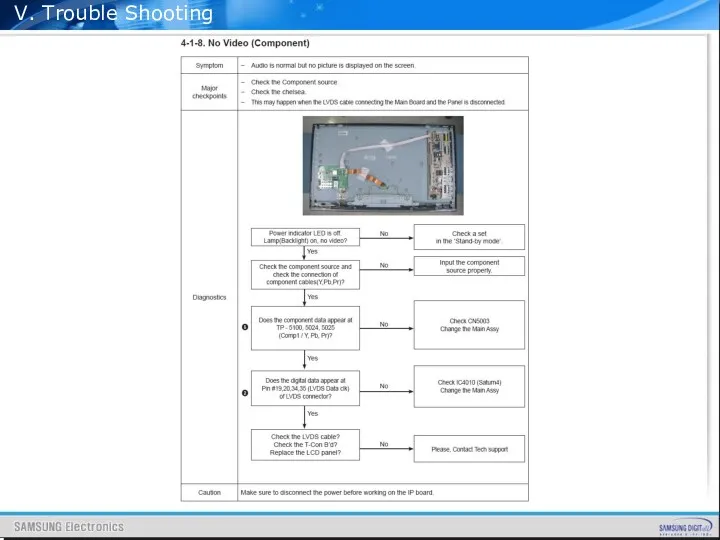
C) Digital Part
It is difficult to check
V. Trouble Shooting
C) Digital Part
It is difficult to check
V. Trouble Shooting
D) Sound Part
Sound block of SEMS12
V. Trouble Shooting
D) Sound Part
Sound block of SEMS12
V. Trouble Shooting
V. Trouble Shooting
V. Trouble Shooting
V. Trouble Shooting
V. Trouble Shooting
V. Trouble Shooting
V. Trouble Shooting
V. Trouble Shooting
V. Trouble Shooting
V. Trouble Shooting

V. Trouble Shooting
V. Trouble Shooting
V. Trouble Shooting
V. Trouble Shooting
V. Trouble Shooting
V. Trouble Shooting
V. Trouble Shooting
V. Trouble Shooting
V. Trouble Shooting
V. Trouble Shooting
V. Trouble Shooting
V. Trouble Shooting
V. Trouble Shooting
V. Trouble Shooting
V. Trouble Shooting
V. Trouble Shooting
V. Trouble Shooting
V. Trouble Shooting
V. Trouble Shooting
V. Trouble Shooting
V. Trouble Shooting
V. Trouble Shooting
V. Trouble Shooting
V. Trouble Shooting
V. Trouble Shooting
V. Trouble Shooting
V. Trouble Shooting
V. Trouble Shooting
V. Trouble Shooting
V. Trouble Shooting
V. Trouble Shooting
V. Trouble Shooting
V. Trouble Shooting
V. Trouble Shooting
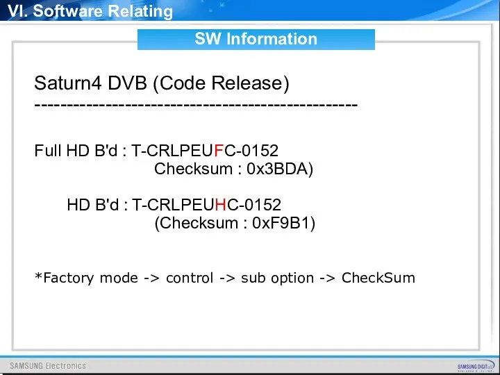
Saturn4 DVB (Code Release)
--------------------------------------------------
Full HD B'd : T-CRLPEUFC-0152
Checksum : 0x3BDA)
--------------------------------------------------
Full HD B'd : T-CRLPEUFC-0152
Checksum : 0x3BDA)
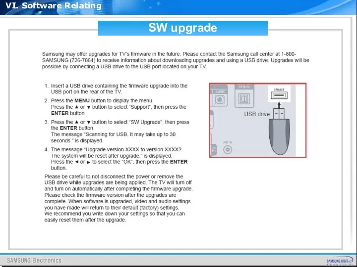
VI. Software Relating
SW upgrade
*Copy the directory to root of USB memory
VI. Software Relating
SW upgrade
*Copy the directory to root of USB memory
VI. Software Relating
SW upgrade
VI. Software Relating
SW upgrade
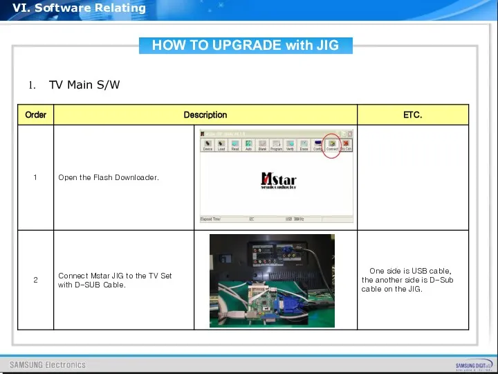
HOW TO UPGRADE with JIG
VI. Software Relating
TV Main S/W
HOW TO UPGRADE with JIG
VI. Software Relating
TV Main S/W
HOW TO UPGRADE with JIG
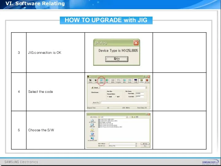
VI. Software Relating
HOW TO UPGRADE with JIG
VI. Software Relating
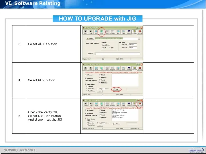
HOW TO UPGRADE with JIG
VI. Software Relating
HOW TO UPGRADE with JIG
VI. Software Relating
Appendix
Feature & Specification
PC timing of FHD & HD
Comparison of User key
Appendix
Feature & Specification
PC timing of FHD & HD
Comparison of User key

1. Feature & Specification
1. Feature & Specification

1. Feature & Specification
1. Feature & Specification
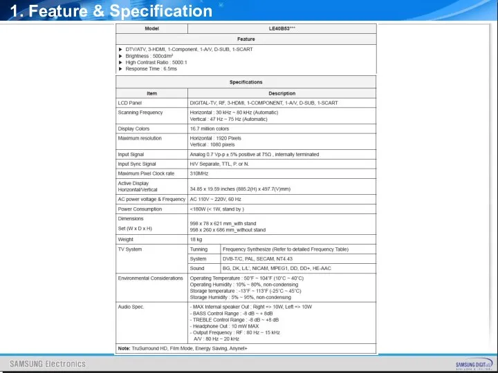
1. Feature & Specification
1. Feature & Specification

1. Feature & Specification
1. Feature & Specification
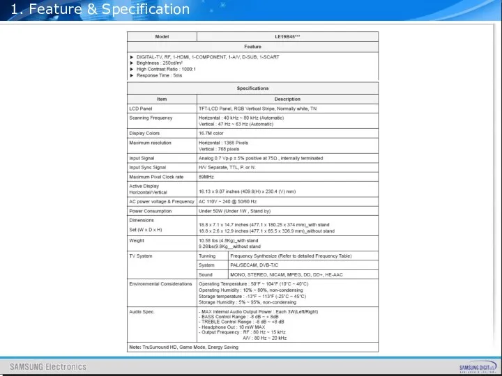
1. Feature & Specification
1. Feature & Specification

1. Feature & Specification
1. Feature & Specification
1. Feature & Specification
1. Feature & Specification

1. Feature & Specification
1. Feature & Specification
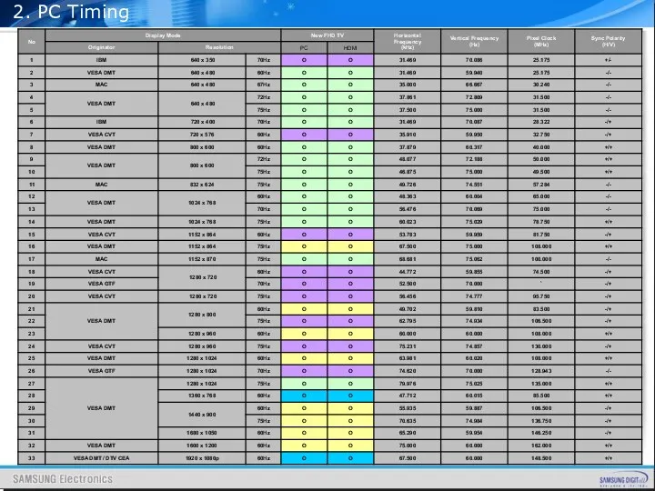
2. PC Timing
2. PC Timing
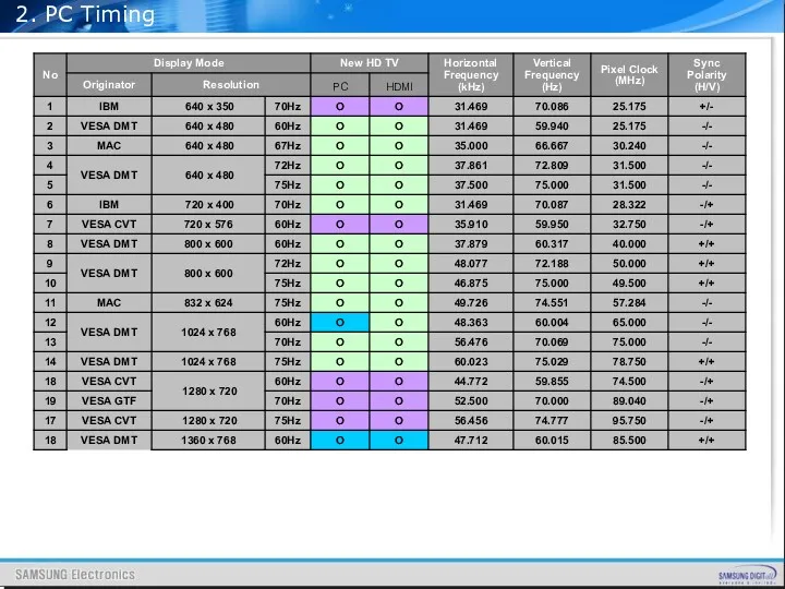
2. PC Timing
2. PC Timing
![Touch Type [B350,B460,B650 models] Tact Switch Type [B450,B530 models] 3. Comparison of User key pad](/_ipx/f_webp&q_80&fit_contain&s_1440x1080/imagesDir/jpg/201012/slide-130.jpg)
Touch Type [B350,B460,B650 models]
Tact Switch Type [B450,B530 models]
3. Comparison of
Touch Type [B350,B460,B650 models]
Tact Switch Type [B450,B530 models]
3. Comparison of
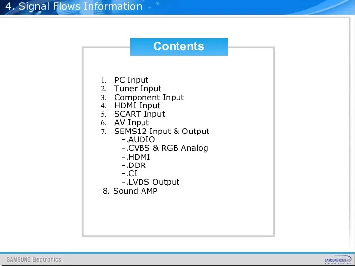
4. Signal Flows Information
Contents
PC Input
Tuner Input
Component Input
HDMI Input
SCART Input
AV Input
SEMS12 Input
4. Signal Flows Information
Contents
PC Input
Tuner Input
Component Input
HDMI Input
SCART Input
AV Input
SEMS12 Input
4. Signal Flows Information
4. Signal Flows Information
4. Signal Flows Information
4. Signal Flows Information
4. Signal Flows Information
4. Signal Flows Information
4. Signal Flows Information
4. Signal Flows Information
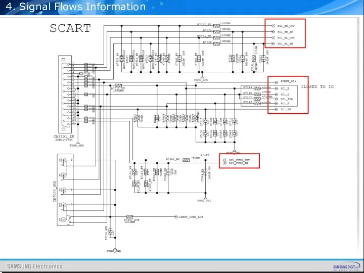
4. Signal Flows Information
4. Signal Flows Information
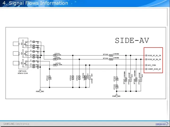
4. Signal Flows Information
4. Signal Flows Information
4. Signal Flows Information
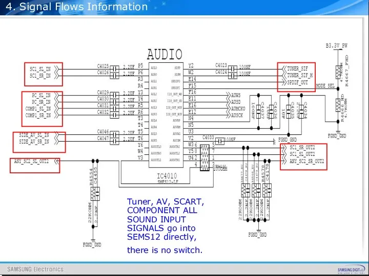
Tuner, AV, SCART, COMPONENT ALL SOUND INPUT SIGNALS
4. Signal Flows Information
Tuner, AV, SCART, COMPONENT ALL SOUND INPUT SIGNALS
4. Signal Flows Information
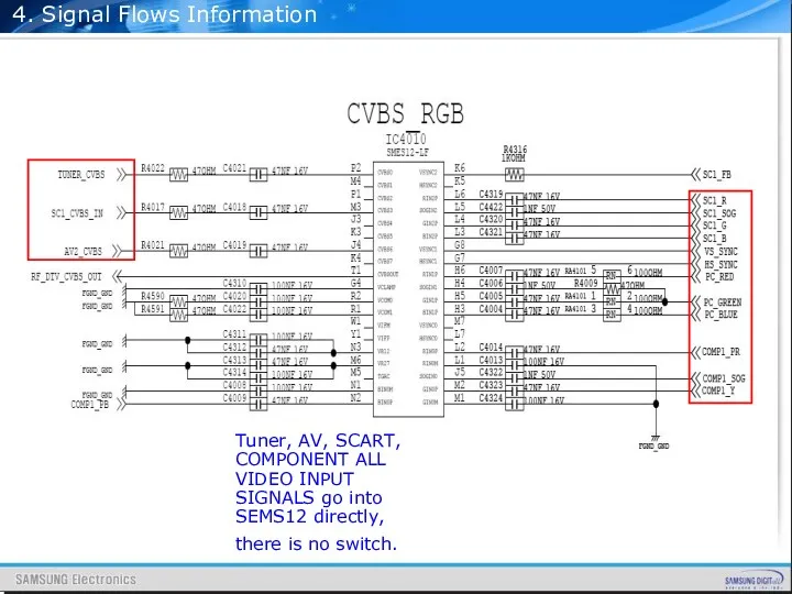
Tuner, AV, SCART, COMPONENT ALL VIDEO INPUT SIGNALS
4. Signal Flows Information
Tuner, AV, SCART, COMPONENT ALL VIDEO INPUT SIGNALS
4. Signal Flows Information
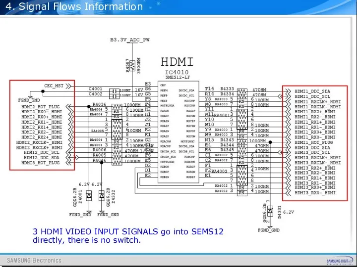
3 HDMI VIDEO INPUT SIGNALS go into SEMS12
4. Signal Flows Information
3 HDMI VIDEO INPUT SIGNALS go into SEMS12
4. Signal Flows Information
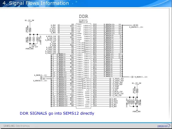
DDR SIGNALS go into SEMS12 directly
4. Signal Flows Information
DDR SIGNALS go into SEMS12 directly
4. Signal Flows Information
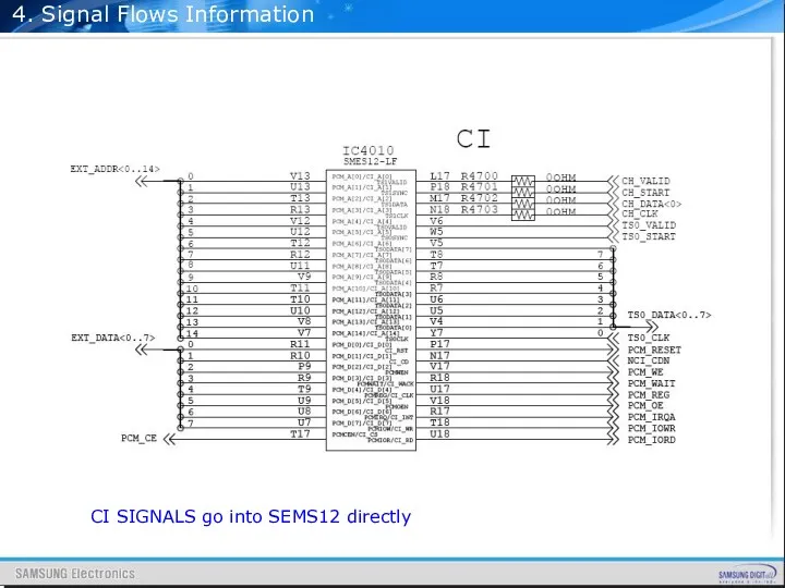
CI SIGNALS go into SEMS12 directly
4. Signal Flows Information
CI SIGNALS go into SEMS12 directly
4. Signal Flows Information
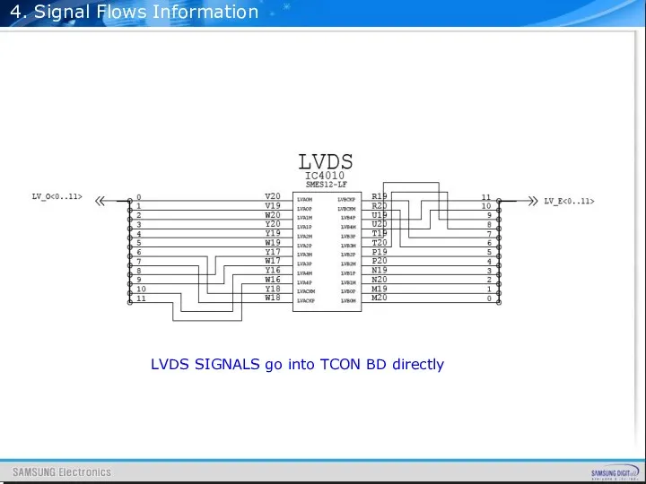
LVDS SIGNALS go into TCON BD directly
4. Signal Flows Information
LVDS SIGNALS go into TCON BD directly
4. Signal Flows Information
SOUND SIGNALS go into NTP3200 from SEMS12 and
4. Signal Flows Information
SOUND SIGNALS go into NTP3200 from SEMS12 and
Contents
32” IP Schematic Diagram
37” IP Schematic Diagram
40” IP Schematic Diagram
46” IP
Contents
32” IP Schematic Diagram
37” IP Schematic Diagram
40” IP Schematic Diagram
46” IP
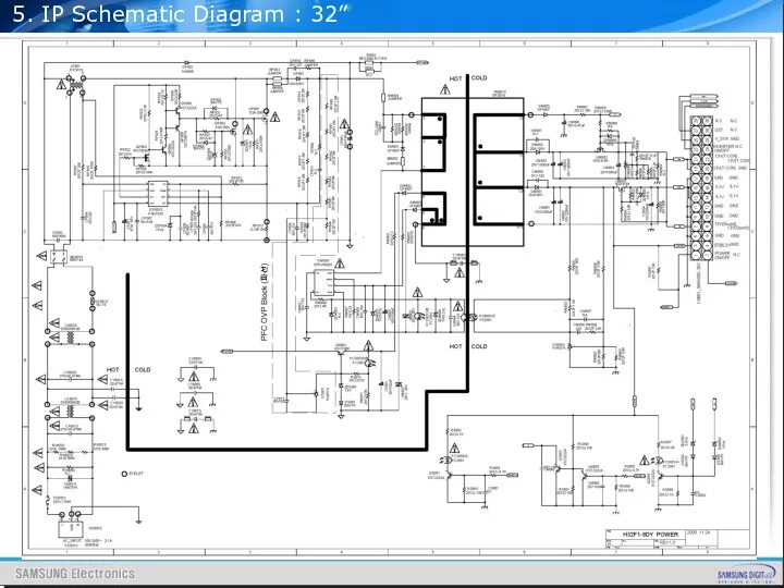
5. IP Schematic Diagram : 32”
5. IP Schematic Diagram : 32”
5. IP Schematic Diagram : 32”
5. IP Schematic Diagram : 32”
5. IP Schematic Diagram : 37”
5. IP Schematic Diagram : 37”
5. IP Schematic Diagram : 37”
5. IP Schematic Diagram : 37”
5. IP Schematic Diagram : 40”
5. IP Schematic Diagram : 40”
5. IP Schematic Diagram : 40”
5. IP Schematic Diagram : 40”
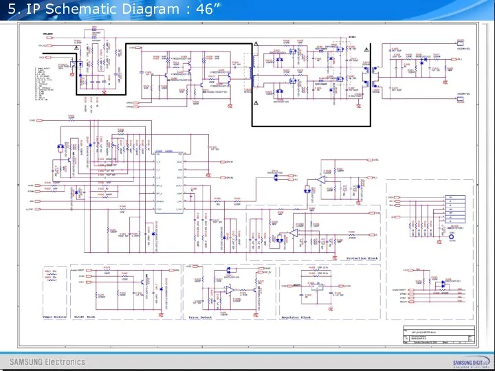
5. IP Schematic Diagram : 46”
5. IP Schematic Diagram : 46”
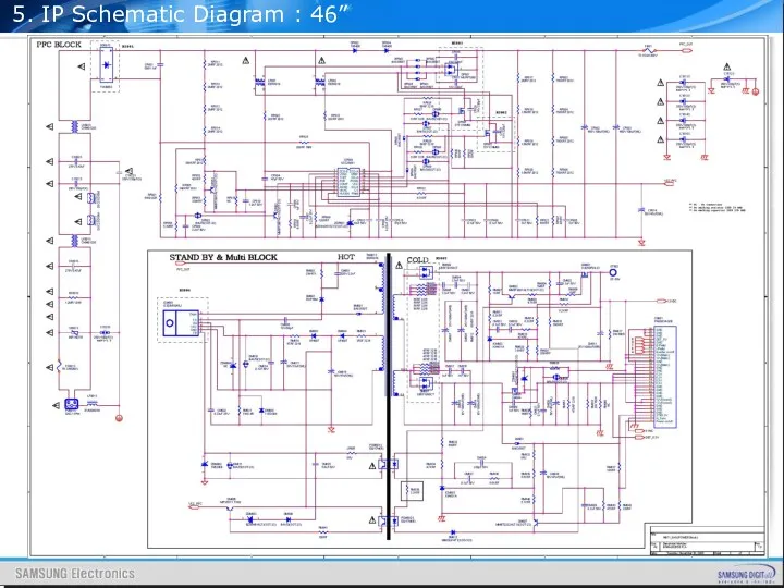
5. IP Schematic Diagram : 46”
5. IP Schematic Diagram : 46”
 300 лет Ломоносову
 Дети войны
 Родительское собрание Добрые трации семьи
 Етапи розробки презентації. Елементи дизайну презентації
 Отчет о работе т/о Хореография за учебный год
 Усиление деревянных конструкций (2)
 Мишка и дни недели
 Классический стиль
 Дизайн штор.
 Музейная антресоль
 Буровые растворы
 Технологическая карта изготовления Кактуса
 Безопасность студентов в стенах образовательного учреждения
 Природная зональность
 Национальная японская кухня
 Ақмола облысы, Целиноград ауданы жағдайында қиярды көшетпен өсіру технологиясы
 Печиво
 Рейтинг подразделений по подаче инициатив ДЦ, ЖДЦ
 Alternative energy
 Объекты управления и их основные свойства. Автоматизированное управление ХТС Лекция 4
 Основные компоненты материнской платы
 Питание в походе
 Мотивационные теории
 Для родителей об адаптации первоклассников
 Введение прикорма
 Мышцы. Мышечная система
 Учебно - методическое пособие:Пресноводные рыбы. Игры и упражнения.
 Производственный менеджмент часть 1 (1)