- Manufacturing and installation of tanks

Содержание
- 2. Manufacture and transportation of rolls of tank bottomsand walls The rules for the installation of vertical
- 3. Vertical cylindrical steel tanks for oil and petroleum products. This standard establishes requirements for the design,
- 4. As the main method of construction of tanks, the method of rolling is adopted, in which
- 5. The panels must be assembled, welded, controlled and rolled up on special installations for rolling, operating
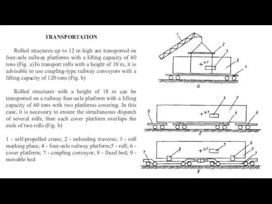
- 6. TRANSPORTATION Rolled structures up to 12 m high are transported on four-axle railway platforms with a
- 7. When loading onto railway platforms, the rolls should be placed on wooden beams and lined with
- 8. Elements of tank structures (coating shields, elements of stiffening rings and support rings, boxes of pontoons
- 9. INSTALLATION OF THE BOTTOM AND THE CENTRAL PART OF THE FLOATING ROOF (PONTOON) Installation of the
- 10. 2) grab the assembled ring of nuts and weld the radial joints, observing the requirements of
- 11. If the traction force of the tractor (tractor winch) is not enough when rolling the rolls,
- 12. BOTTOM ASSEMBLY it can be carried out in two ways: sheet or roll.The bottom is delivered
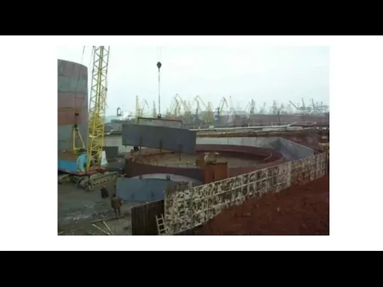
- 13. INSTALLATION SEQUENCE Bottom deployment by two tractors Installation of the central mounting stand by crane Lifting
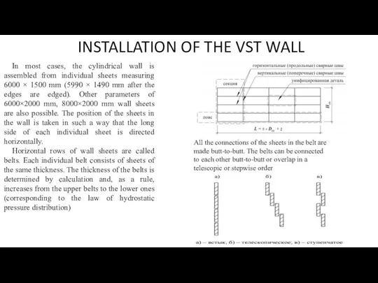
- 15. INSTALLATION OF THE VST WALL In most cases, the cylindrical wall is assembled from individual sheets
- 16. Installation of a cylindrical wall can be carried out in two ways: sheet or roll. The
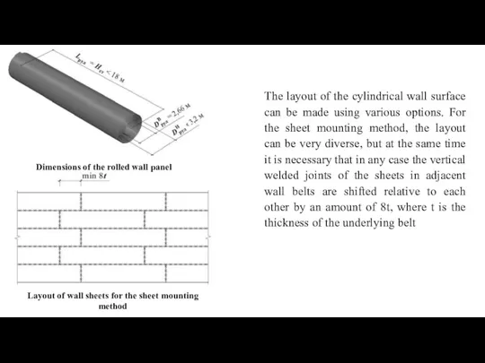
- 17. The layout of the cylindrical wall surface can be made using various options. For the sheet
- 18. For tanks of class II and III, vertical factory and mounting butt joints without displacement are
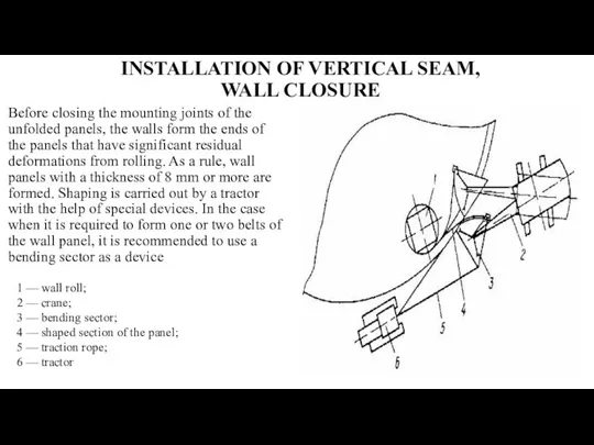
- 19. INSTALLATION OF VERTICAL SEAM, WALL CLOSURE Before closing the mounting joints of the unfolded panels, the
- 20. When forming the panel, a special device is used throughout the height, made of a roll
- 21. When forming the end sections of the wall panels, a mechanized method of straightening by a
- 22. After forming, the overlap is cut off with the cutting of the edge and the joint
- 23. INSTALLATION OF THE ROOF. SEQUENCE. STAGES Low pressure tanks with a fixed roof, depending on the
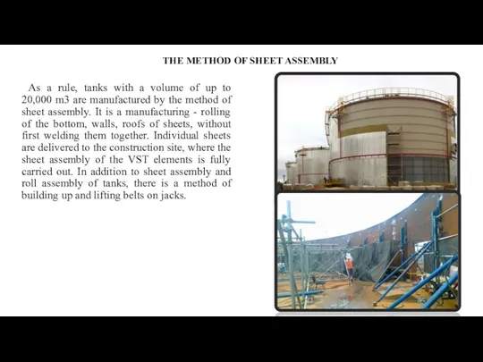
- 24. THE METHOD OF SHEET ASSEMBLY As a rule, tanks with a volume of up to 20,000
- 26. METHODS OF INSTALLATION WELDING OF TANKS - mechanized arc welding with a melting electrode in carbon
- 28. Скачать презентацию
Manufacture and transportation of rolls of tank bottomsand walls
The rules for
Manufacture and transportation of rolls of tank bottomsand walls
The rules for
Vertical cylindrical steel tanks for oil and petroleum products.
This standard establishes
Vertical cylindrical steel tanks for oil and petroleum products.
This standard establishes
As the main method of construction of tanks, the method of
As the main method of construction of tanks, the method of
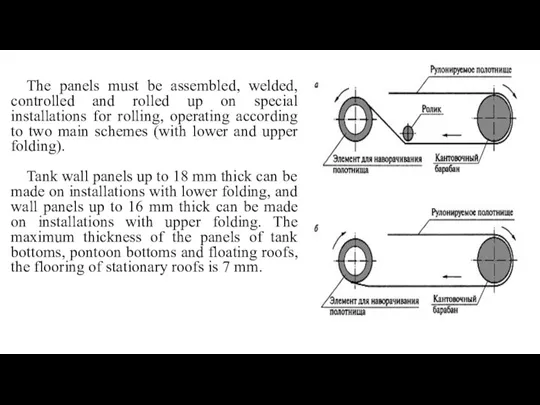
The panels must be assembled, welded, controlled and rolled up on
The panels must be assembled, welded, controlled and rolled up on
TRANSPORTATION
Rolled structures up to 12 m high are transported on four-axle
TRANSPORTATION
Rolled structures up to 12 m high are transported on four-axle
When loading onto railway platforms, the rolls should be placed on
When loading onto railway platforms, the rolls should be placed on
Elements of tank structures (coating shields, elements of stiffening rings and
Elements of tank structures (coating shields, elements of stiffening rings and
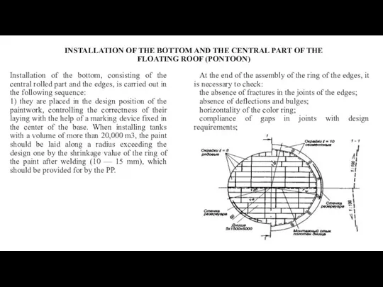
INSTALLATION OF THE BOTTOM AND THE CENTRAL PART OF THE FLOATING
INSTALLATION OF THE BOTTOM AND THE CENTRAL PART OF THE FLOATING
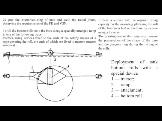
2) grab the assembled ring of nuts and weld the radial
2) grab the assembled ring of nuts and weld the radial
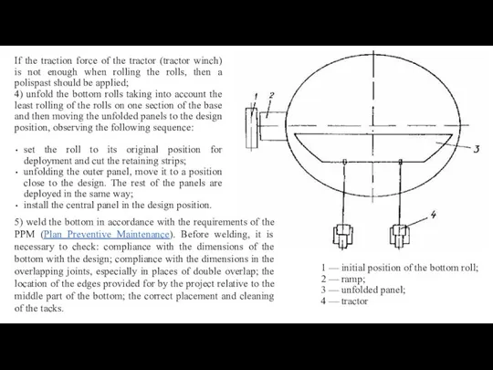
If the traction force of the tractor (tractor winch) is not
If the traction force of the tractor (tractor winch) is not
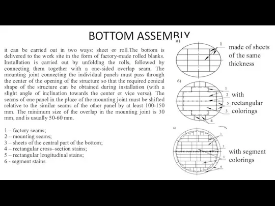
BOTTOM ASSEMBLY
it can be carried out in two ways: sheet or
BOTTOM ASSEMBLY
it can be carried out in two ways: sheet or
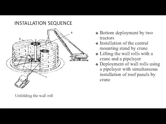
INSTALLATION SEQUENCE
Bottom deployment by two tractors
Installation of the central mounting stand
INSTALLATION SEQUENCE
Bottom deployment by two tractors
Installation of the central mounting stand
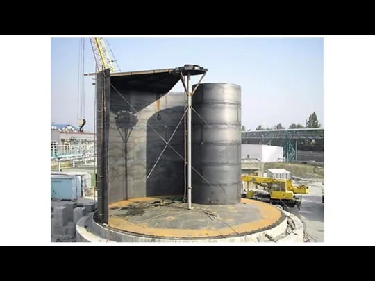
INSTALLATION OF THE VST WALL
In most cases, the cylindrical wall is
INSTALLATION OF THE VST WALL
In most cases, the cylindrical wall is
Installation of a cylindrical wall can be carried out in two
Installation of a cylindrical wall can be carried out in two
The layout of the cylindrical wall surface can be made using
The layout of the cylindrical wall surface can be made using
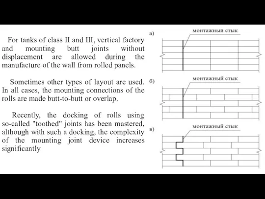
For tanks of class II and III, vertical factory and mounting
For tanks of class II and III, vertical factory and mounting
INSTALLATION OF VERTICAL SEAM, WALL CLOSURE
Before closing the mounting joints of
INSTALLATION OF VERTICAL SEAM, WALL CLOSURE
Before closing the mounting joints of
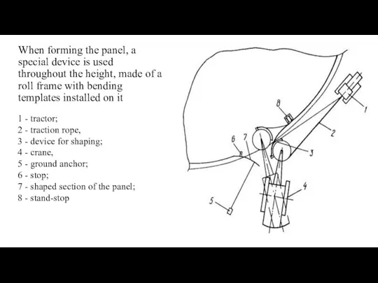
When forming the panel, a special device is used throughout the
When forming the panel, a special device is used throughout the
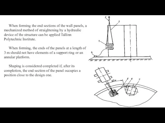
When forming the end sections of the wall panels, a mechanized
When forming the end sections of the wall panels, a mechanized
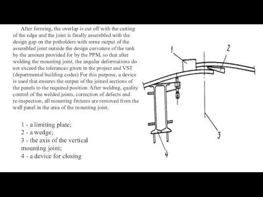
After forming, the overlap is cut off with the cutting of
After forming, the overlap is cut off with the cutting of
INSTALLATION OF THE ROOF. SEQUENCE. STAGES
Low pressure tanks with a fixed
INSTALLATION OF THE ROOF. SEQUENCE. STAGES
Low pressure tanks with a fixed
THE METHOD OF SHEET ASSEMBLY
As a rule, tanks with a volume
THE METHOD OF SHEET ASSEMBLY
As a rule, tanks with a volume
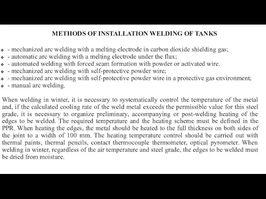
METHODS OF INSTALLATION WELDING OF TANKS
- mechanized arc welding with a
METHODS OF INSTALLATION WELDING OF TANKS
- mechanized arc welding with a
 Школа нового покоління презентує!
 Construction
 Письмо от деда Мороза
 Фазы медиации: прошлое-настоящее-будущее
 Теория личности
 Профилактика и коррекция дисграфии на почве нарушения фонемного распознавания. Дифференциация Б-Т.
 ИЗ ИСТОРИИ ОЛИМПИЙСКИХ ИГР.
 Урок 29-2
 Методика ортопедического лечения литыми вкладками
 Презентация Путешествие Лунтика по планете Земля
 исследовательская работа Зачем ежу яблоки
 Производство чугуна и стали
 Тест по информатике Файл. Вариант 2. 8 класс
 Машины для внесения удобрений в почву и защиты растений
 математические фокусы
 Идея развития органического мира. Основные положения теории Чарльза Дарвина об эволюции органического мира
 Обобщающий урок по теме: Признаки параллельности двух прямых
 Экономика знаний
 Возрастные особенности нервной системы юношеского возраста
 Япония - страна восходящего Солнца. Презентация.
 Искусство Владимиро-Суздальской Руси
 Сравнительная характеристика методов нейтронного каротажа для определения водонасыщенной пористости
 Тамақтанудың адам ағзасы үшін маңызы
 Урок вежливости
 Условное наклонение глагола. 6 класс
 Кроссворды на темуИзвестных женщин имена
 Плотность вещества. 7 класс
 Персонажи славянской мифологии, связанные с повседневной жизнью людей