- Мікропроцесорна техніка (лекція 5)

Содержание
- 2. PSoC@3/5 IDAC8 PSoC Creator 4.2 Designing with PSoC 3/5
- 3. Модулі PSoC@3/5
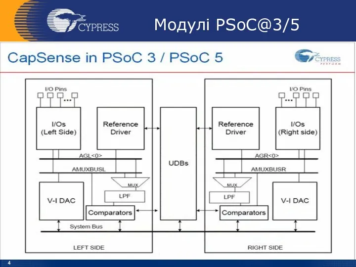
- 4. Модулі PSoC@3/5
- 5. IDAC8 Block Diagram IDAC8
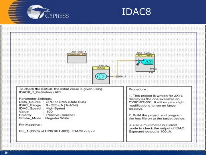
- 6. Lab_5 IDAC8
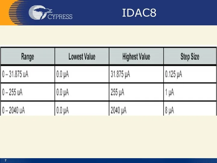
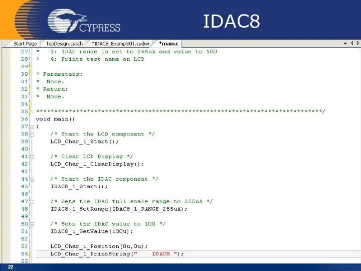
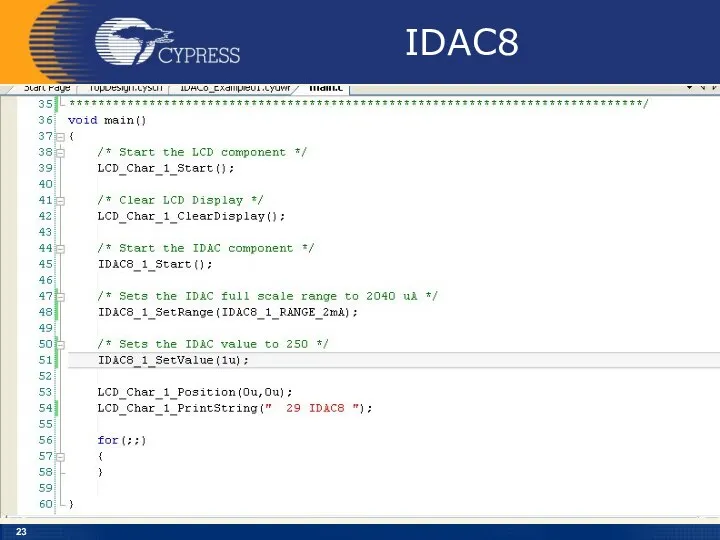
- 7. IDAC8
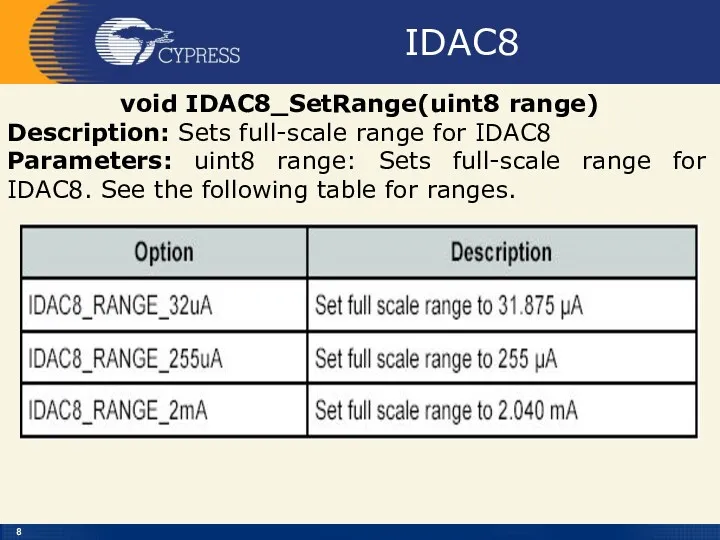
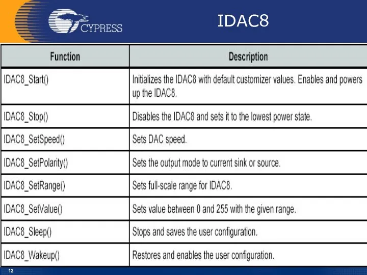
- 8. IDAC8 void IDAC8_SetRange(uint8 range) Description: Sets full-scale range for IDAC8 Parameters: uint8 range: Sets full-scale range
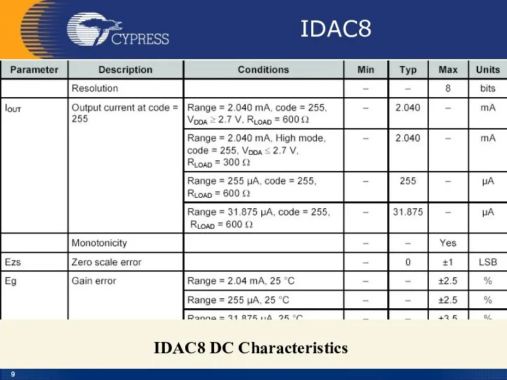
- 9. IDAC8 IDAC8 DC Characteristics
- 10. IDAC8 Iout – Analog The Iout terminal, the terminal on the right side of the symbol,
- 11. IDAC8 ipolarity – Input* The ipolarity input is an optional signal input pin. This pin can
- 12. IDAC8
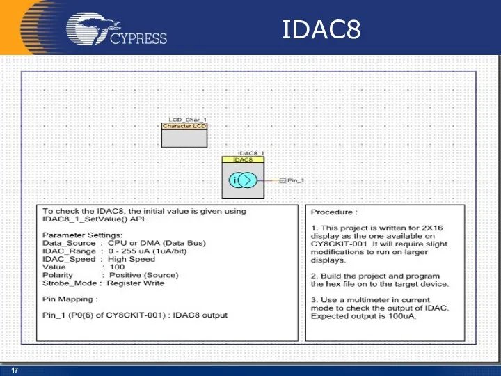
- 13. IDAC8 Follow the below steps to do this: The Lab already has the LCD Character component
- 14. Creator
- 15. File – New - Projekt
- 16. Empty PSoC 3 Design
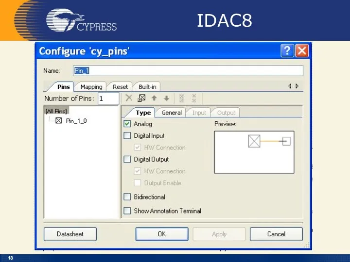
- 17. IDAC8
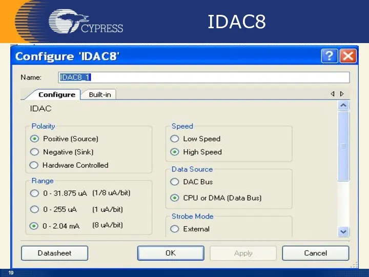
- 18. IDAC8
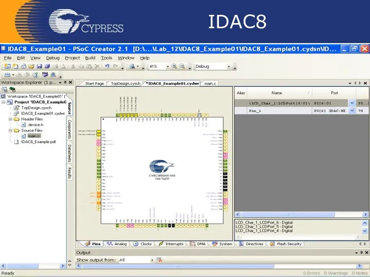
- 19. IDAC8
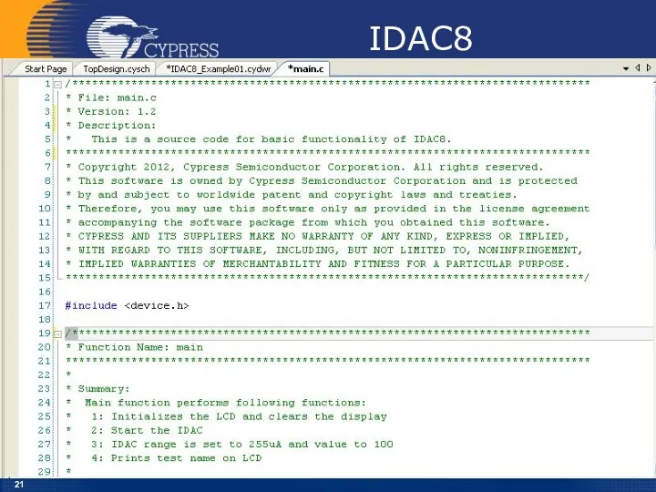
- 20. IDAC8
- 21. IDAC8
- 22. IDAC8
- 23. IDAC8
- 24. IDAC8 Overview: Activate and use the IDAC8 on the DVK board and output the results to
- 25. IDAC8 Зняти вольт-амперну характеристику напівпровідникового діода
- 26. IDAC8
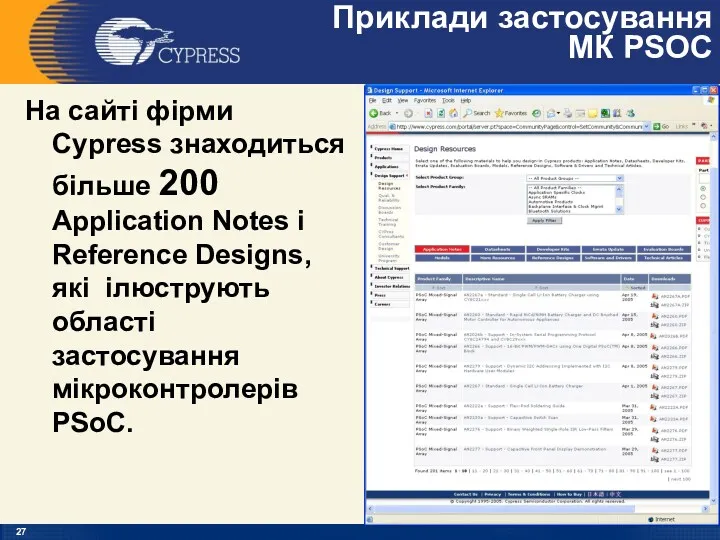
- 27. Приклади застосування МК PSOC На сайті фірми Cypress знаходиться більше 200 Application Notes і Reference Designs,
- 29. Скачать презентацию
PSoC@3/5
IDAC8
PSoC Creator 4.2
Designing with PSoC 3/5
PSoC@3/5
IDAC8
PSoC Creator 4.2
Designing with PSoC 3/5
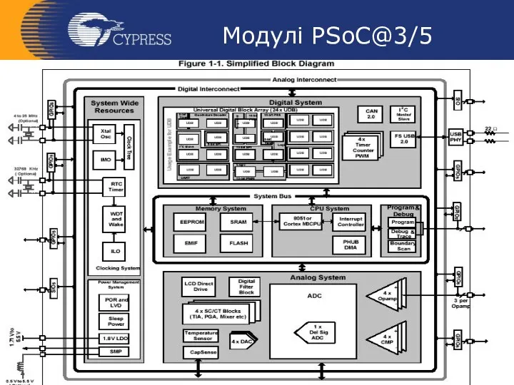
Модулі PSoC@3/5
Модулі PSoC@3/5
Модулі PSoC@3/5
Модулі PSoC@3/5
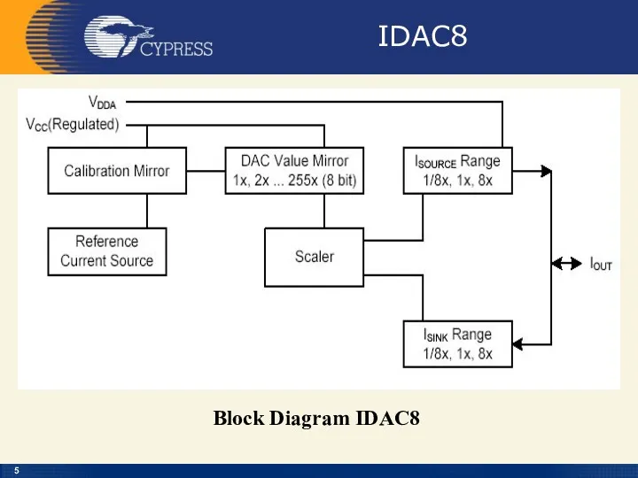
IDAC8
Block Diagram IDAC8
IDAC8
Block Diagram IDAC8
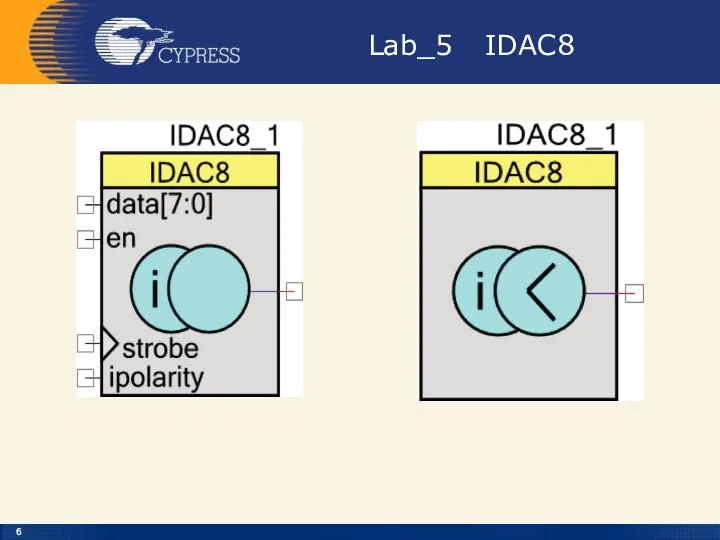
Lab_5 IDAC8
Lab_5 IDAC8
IDAC8
IDAC8
IDAC8
void IDAC8_SetRange(uint8 range)
Description: Sets full-scale range for IDAC8
Parameters: uint8 range:
IDAC8
void IDAC8_SetRange(uint8 range)
Description: Sets full-scale range for IDAC8
Parameters: uint8 range:
IDAC8
IDAC8 DC Characteristics
IDAC8
IDAC8 DC Characteristics
IDAC8
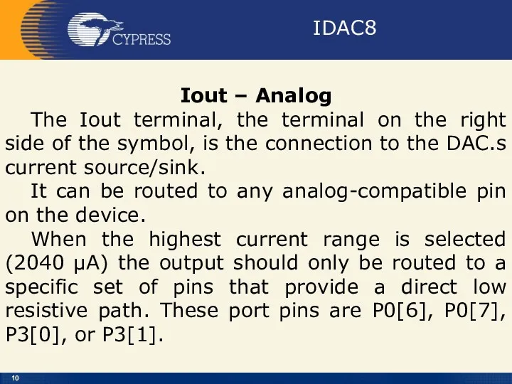
Iout – Analog
The Iout terminal, the terminal on the right
IDAC8
Iout – Analog
The Iout terminal, the terminal on the right
IDAC8
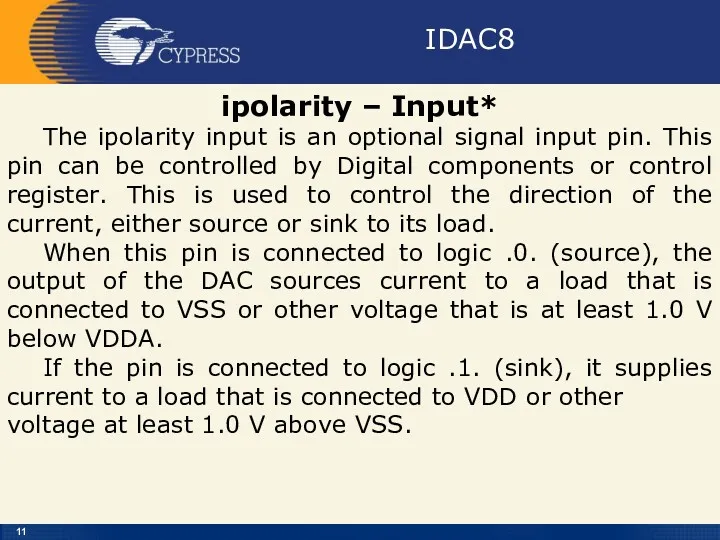
ipolarity – Input*
The ipolarity input is an optional signal input
IDAC8
ipolarity – Input*
The ipolarity input is an optional signal input
IDAC8
IDAC8
IDAC8
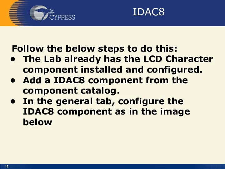
Follow the below steps to do this:
The Lab already has
IDAC8
Follow the below steps to do this:
The Lab already has
Creator
Creator
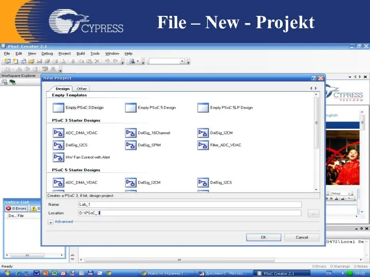
File – New - Projekt
File – New - Projekt
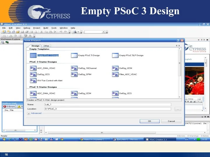
Empty PSoC 3 Design
Empty PSoC 3 Design
IDAC8
IDAC8
IDAC8
IDAC8
IDAC8
IDAC8
IDAC8
IDAC8
IDAC8
IDAC8
IDAC8
IDAC8
IDAC8
IDAC8
IDAC8
Overview:
Activate and use
the IDAC8 on the DVK board
and
IDAC8
Overview:
Activate and use
the IDAC8 on the DVK board
and
IDAC8
Зняти
вольт-амперну характеристику
напівпровідникового діода
IDAC8
Зняти
вольт-амперну характеристику
напівпровідникового діода
IDAC8
IDAC8
Приклади застосування
МК PSOC
На сайті фірми Cypress знаходиться більше 200 Application
Приклади застосування
МК PSOC
На сайті фірми Cypress знаходиться більше 200 Application
 Современные средства поражения
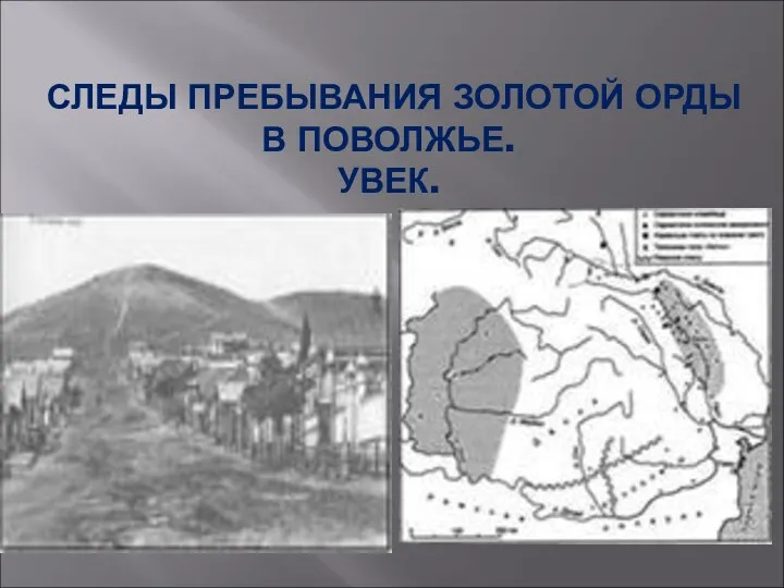 Золотая Орда В Поволжье .Увек.
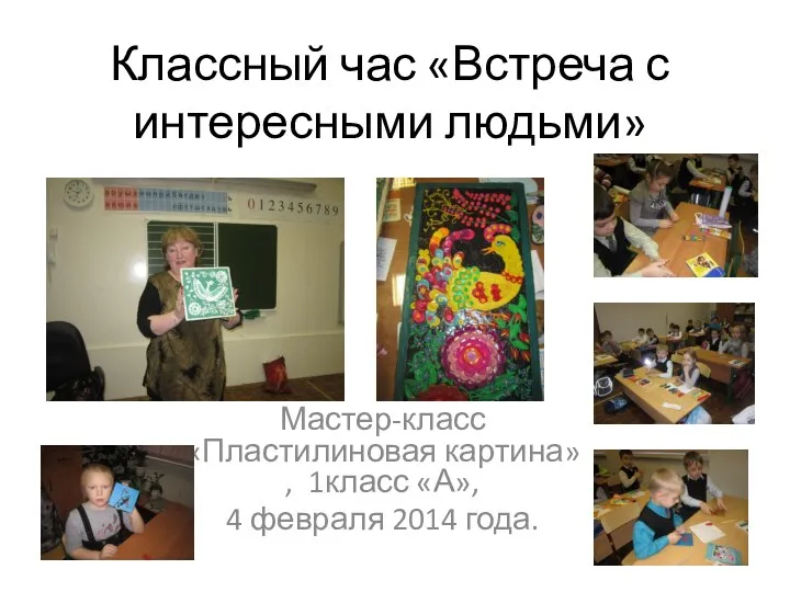 Встреча с интересными людьми.
 Unicorn sight word match. Graphics by prettygrafik design
 Роль страховой медицинской организации в повышении доступности медицинской помощи
 Мы живём среди друзей
 Развитие детского аутизма и аутистические черты личности
 Этапы компьютерного моделирования
 группа раннего развития
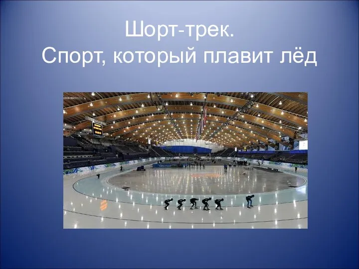 Презентации по зимним видам спорта
 Классный час Научите свое сердце добру
 Презентация Теоретические основы работы с детьми с задержкой психического развития
 Учение о биосфере. (Лекция 2)
 МОЙ ЛУЧШИЙ ДРУГ - ПАПА
 Бабушкин сундук ( Әбиемнең сандыгы)
 Жаңадан шыққан техникалар
 Скакалочка. Игра
 Чтение №104. Сказки А. С. Пушкина
 Методические рекомендации по организации выполнения и защиты, оформлению выпускной квалификационной работы
 Классный час Мое Приморье
 Устная часть ЕГЭ по английскому языку
 Праздники народов россии
 Профилактика инфекционных болезней и эпидемий. Карантинные инфекции и особо опасные инфекции
 Лямблиоз у детей
 Работа с ритмом на уроке сольфеджио
 Развитие мелкой моторики через различные виды деятельности
 Дослідження та удосконалення САК температурним режимом зерносушарки на хлібокомбінаті
 Пожарная безопасность для дошкольников 5-7 лет