- MС165 maintenance. Instruction

Содержание
- 2. TABLE OF CONTENTS 1 Overview MC165 1.1 About MC165 Phone 1.2 Distribution of the mainboard components
- 3. 1 Overview MC165 1.1 About MC165 Phone MC165 mainboard is based on the MTK platform designed
- 4. 1.2 Distribution of the mainboard components
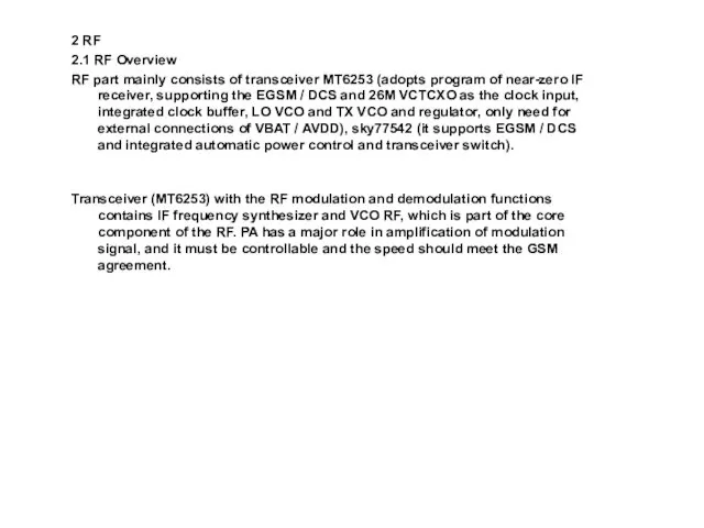
- 6. 2 RF 2.1 RF Overview RF part mainly consists of transceiver MT6253 (adopts program of near-zero
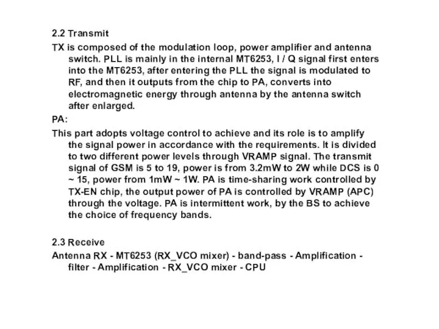
- 7. 2.2 Transmit TX is composed of the modulation loop, power amplifier and antenna switch. PLL is
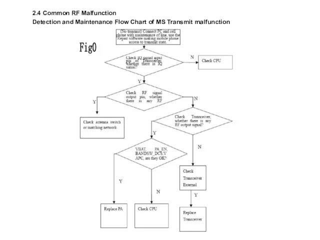
- 8. 2.4 Common RF Malfunction Detection and Maintenance Flow Chart of MS Transmit malfunction Fig0
- 9. Fig0
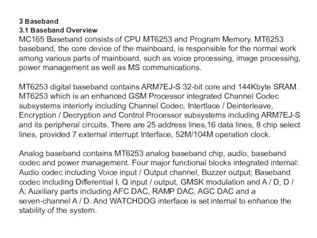
- 10. 3 Baseband 3.1 Baseband Overview MC165 Baseband consists of CPU MT6253 and Program Memory. MT6253 baseband,
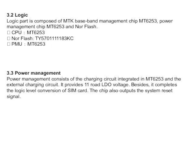
- 11. 3.2 Logic Logic part is composed of MTK base-band management chip MT6253, power management chip MT6253
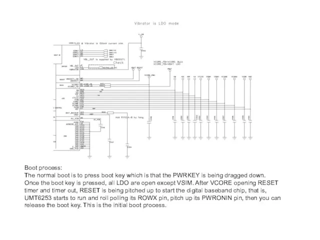
- 12. Boot process: The normal boot is to press boot key which is that the PWRKEY is
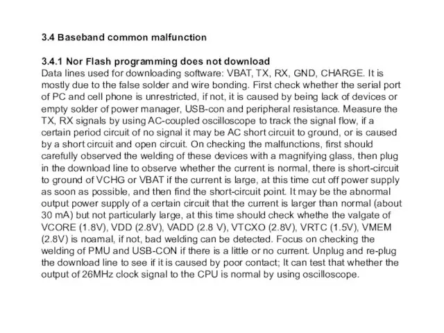
- 13. 3.4 Baseband common malfunction 3.4.1 Nor Flash programming does not download Data lines used for downloading
- 14. 3.4.2 Detection and Maintenance Flow Chart of No download malfunction
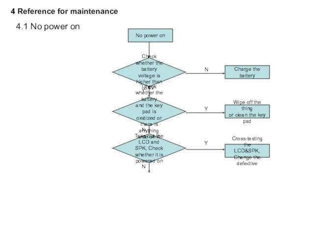
- 15. 4.1 No power on Take out the LCD and SPK, Check whether it is powered on
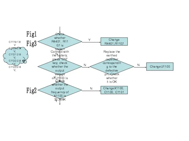
- 16. Check whether R4401,R1107 is broken Change R4401,R1107 Replace the earthed capacitor corresponding to the defective pin,
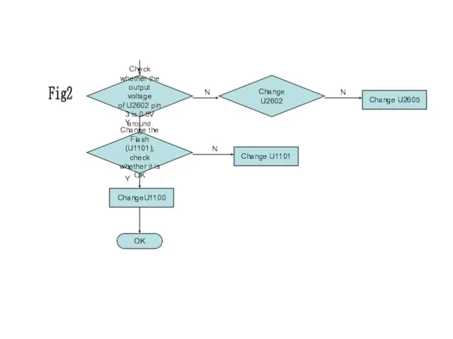
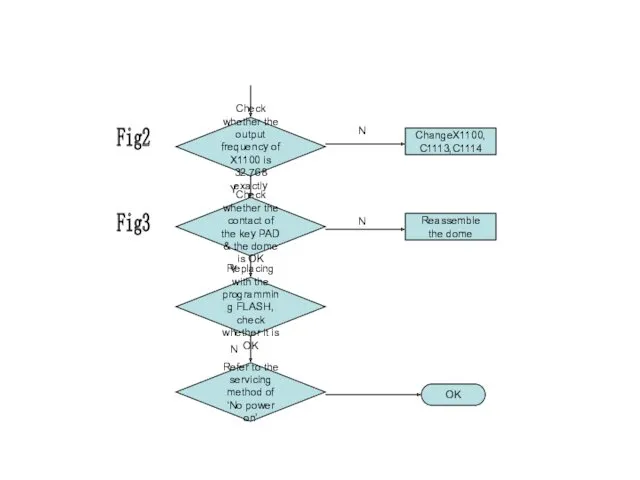
- 17. Change the Flash (U1101), check whether it is OK ChangeU1100 OK Y Check whether the output
- 18. Fig1
- 19. Fig2
- 20. 4.2 Shut off automatically Shut off automatically D/L the latest software, Check whether it is OK
- 21. Check whether the contact of the key PAD & the dome is OK Reassemble the dome
- 22. Fig3
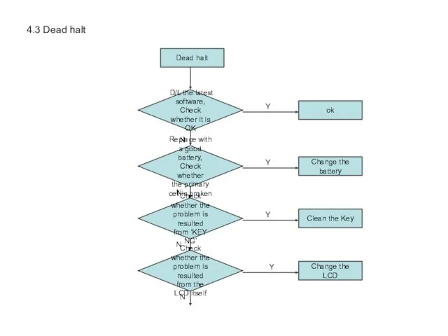
- 23. 4.3 Dead halt Dead halt D/L the latest software, Check whether it is OK Replace with
- 24. Check whether the contact of the key PAD & the dome is OK Reassemble the dome
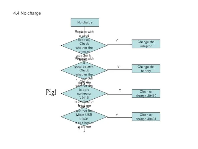
- 25. 4.4 No charge No charge Replace with a good battery, Check whether the primary cell is
- 26. Check whether there is broken of U1102, R1105,C1131 Change the defective Plug in, Check whether it
- 27. 4.5 Quantity of electricity faulty detection Quantity of electricity faulty detection Replace with a good battery,
- 28. 4.6 No display No display Download the latest Software, Check whether it is OK ok N
- 29. Fig4
- 30. 4.7 LED NG (on the LCD) LED NG (LCD) Check whether the LCD is broken Change
- 31. 4.8 LED NG (on the key board) LED NG (key) Check whether the LED of the
- 32. 4.9 Key NG Key NG Check whether the metal dome is oxidized or broken Change the
- 33. Check whether the D4417~D4420 D4429~D4435 is broken Change the defective OK Change CPU(U1100) Fig3 N Y
- 34. 4.10 No ring No ring Check whether the SPK is void-welded or broken Re-weld or change
- 35. OK Check whether it is high on pad of R3357 Check U3300 Y N Check whether
- 36. Fig5
- 37. Fig6
- 38. 4.11 No receiving voice No receiving voice Check whether the REC PAD is oxidized or broken
- 39. Fig7
- 40. 4.12 No sending voice or the voice is small No sending voice or a small voice
- 41. check whether there is anyone broken of C3308~3312, B3300, B3301,D3301, D3302 Change the defective OK Change
- 42. Fig8
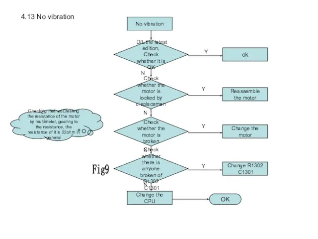
- 43. 4.13 No vibration No vibration Check whether the motor is locked by displacement Reassemble the motor
- 44. Fig9
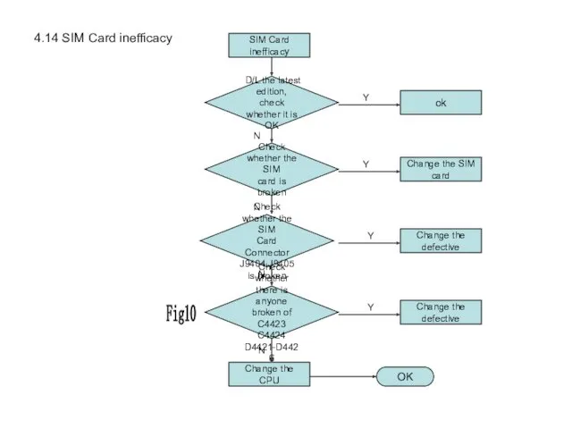
- 45. 4.14 SIM Card inefficacy SIM Card inefficacy Check whether the SIM card is broken Change the
- 46. Fig10
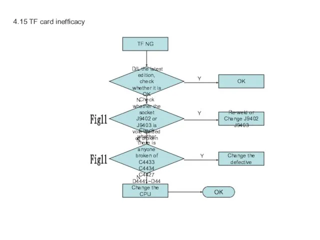
- 47. 4.15 TF card inefficacy TF NG Check whether the socket J9402 or J9403 is void-welded or
- 48. Fig11
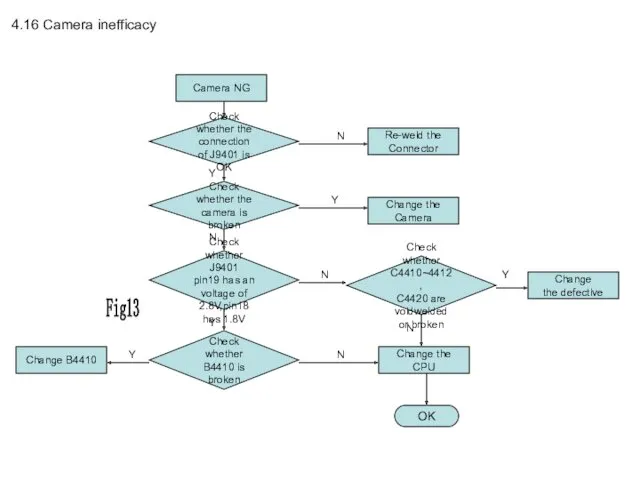
- 49. 4.16 Camera inefficacy Camera NG Check whether the camera is broken Change the Camera Check whether
- 50. Fig13
- 51. 4.17 Bluetooth circuit(MT6612) Bluetooth is a design feature of this cellphone. It is with a matching
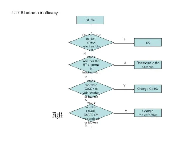
- 52. 4.17 Bluetooth inefficacy BT NG Check whether the BT antenna is touched well Reassemble the antenna
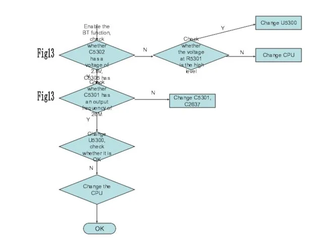
- 53. Enable the BT function, check whether C5302 has a voltage of 2.8V, C5305 has 1.2V Change
- 54. Fig13
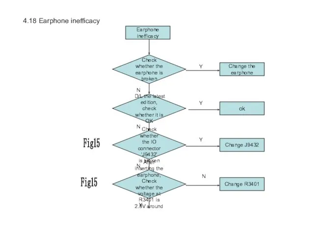
- 55. 4.18 Earphone inefficacy Earphone inefficacy Check whether the IO connector ‘J9432’ is broken Change J9432 Check
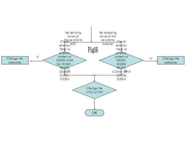
- 56. Check whether there is anyone broken of C3300~C3304, R3301- R3303, B3306, C3351, C3320 OK Change the
- 57. Fig15
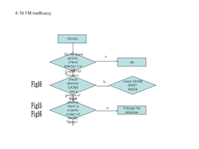
- 58. 4.19 FM inefficacy FM NG Enable FM function, check whether C4308 has a voltage of 2.8V
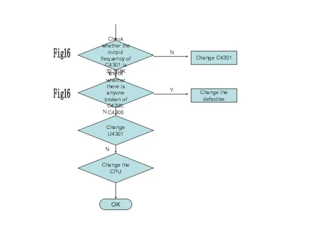
- 59. Check whether the output frequency of C4301 is 32.768K Change C4301 OK Change the CPU Change
- 60. Fig16
- 62. Скачать презентацию
TABLE OF CONTENTS
1 Overview MC165
1.1 About MC165 Phone
1.2 Distribution of the
TABLE OF CONTENTS 1 Overview MC165 1.1 About MC165 Phone 1.2 Distribution of the
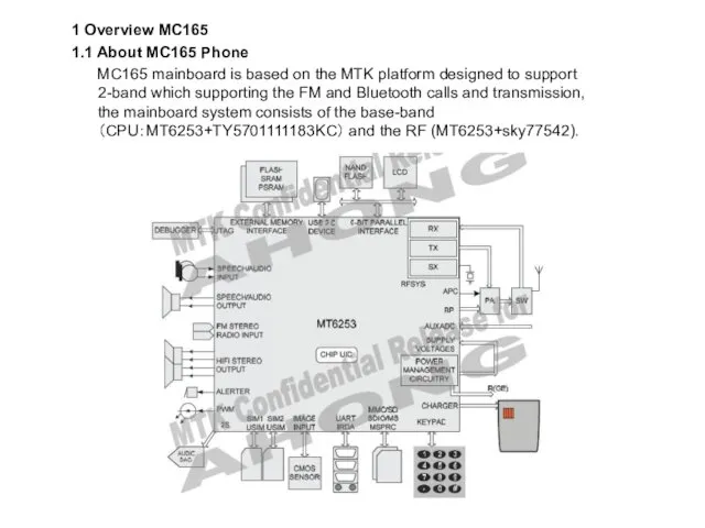
1 Overview MC165
1.1 About MC165 Phone
MC165 mainboard is based on
1 Overview MC165
1.1 About MC165 Phone
MC165 mainboard is based on
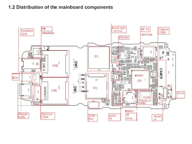
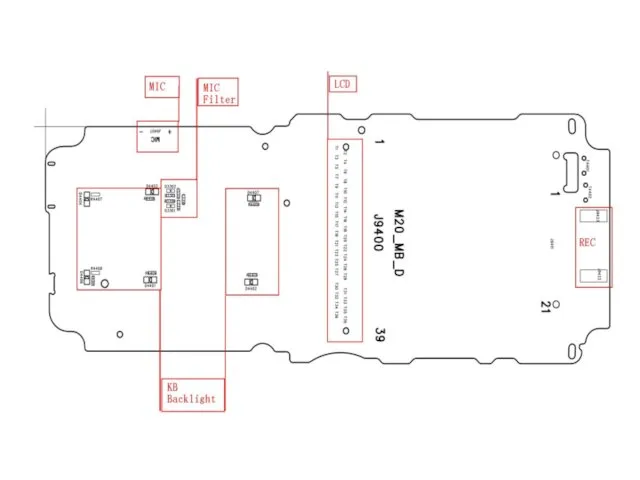
1.2 Distribution of the mainboard components
1.2 Distribution of the mainboard components
2 RF
2.1 RF Overview
RF part mainly consists of transceiver MT6253 (adopts
2 RF
2.1 RF Overview
RF part mainly consists of transceiver MT6253 (adopts
2.2 Transmit
TX is composed of the modulation loop, power amplifier and
2.2 Transmit
TX is composed of the modulation loop, power amplifier and
2.4 Common RF Malfunction
Detection and Maintenance Flow Chart of MS Transmit
2.4 Common RF Malfunction
Detection and Maintenance Flow Chart of MS Transmit
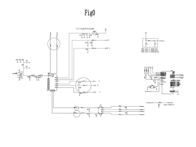
Fig0
Fig0
3 Baseband
3.1 Baseband Overview
MC165 Baseband consists of CPU MT6253 and Program
3 Baseband
3.1 Baseband Overview
MC165 Baseband consists of CPU MT6253 and Program
3.2 Logic
Logic part is composed of MTK base-band management chip MT6253,
3.2 Logic
Logic part is composed of MTK base-band management chip MT6253,
Boot process:
The normal boot is to press boot key which is
Boot process:
The normal boot is to press boot key which is
3.4 Baseband common malfunction
3.4.1 Nor Flash programming does not download
Data lines
3.4 Baseband common malfunction
3.4.1 Nor Flash programming does not download
Data lines
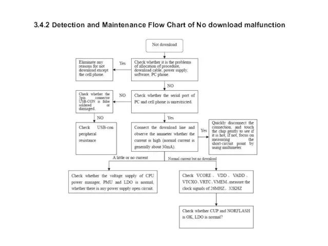
3.4.2 Detection and Maintenance Flow Chart of No download malfunction
3.4.2 Detection and Maintenance Flow Chart of No download malfunction
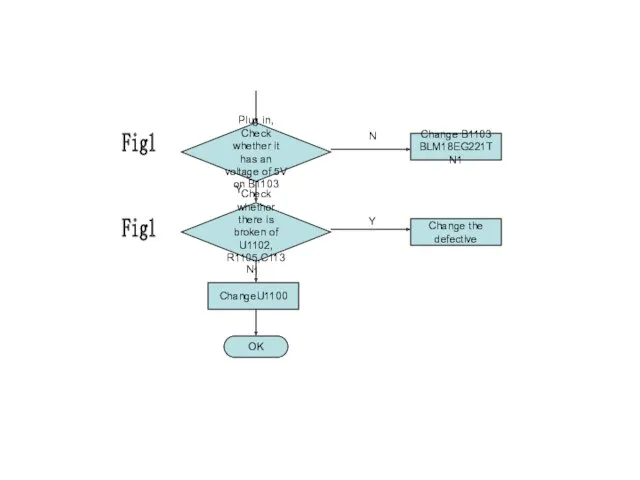
4.1 No power on
Take out the LCD and
SPK, Check whether it
4.1 No power on
Take out the LCD and
SPK, Check whether it
Check whether
R4401,R1107 is
broken
Change R4401,R1107
Replace the earthed capacitor
corresponding to the
defective pin, Check
Check whether
R4401,R1107 is
broken
Change R4401,R1107
Replace the earthed capacitor
corresponding to the
defective pin, Check
Change the Flash (U1101),
check whether it is OK
ChangeU1100
OK
Y
Check whether the output
Change the Flash (U1101),
check whether it is OK
ChangeU1100
OK
Y
Check whether the output
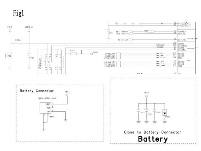
Fig1
Fig1
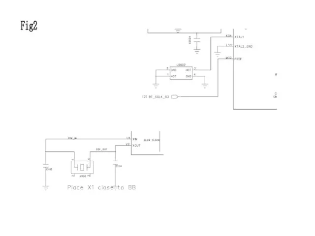
Fig2
Fig2
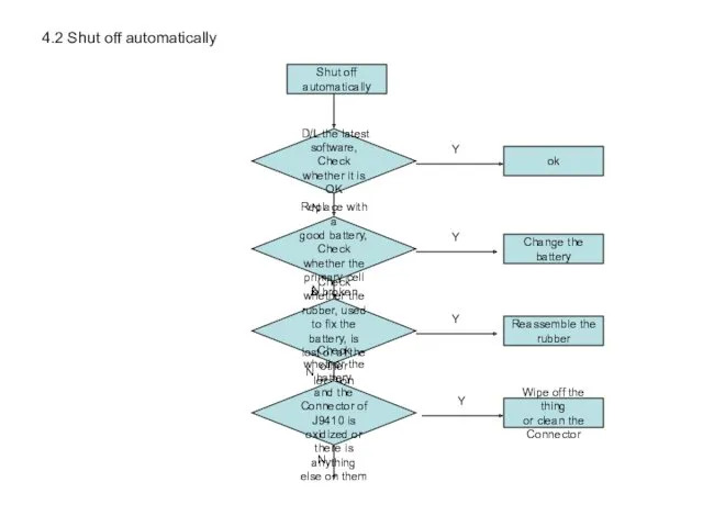
4.2 Shut off automatically
Shut off automatically
D/L the latest software,
Check whether it
4.2 Shut off automatically
Shut off automatically
D/L the latest software,
Check whether it
Check whether the contact of
the key PAD & the dome is
Check whether the contact of
the key PAD & the dome is
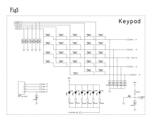
Fig3
Fig3
4.3 Dead halt
Dead halt
D/L the latest software,
Check whether it is OK
Replace
4.3 Dead halt
Dead halt
D/L the latest software,
Check whether it is OK
Replace
Check whether the contact of
the key PAD & the dome is
Check whether the contact of
the key PAD & the dome is
4.4 No charge
No charge
Replace with a
good battery, Check
whether the
primary cell is
4.4 No charge
No charge
Replace with a
good battery, Check
whether the
primary cell is
Check whether there is broken of
U1102, R1105,C1131
Change the defective
Plug in, Check
Check whether there is broken of
U1102, R1105,C1131
Change the defective
Plug in, Check
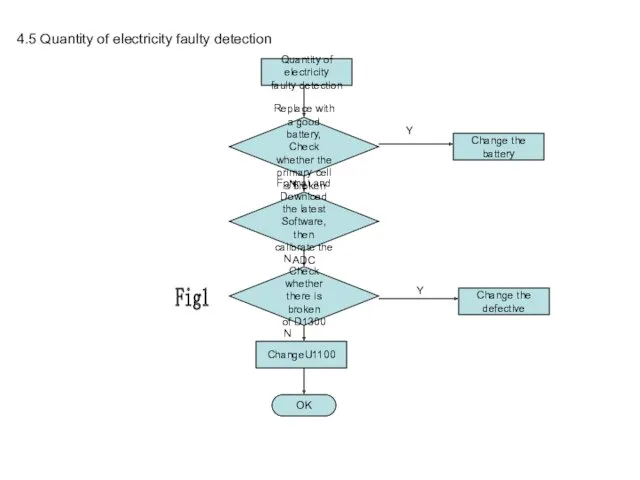
4.5 Quantity of electricity faulty detection
Quantity of electricity
faulty detection
Replace with a
4.5 Quantity of electricity faulty detection
Quantity of electricity
faulty detection
Replace with a
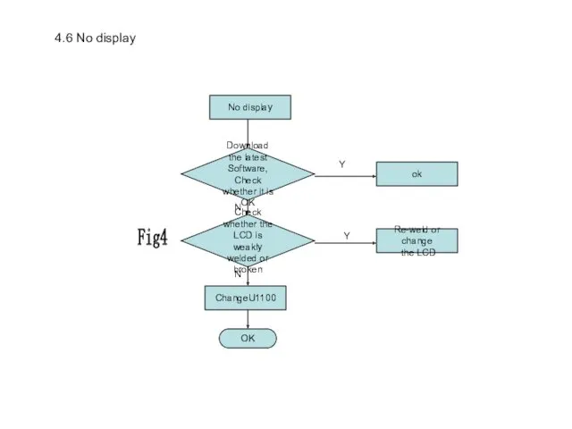
4.6 No display
No display
Download the latest Software,
Check whether it is OK
ok
N
Y
Check
4.6 No display
No display
Download the latest Software,
Check whether it is OK
ok
N
Y
Check
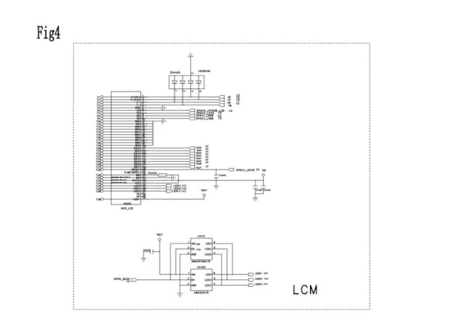
Fig4
Fig4
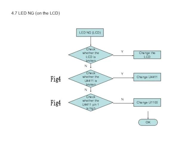
4.7 LED NG (on the LCD)
LED NG (LCD)
Check whether the
LCD is
4.7 LED NG (on the LCD)
LED NG (LCD)
Check whether the
LCD is
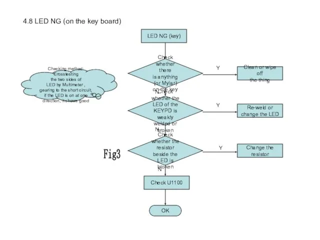
4.8 LED NG (on the key board)
LED NG (key)
Check whether the
LED
4.8 LED NG (on the key board)
LED NG (key)
Check whether the
LED
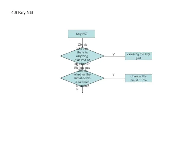
4.9 Key NG
Key NG
Check whether the
metal dome is oxidized
or broken
Change the
metal
4.9 Key NG
Key NG
Check whether the
metal dome is oxidized
or broken
Change the
metal
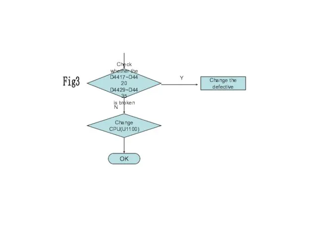
Check whether the
D4417~D4420 D4429~D4435
is broken
Change the defective
OK
Change CPU(U1100)
Fig3
N
Y
Check whether the
D4417~D4420 D4429~D4435
is broken
Change the defective
OK
Change CPU(U1100)
Fig3
N
Y
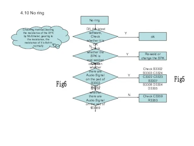
4.10 No ring
No ring
Check whether the
SPK is void-welded
or broken
Re-weld or
change the
4.10 No ring
No ring
Check whether the
SPK is void-welded
or broken
Re-weld or
change the
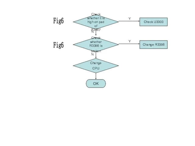
OK
Check whether it is high on pad of
R3357
Check U3300
Y
N
Check whether
R3356
OK
Check whether it is high on pad of
R3357
Check U3300
Y
N
Check whether
R3356
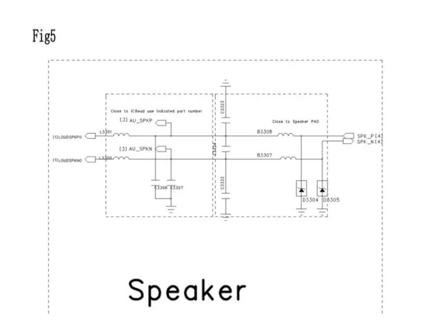
Fig5
Fig5
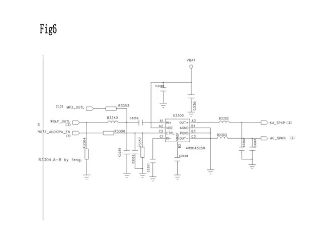
Fig6
Fig6
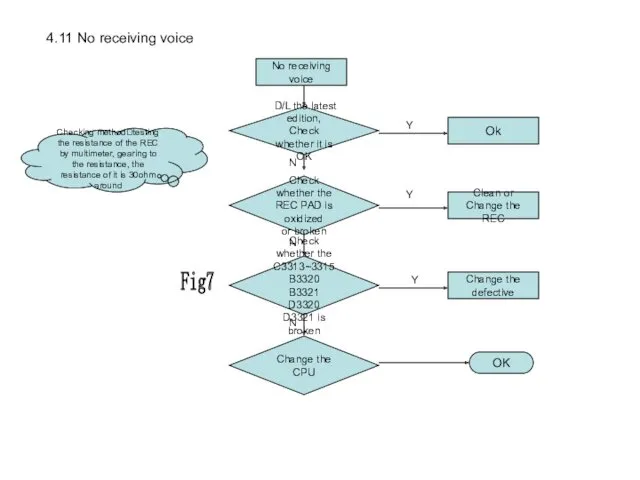
4.11 No receiving voice
No receiving voice
Check whether the
REC PAD is oxidized
or
4.11 No receiving voice
No receiving voice
Check whether the
REC PAD is oxidized
or
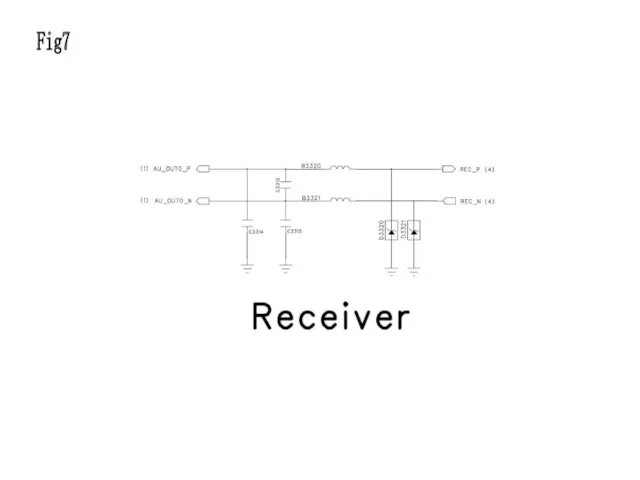
Fig7
Fig7
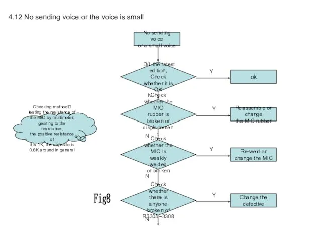
4.12 No sending voice or the voice is small
No sending voice
or
4.12 No sending voice or the voice is small
No sending voice
or
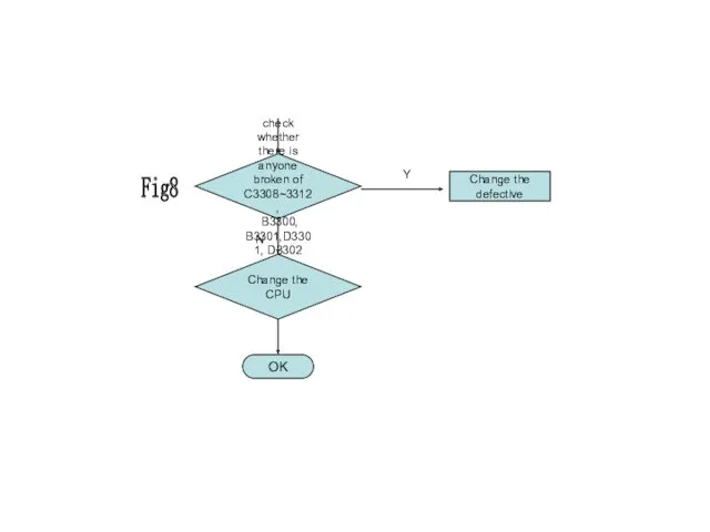
check whether there is
anyone broken of C3308~3312,
B3300, B3301,D3301, D3302
Change the
check whether there is
anyone broken of C3308~3312,
B3300, B3301,D3301, D3302
Change the
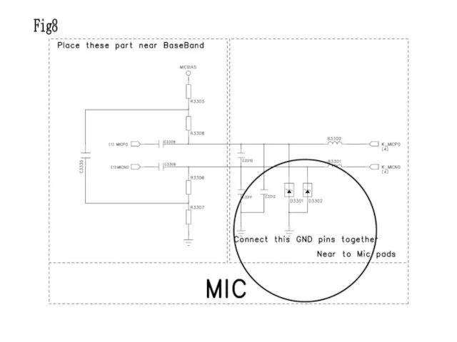
Fig8
Fig8
4.13 No vibration
No vibration
Check whether the
motor is locked by
displacement
Reassemble
the motor
Check whether
4.13 No vibration
No vibration
Check whether the
motor is locked by
displacement
Reassemble
the motor
Check whether
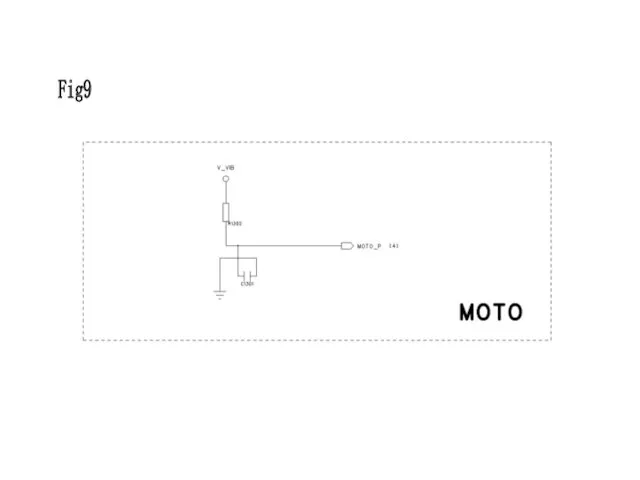
Fig9
Fig9
4.14 SIM Card inefficacy
SIM Card inefficacy
Check whether the SIM
card is broken
Change
4.14 SIM Card inefficacy
SIM Card inefficacy
Check whether the SIM
card is broken
Change
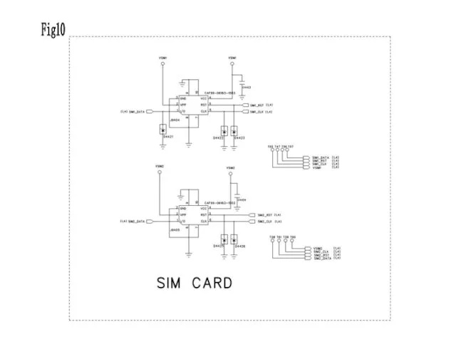
Fig10
Fig10
4.15 TF card inefficacy
TF NG
Check whether the
socket J9402 or J9403 is
4.15 TF card inefficacy
TF NG
Check whether the
socket J9402 or J9403 is
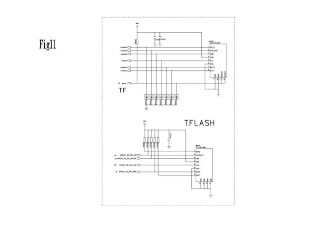
Fig11
Fig11
4.16 Camera inefficacy
Camera NG
Check whether the
camera is broken
Change the Camera
Check whether
4.16 Camera inefficacy
Camera NG
Check whether the
camera is broken
Change the Camera
Check whether
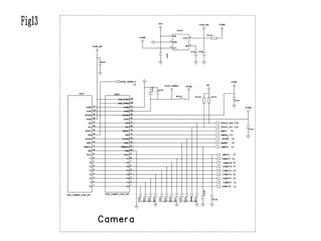
Fig13
Fig13
4.17 Bluetooth circuit(MT6612)
Bluetooth is a design feature of this cellphone. It
4.17 Bluetooth circuit(MT6612) Bluetooth is a design feature of this cellphone. It
4.17 Bluetooth inefficacy
BT NG
Check whether the
BT antenna is
touched well
Reassemble the
antenna
Check whether
C5307
4.17 Bluetooth inefficacy
BT NG
Check whether the
BT antenna is
touched well
Reassemble the
antenna
Check whether
C5307
Enable the BT function,
check whether C5302
has a voltage of 2.8V,
C5305 has
Enable the BT function,
check whether C5302
has a voltage of 2.8V,
C5305 has
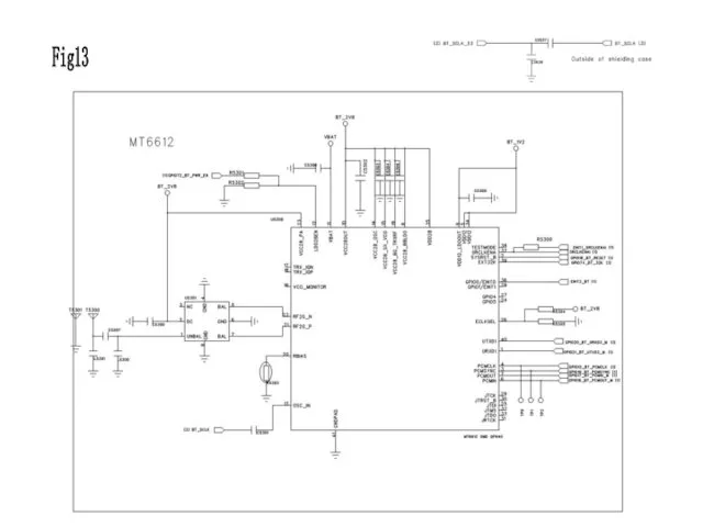
Fig13
Fig13
4.18 Earphone inefficacy
Earphone inefficacy
Check whether
the IO
connector ‘J9432’
is broken
Change J9432
Check whether the
earphone
4.18 Earphone inefficacy
Earphone inefficacy
Check whether
the IO
connector ‘J9432’
is broken
Change J9432
Check whether the
earphone
Check whether there is anyone
broken of C3300~C3304, R3301-
R3303, B3306, C3351, C3320
OK
Change
Check whether there is anyone
broken of C3300~C3304, R3301-
R3303, B3306, C3351, C3320
OK
Change
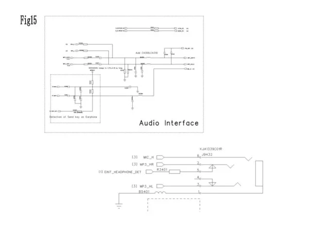
Fig15
Fig15
4.19 FM inefficacy
FM NG
Enable FM function,
check whether C4308
has a voltage
4.19 FM inefficacy
FM NG
Enable FM function,
check whether C4308
has a voltage
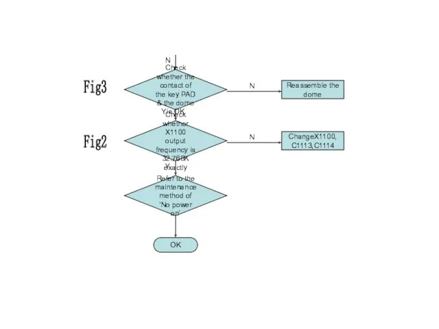
Check whether the
output frequency of
C4301 is 32.768K
Change C4301
OK
Change the
CPU
Change U4301
Change the
Check whether the
output frequency of
C4301 is 32.768K
Change C4301
OK
Change the
CPU
Change U4301
Change the
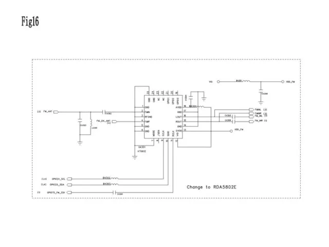
Fig16
Fig16
 ПРЕЗЕНТАЦИЯ: РАЗВИТИЕ ИГРОВОЙ ДЕЯТЕЛЬНОСТИ ДЕТЕЙ ДОШКОЛЬНОГО ВОЗРАСТА
 Строение периферического отдела скелета животных
 Описание климата по климатограммам
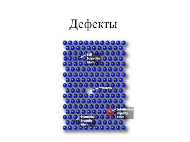 Кристаллизация Осмия. Дефекты. Поликристаллы
 Обструктивные уропатии
 Строение атома
 12 ИЮНЯ ДЕНЬ РОССИИ
 Предмет и метод экономической теории
 Урок естествознания 10 класс Традиции и революции в естествознании. Религиозная традиция
 Школы менеджмента
 Взаимодействие с родителями в процессе обучения ребёнка мелкой моторики.
 Классификация инноваций
 Минералы Урала
 презентация Реакции обмена
 Атмосфера. Ветер
 Презентация Фосфор
 Электропитание и электроснабжение нетяговых потребителей
 Презентация Трудности адаптации ребенка в 5 классе
 Северная война 1700-1721
 Разработка мобильных приложений на 1С и организация взаимодействия через Интернет
 Второстепенные члены предложения. Повторение и систематизация материала
 Развитию речи у детей старшего дошкольного возраста на тему: Здравствуй, лето!
 Кільватерне прискорення частинок в плазмі (plasma wakefield acceleration)
 Апаптоз патофизилогиясы
 Презентация Кабинет педагога-психолога
 Трипілля – Кукутені. Загадки унікальної культури
 Русская архитектура XVI - XVII веков
 Портфолио Натальи Рудяковой. Маркетолог